CNC PCB milling
-
Looks no worse than what I have .
-
I would like to create pcb's with a 0.5mm pitch as a target and I have tried to follow this thread for hints. Have you @andrew, @NeverDie or @executivul been able to get that done with the milling method?
Then one of the problems with the 2418 that @NeverDie seemed to have was that the machine itself was not stable enough. Do you think that the cheap 3018 work better? For example
https://www.aliexpress.com/store/product/CNC-3018-laser-options-with-ER11-diy-cnc-engraving-machine-Pcb-Milling-Machine-Wood-Carving-machine/424291_32806004900.html
or
https://www.amazon.com/Control-Machine-Engraver-Controller-Extension/dp/B07KYH6BTK/ref=sr_1_6?ie=UTF8&qid=1548751586&sr=8-6&keywords=cnc+3018 -
I would like to create pcb's with a 0.5mm pitch as a target and I have tried to follow this thread for hints. Have you @andrew, @NeverDie or @executivul been able to get that done with the milling method?
Then one of the problems with the 2418 that @NeverDie seemed to have was that the machine itself was not stable enough. Do you think that the cheap 3018 work better? For example
https://www.aliexpress.com/store/product/CNC-3018-laser-options-with-ER11-diy-cnc-engraving-machine-Pcb-Milling-Machine-Wood-Carving-machine/424291_32806004900.html
or
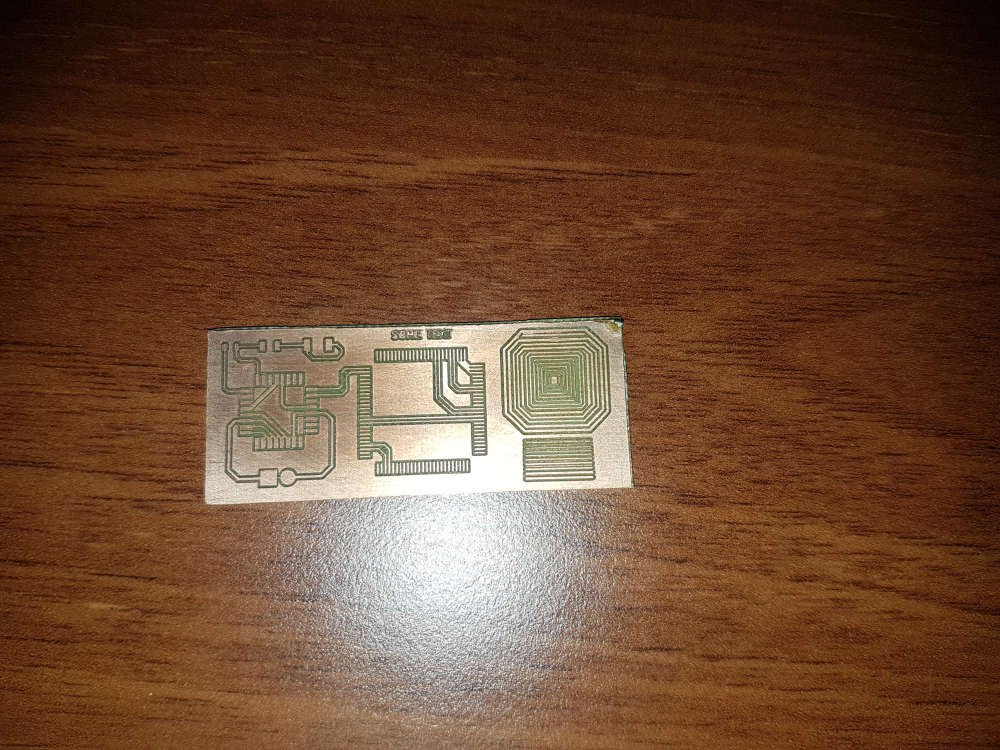
https://www.amazon.com/Control-Machine-Engraver-Controller-Extension/dp/B07KYH6BTK/ref=sr_1_6?ie=UTF8&qid=1548751586&sr=8-6&keywords=cnc+3018@lamikr pls see one of my very first test I made after I built my cnc. check the TQFP100 footprint.
for me, the cnc2418 was good choice. with proper assembly it is very stable and its output is stable.
I was using the cnc for designs down to 10mil traces without any issue.so, I have good experience with my low cost cnc but do to the lack of hands-on experience with other devices, I cannot compare or recommend others.
-
Hi everyone,
can someone help me pick out what to order from amazon.de?
I would like to order a 3018 pro, but which one?
What drilling bits would I need to order to mill PCB?
Any help much appreciated!!
@dennisc - I think its a matter of taste and preference, but there is 728 posts in this thread, many describing the pro and cons with different drillbits and mashines. Since its DIY its very hard to tell exactly what to pick - atleast for me - but lets see if someone else is bolder.
-
@dennisc - I think its a matter of taste and preference, but there is 728 posts in this thread, many describing the pro and cons with different drillbits and mashines. Since its DIY its very hard to tell exactly what to pick - atleast for me - but lets see if someone else is bolder.
I know there are so many posts!
I am under a bit of time pressure and can't wait for aliexpress or bang good, so I was hoping somebody just ordered something off amazon. (and I could copy that).
I am interested in the 3018 Pro, that on looks good enough price wise at least. But maybe had an experience with Sainsmart or something else.
Other important reason is that there have not been many posts in the last months in this thread.
-
Ok calibration was quite easy.
I managed to get the x, y and z axis zeroed. Only thing I am wondering is this:
I can see my file goes 0.2 mm deep. Is there a button to alter the offset?
I found I had to do all kind of fake zeroing to get it deeper!
-
Ok calibration was quite easy.
I managed to get the x, y and z axis zeroed. Only thing I am wondering is this:
I can see my file goes 0.2 mm deep. Is there a button to alter the offset?
I found I had to do all kind of fake zeroing to get it deeper!
@dennisc I have myself ordered the 2418 from the Jack's store.
I also ordered the parts for Ant's team's PCB machine based on the BOM on
https://bitbucket.org/compactpcbmaker/cpcbm/src/masterIt will be intersted in for comparing these two and I think money will not be wasted as other one could in the end anyway be used for drilling if other one does the route milling.
Another thing I am wondering how this will compare to Eleksmaker A3 with 405nm laser and Marco Reps modifications.
https://www.youtube.com/watch?v=ZzO9skEYqwYLaser is interesting due to it's accuracy but I am worried from the reflected beams. I have only found out so classes for protecting from the beam but would rather like to see a full box made from proper shielding material on top of the Eleksmaker.
Fourths interesting thing is the openpnp based pasta dispenser and pick and place machine.
https://hackaday.io/project/165743-foxbuild-pnp
https://mcuoneclipse.com/2018/06/26/building-a-diy-smt-pickplace-machine-with-openpnp/ -
@dennisc I have myself ordered the 2418 from the Jack's store.
I also ordered the parts for Ant's team's PCB machine based on the BOM on
https://bitbucket.org/compactpcbmaker/cpcbm/src/masterIt will be intersted in for comparing these two and I think money will not be wasted as other one could in the end anyway be used for drilling if other one does the route milling.
Another thing I am wondering how this will compare to Eleksmaker A3 with 405nm laser and Marco Reps modifications.
https://www.youtube.com/watch?v=ZzO9skEYqwYLaser is interesting due to it's accuracy but I am worried from the reflected beams. I have only found out so classes for protecting from the beam but would rather like to see a full box made from proper shielding material on top of the Eleksmaker.
Fourths interesting thing is the openpnp based pasta dispenser and pick and place machine.
https://hackaday.io/project/165743-foxbuild-pnp
https://mcuoneclipse.com/2018/06/26/building-a-diy-smt-pickplace-machine-with-openpnp/@lamikr said in CNC PCB milling:
Laser is interesting due to it's accuracy but I am worried from the reflected beams. I have only found out so classes for protecting from the beam but would rather like to see a full box made from proper shielding material on top of the Eleksmaker.
Fourths interesting thing is the openpnp based pasta dispenser and pick and place machine.
https://hackaday.io/project/165743-foxbuild-pnp
https://mcuoneclipse.com/2018/06/26/building-a-diy-smt-pickplace-machine-with-openpnp/I made an enclosure for my 3D printer in which I had a plexiglass panel for the door. Not long ago I made a mod for my 3D printer that allows me to change to different tool heads. https://www.thingiverse.com/thing:3407486
One of the tools is a 6 watt laser module. I got a piece of this to replace the plexiglass on the door of my enclosure. It is rated for the wavelength of my laser module which is 450nm. https://jtechphotonics.com/?product=445nm-laser-shielding This might be a bit small if you wanted to make a complete cover made out of this stuff though.
-
@lamikr said in CNC PCB milling:
Laser is interesting due to it's accuracy but I am worried from the reflected beams. I have only found out so classes for protecting from the beam but would rather like to see a full box made from proper shielding material on top of the Eleksmaker.
Fourths interesting thing is the openpnp based pasta dispenser and pick and place machine.
https://hackaday.io/project/165743-foxbuild-pnp
https://mcuoneclipse.com/2018/06/26/building-a-diy-smt-pickplace-machine-with-openpnp/I made an enclosure for my 3D printer in which I had a plexiglass panel for the door. Not long ago I made a mod for my 3D printer that allows me to change to different tool heads. https://www.thingiverse.com/thing:3407486
One of the tools is a 6 watt laser module. I got a piece of this to replace the plexiglass on the door of my enclosure. It is rated for the wavelength of my laser module which is 450nm. https://jtechphotonics.com/?product=445nm-laser-shielding This might be a bit small if you wanted to make a complete cover made out of this stuff though.
@dbemowsk Thanks for the shielding material tip, I may buy it later if starting to work with 0.5w 405nm laser for engraving. (Some safe enclosure definetly needed)
In the meantime I have not constructed my CNC 2418 from Jack's store and tested that I can control it by seding the g-gode commands from terminal. I have not yet tried to workflow from Kicad, to flatcam and from there to bCNC.
Original GRBL firmware was 0.9j but I managed to upgrade it to v1.1h over USP without need for using another arduino as a ISP programmer and wiring it to woodpecker. Arduino-ide did not detect the board automatically but the flashing to grbl 1.1h worked with a following command out of the box on my linux by using a following avrdude command:
avrdude -v -C/etc/avrdude/avrdude.conf -pm328p -carduino -P /dev/ttyUSB0 -D -Uflash:w:grbl_v1.1h.20190825.hexThis thread is so long that it takes lot of time to try to find all important steps. But what I have gathered is that 3 most important things that I am still missing before trying to mill are the
-
auto leveling
What I read, this should be easy with gBNC. Mostly connect one wire from the drilling bit to A5 pin in woodpecker and another from woodpecker's ground to pcb. -
Current adjustment for all three A4988 motors.
If I understood correctly @andrew and @NeverDie both changed that from 0.6A to 0.9A? Can that be done only by rotating the potentiometer on a4988 driver boards or do I also need to add some resistors? -
End stops modules? Could them be connected somehow to woodpecker?
-
-
Looks like the price on more precise equipment has come down:
https://www.aliexpress.com/item/32889386703.html?spm=a2g0o.detail.1000014.25.50f15e323iLiE4&gps-id=pcDetailBottomMoreOtherSeller&scm=1007.13338.141931.0&scm_id=1007.13338.141931.0&scm-url=1007.13338.141931.0&pvid=6d201006-5b15-41db-bc2e-2f9421010139Either this or a more classic mill setup is probably the most cost effective for cutting pcbs more accurately. It's the twisting slop that most limits my current CNC's PCB fidelity.
-
On my previous attempts, I wasn't aware there existed any options for milling PCB's beyond just v-bits. Now it seems that there's quite a range of actual end-mill bits in diameters as narrow as 0.05mm!
They look like this:

From what I've read, when using end mills with less than 100 micron cutting diameters, it's recommended to do step cutting, due to the delicate nature of the bit. That's fine with me: once I set up the machine with a PCB blank, I can walk away and come back when it's done.
Anyone tried using end mill bits like these for milling PCB's, and if so, how do they compare?
-
Looks like the price on more precise equipment has come down:
https://www.aliexpress.com/item/32889386703.html?spm=a2g0o.detail.1000014.25.50f15e323iLiE4&gps-id=pcDetailBottomMoreOtherSeller&scm=1007.13338.141931.0&scm_id=1007.13338.141931.0&scm-url=1007.13338.141931.0&pvid=6d201006-5b15-41db-bc2e-2f9421010139Either this or a more classic mill setup is probably the most cost effective for cutting pcbs more accurately. It's the twisting slop that most limits my current CNC's PCB fidelity.
@NeverDie I've got this one several months ago, I couldn't say it's a good one though.
here is the list of drawbacks I've had/have:- spindle fixed speed 12000RPM. I added automatic circuit breaker to it so it won't put home on fire when it rams into the table. (threw away DC connector on top as it wasn't reliably holding both sides to begin with and then it was burned a bit after spindle stall). Runout is about 50um. + whatever collet would add (cheapest ones from aliexpress were disappointment in a range 50~100um, so I've got precision one locally)
The only thing I'm going to invest into this machine is 24K spindle + vfd with small runout. (it just arrived but still unpacked, it will need adapter plate to mount it on Z plate, hopefully I'll make something with adjustable tilt to simplify tramming) - it was poor assembled, one has to disassemble and put it back properly tightening screws and making sure belts are not loose (that solved lost steps issue)
- it uses lead screws with bronze nuts like in 3D printers and a plastic spacer between nuts (to counter backlash).
- axis plates are attached to nuts via that same plastic spacer (not sure how it would do with milling aluminium)
- there was (still is) some backlash (~40-60um) left after tightening nuts,
one could tighten it further but that would come at cost of lower speeds as no-name steppers start stalling (currently I have 2300mm/min max on XY plane, and one would wish for more rapids if one would wish to try milling plastics) - squaring it is nightmare, basically the only option you have is adjusting X pillars and try to square XY and YZ at the same time (and there isn't much space to play with it). For tramming spindle on XZ plane, I had to move up one side of X support plate as there isn't sufficient play in spindle mount and then level sacrificial board to make X axis square to the table.
As result of several iterations, I've got ±40um difference in hight across the table. XY axises still not square ~0.5mm on opposite sides of of the table on X axis, but I don't have heart to repeat whole procedure again (yet). - controller dial is way too sensitive, so I practically don't use it at all. Ribbon cable to SD card fell appart, USB connector for PC doesn't work reliably (but mostly works if you got it in working position).
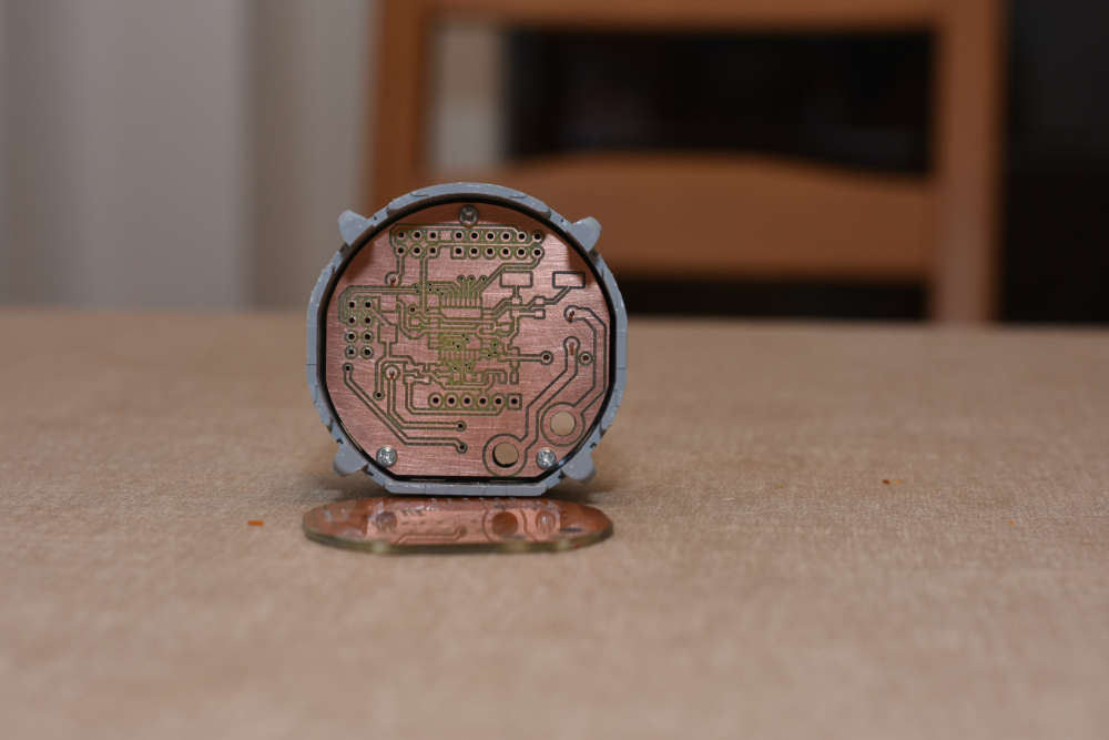
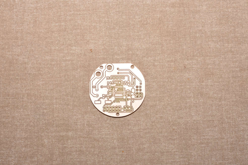
The whole setup was bought to prototype PCBs and later on learn how to mill other stuff (plastics/aluminium) for casing prototypes.
So far I've managed to mill reliably 0.3mm isolation paths with 60*0.2 engraving bit (but as you did, I've redesigned board with wider traces to reduce failure chances). In Flatcam, I had to add runout value to tip diameter to avoid track thinning. Perhaps I could do more fine traces now (after all the tuning) with more fragile 30 or 15 degree bits, but I won't try till I get current project out of the door (at least hardware part of it).
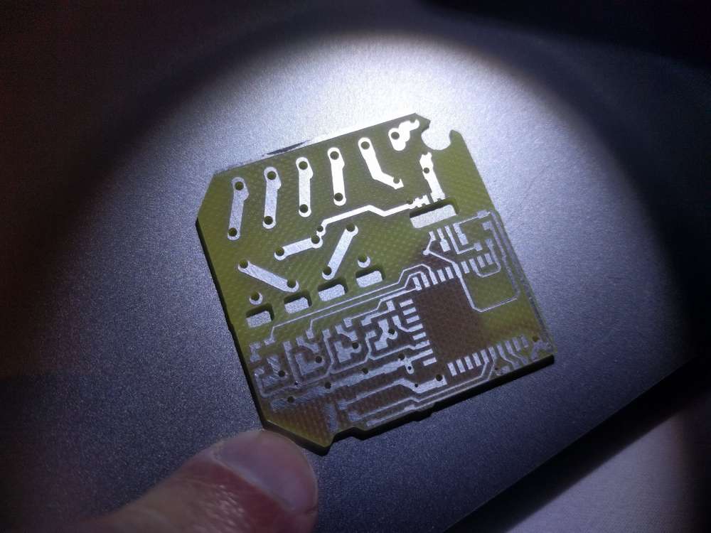
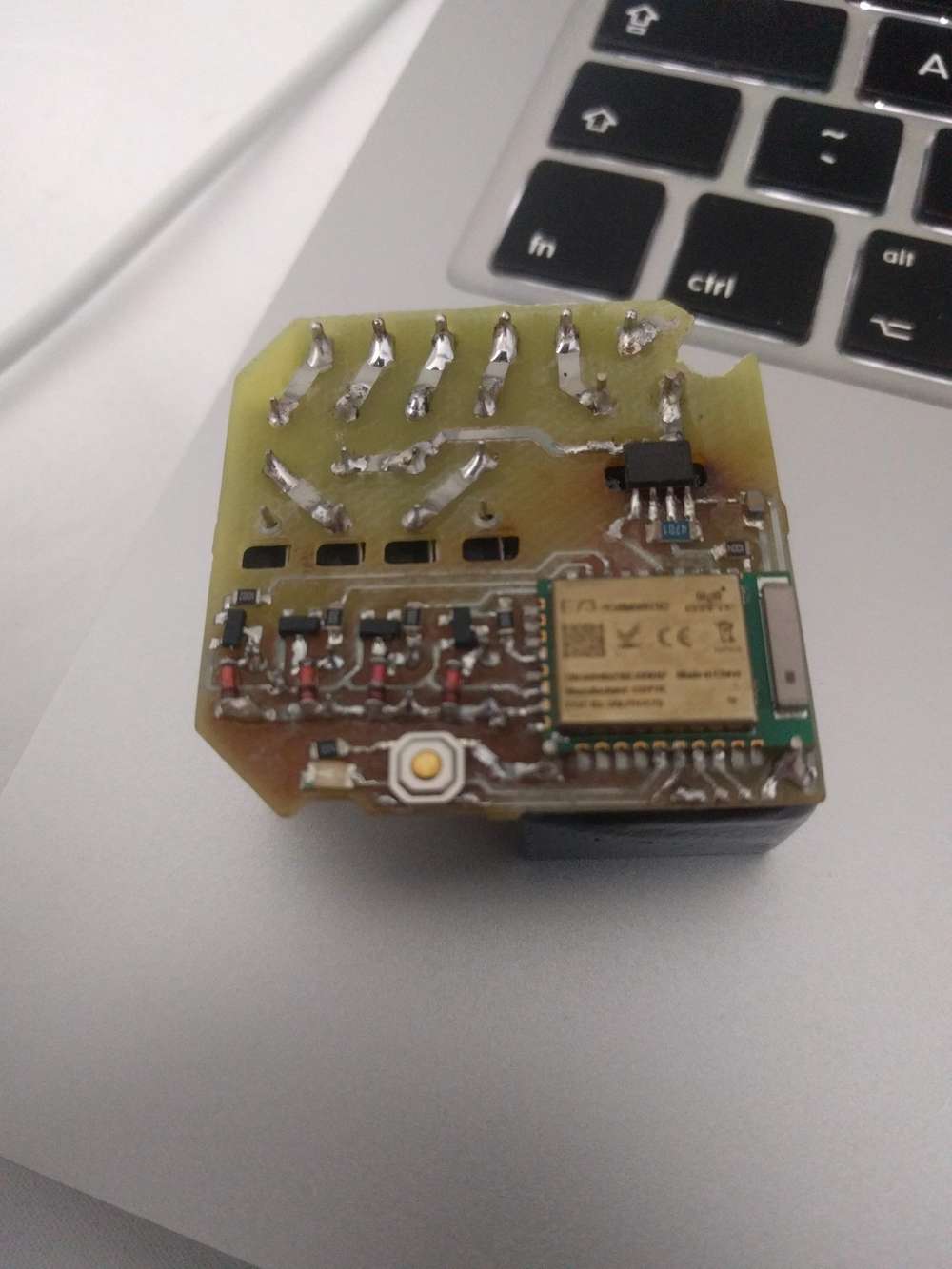
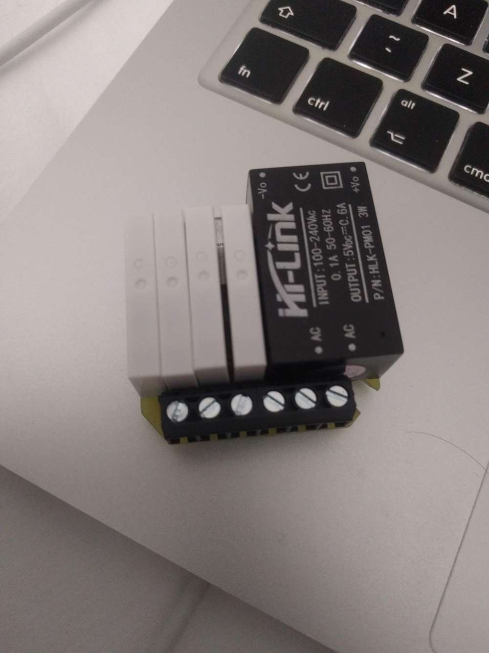
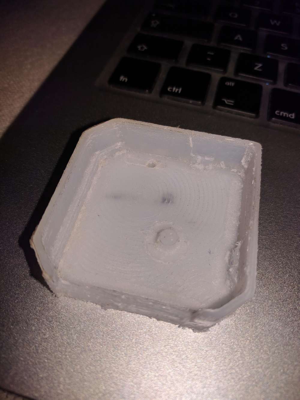
and here is my 1st attempt to mill the case part
- spindle fixed speed 12000RPM. I added automatic circuit breaker to it so it won't put home on fire when it rams into the table. (threw away DC connector on top as it wasn't reliably holding both sides to begin with and then it was burned a bit after spindle stall). Runout is about 50um. + whatever collet would add (cheapest ones from aliexpress were disappointment in a range 50~100um, so I've got precision one locally)
-
I received one of the 0.2mm end mill bits, so I'll be having a run at it with that sometime soon. To give it the best chance, I plan to bed level with some large diameter endmills first, as I haven't tried that before and maybe it will help. Looking forward to it.
Wegster has a series of impressive videos on youtube that are an inspiration that this is actually possible to do with fairly ordinary looking equipment (though they charge a small fortune for theirs):
https://www.youtube.com/watch?v=cCm-UL-dCEcMaybe there's more to it than meets the eye? Makes me wonder what exactly they're doing in order to accomplish it so perfectly.
An alternative might be to connect a sharpie type pen and plot that way as a prelude to chemical etching. I haven't wanted to do that, but it's a fallback that might work to get fine pitch etches.
Hackaday did a very insightful analysis of "the mother mill" which explained why it is surprisingly good at milling PCBs despite it's having a largely plastic frame construction:
https://hackaday.com/2016/08/02/the-othermill-vs-import-a-technical-comparison/
Usually success begets knock-offs, but I can't say that I've noticed any knockoffs of the OtherMill.I'd really like to have a machine with an automatic tool changer, where I could just launch it and come back when it's totally done with everything. I'm surprised that capability hasn't yet become more widespread.
-
Anyone else out there using CNC to make their own PCB's? After taking a break from it for a while, I'm going to take another stab at it, now with the benefit of fresh eyes. Right off the bat I'm making a few changes:
- Flattening a space for the PCB on the sacrificial board so that little to no bed leveling will be required:
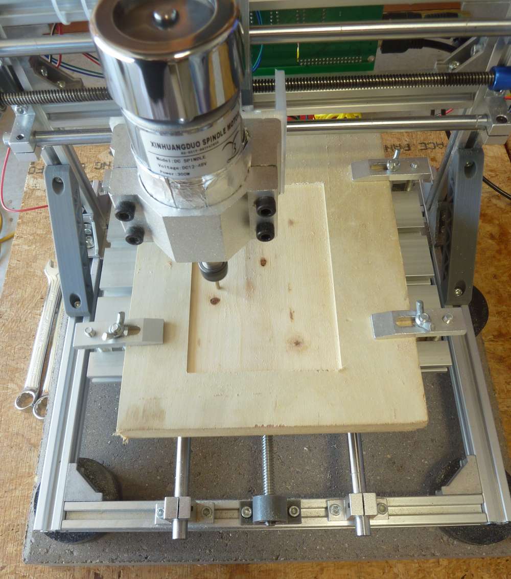
- As seen in the photo just above, using a concrete paver to stabilize the platform. This is a common tactic used in 3D printers.
- Mounting the printer on non-skid pucks (also shown in the photo) to guarantee that the CNC doesn't slide around.
- Using FR-1 instead of FR-4 as the substrate for the copper clad PCB.
- As already mentioned in the post just above, using end-mill bits instead of v-bits to accomplish the etching.
- Oh, and yes, I replaced the spindle I was previously using with this upgraded, more powerful spindle.
- Using a stronger double-sided tape ("Nitto Tape") to hold the PCB in position while the PCB is being etched by the CNC. Actually, I'm not unsure as to whether it's stronger than the double sided golf grip tape I was using previously, but I'm trying it today, so I'll soon have a basis on which to gauge it.
- Laying around somewhere I have some TMC drivers, and when I find them I'll use them to upgrade the rudimentary GRBL controller that came with the original CNC kit. Not sure if it will yield any improvements, but, meh, seems like it's worth trying.
- I've switched to a domestic fabricator of blank PCBs that I'll use instead of the Aliexpress ones. I don't know whether it will make a difference, but the quality does seem to be higher, and I can get them with thicker substrates than what I can find on aliexpress.
- I switched to a metal spindle mount.
I've already noticed one anomaly that I hadn't noticed previously, which is that if I use Flatcam to set the depth of cut to 1.5875mm (equals 1/16 of an inch), then if I do it in 4 passes (where the first pass is at 0.5mm depth, the second at 1.0mm depth, the third at 1.5mm depth, and finally the last pass at 1.5875mm, I end up getting a shallower depth of cut than if I were to later do a depth of cut of 1.5875mm in just one pass. Not sure if this is caused by an error in chillipepr, the gerbal controller, or the stepper missing steps.
Meanwhile, software seems to have improved since the last time I was using it, so I'm looking forward to trying it again as well as new alternatives. Anyone here have any favorites?
- Flattening a space for the PCB on the sacrificial board so that little to no bed leveling will be required:
-
I wasn't getting a completely smooth flattened area using just a 1/8" end mill, so I'm going to hazard a try with https://www.amazon.com/gp/product/B0000225VS/ref=ppx_yo_dt_b_asin_title_o00_s00?ie=UTF8&psc=1
by switching to a 1/4" collet in my ER11 spindle. -
SOLVED: up until now I was running the "stable" release of FlatCAM, but it turned out to be so full of shortcomings that I decided to throw caution to the wind and install the latest beta release instead. I'm glad I did. Not only did it fix a range of problems that the stable release had, but it also has a "finishing" setting that's doing a much better job of smoothing out my spoilboard using a mere garden variety 1/8" end mill. :-) The main downside is that the "finishing" algorithm can take quite a while to run, so for speed's sake I'll still give the Freund a try. Freund cutting tools are pretty good quality, so I expect it will be an improvement.
-
@NeverDie I've got this one several months ago, I couldn't say it's a good one though.
here is the list of drawbacks I've had/have:- spindle fixed speed 12000RPM. I added automatic circuit breaker to it so it won't put home on fire when it rams into the table. (threw away DC connector on top as it wasn't reliably holding both sides to begin with and then it was burned a bit after spindle stall). Runout is about 50um. + whatever collet would add (cheapest ones from aliexpress were disappointment in a range 50~100um, so I've got precision one locally)
The only thing I'm going to invest into this machine is 24K spindle + vfd with small runout. (it just arrived but still unpacked, it will need adapter plate to mount it on Z plate, hopefully I'll make something with adjustable tilt to simplify tramming) - it was poor assembled, one has to disassemble and put it back properly tightening screws and making sure belts are not loose (that solved lost steps issue)
- it uses lead screws with bronze nuts like in 3D printers and a plastic spacer between nuts (to counter backlash).
- axis plates are attached to nuts via that same plastic spacer (not sure how it would do with milling aluminium)
- there was (still is) some backlash (~40-60um) left after tightening nuts,
one could tighten it further but that would come at cost of lower speeds as no-name steppers start stalling (currently I have 2300mm/min max on XY plane, and one would wish for more rapids if one would wish to try milling plastics) - squaring it is nightmare, basically the only option you have is adjusting X pillars and try to square XY and YZ at the same time (and there isn't much space to play with it). For tramming spindle on XZ plane, I had to move up one side of X support plate as there isn't sufficient play in spindle mount and then level sacrificial board to make X axis square to the table.
As result of several iterations, I've got ±40um difference in hight across the table. XY axises still not square ~0.5mm on opposite sides of of the table on X axis, but I don't have heart to repeat whole procedure again (yet). - controller dial is way too sensitive, so I practically don't use it at all. Ribbon cable to SD card fell appart, USB connector for PC doesn't work reliably (but mostly works if you got it in working position).
The whole setup was bought to prototype PCBs and later on learn how to mill other stuff (plastics/aluminium) for casing prototypes.
So far I've managed to mill reliably 0.3mm isolation paths with 60*0.2 engraving bit (but as you did, I've redesigned board with wider traces to reduce failure chances). In Flatcam, I had to add runout value to tip diameter to avoid track thinning. Perhaps I could do more fine traces now (after all the tuning) with more fragile 30 or 15 degree bits, but I won't try till I get current project out of the door (at least hardware part of it).
and here is my 1st attempt to mill the case part
@niallain As far as v-bits go, I've lately had good results with this type:
https://www.amazon.com/gp/product/B019K4OMBE/ref=ppx_yo_dt_b_search_asin_title?ie=UTF8&psc=1It's not as fragile as the typical aliexpress style v-bits.
- spindle fixed speed 12000RPM. I added automatic circuit breaker to it so it won't put home on fire when it rams into the table. (threw away DC connector on top as it wasn't reliably holding both sides to begin with and then it was burned a bit after spindle stall). Runout is about 50um. + whatever collet would add (cheapest ones from aliexpress were disappointment in a range 50~100um, so I've got precision one locally)
-
It's now possible to use an inexpensive open source controller to achieve both closed loop control and 0.02 degree resolution on a nema 17 stepper: https://hackaday.io/project/11224-mechaduino
I get the impression the original maker isn't selling it anymore. So, you can make it yourself from the files posted or github, or a number of inexpensive clones are also available on aliexpress for around $15. By use of a magnetic encoder, it basically immediately corrects for any missed steps. In the case of 3D printing, that means no layer shifts, even if, as demonstrated in this youtube video, you were to whack the printhead hard with a rubber mallet during a print:
As for CNC, it's a new level of control assuredness.
Also, because the drivers offer a way to directly monitor how hard the servos are working, they should provide a way to make better informed decisions about increasing speed, acceleration, etc.
UStepper appears to be another board that was conceived along similar lines.
I'm planning to upgrade my nema 17's to ones with 3x the torque, and then later upgrade those upgrades with mechaduino/ustepper closed loop controllers. By sticking with nema 17, all these should be drop-in replacements for what's already there. i.e. no need to change couplers or other fittings.
For even greater torque and precision I could outfit the steppers with planetary gearboxes, but, meh, I'll evaluate that after the upgrades already pending are completed. I presume they come with a downside of much slower speed.
Anyone here done any of this? How did it go?