CNC PCB milling
-
@executivul Do you put down something over the paint (such as plastic, for instance) before rolling over it, or do you roll directly over the wet paint with the roller itself?
@NeverDie I put a piece of clear "document wrap foil"

-
It makes sense. AFAIK, the uv solder mask paint isn't benefited from the laminator heat, just the uniform squeezing from the rollers.
-
The stack goes like this:
-glass
-normal printer paper made transparent to UV light (https://www.amazon.co.uk/Kontakt-chemie-Transparent-21-Spray-200ml/dp/B00ID6KY4K)
-toner (the image is mirrored and placed toner face down)
-transparent film from "document wraps"
-UV solder mask paint
-pcb
-glassThe top and bottom glass pieces are held tight by some binder clips.
-
That's an interesting spray. I'll have to do some hunting to see if I can find a US distributor for that.
-
That's an interesting spray. I'll have to do some hunting to see if I can find a US distributor for that.
-
@NeverDie or just try some canola oil spilled on normal laser printer paper ;)
@executivul
Is it better to use that spray with regular printer paper than just printing to a transparency? -
@executivul
Is it better to use that spray with regular printer paper than just printing to a transparency?@NeverDie My printer has a problem with transparencies (jams) and also the high cost for transparencies made me go the paper route, if the toner is facing down the distance is the same as when using transparency printed artwork, also the paper "softens" the uv led light and makes it more uniform I guess.
-
@NeverDie My printer has a problem with transparencies (jams) and also the high cost for transparencies made me go the paper route, if the toner is facing down the distance is the same as when using transparency printed artwork, also the paper "softens" the uv led light and makes it more uniform I guess.
I use the same kind of plastic folder. They are dirt cheap. And yesterday I used the same one twice.
@NeverDie it was late in the night already. I meant 2 mils :-).
Yes the laminator is only rolling, there is no heat involved.
-
Note sure if it's overkill or actually a good idea, but it looks as though so-called "cold" laminators exist, where you can adjust the pressure:
https://www.amazon.com/dp/B07Z4VSTZC/ref=sspa_dk_detail_1?psc=1&spLa=ZW5jcnlwdGVkUXVhbGlmaWVyPUEzUTk5WjRINjJVWTRDJmVuY3J5cHRlZElkPUEwNDE5MTk5MUpSUE1QTzQ3UEkzRyZlbmNyeXB0ZWRBZElkPUEwMzk5OTIxMjY5NUkyQkI2SFVLQyZ3aWRnZXROYW1lPXNwX2RldGFpbDImYWN0aW9uPWNsaWNrUmVkaXJlY3QmZG9Ob3RMb2dDbGljaz10cnVl
You could dial in a uniform pressure. -
Note sure if it's overkill or actually a good idea, but it looks as though so-called "cold" laminators exist, where you can adjust the pressure:
https://www.amazon.com/dp/B07Z4VSTZC/ref=sspa_dk_detail_1?psc=1&spLa=ZW5jcnlwdGVkUXVhbGlmaWVyPUEzUTk5WjRINjJVWTRDJmVuY3J5cHRlZElkPUEwNDE5MTk5MUpSUE1QTzQ3UEkzRyZlbmNyeXB0ZWRBZElkPUEwMzk5OTIxMjY5NUkyQkI2SFVLQyZ3aWRnZXROYW1lPXNwX2RldGFpbDImYWN0aW9uPWNsaWNrUmVkaXJlY3QmZG9Ob3RMb2dDbGljaz10cnVl
You could dial in a uniform pressure.@NeverDie for $99.99 I would roll the s#it out of it with my hand roll, heck I would even step on it with my pressure controlled 200 lbs weight in pink slippers.
-
Note sure if it's overkill or actually a good idea, but it looks as though so-called "cold" laminators exist, where you can adjust the pressure:
https://www.amazon.com/dp/B07Z4VSTZC/ref=sspa_dk_detail_1?psc=1&spLa=ZW5jcnlwdGVkUXVhbGlmaWVyPUEzUTk5WjRINjJVWTRDJmVuY3J5cHRlZElkPUEwNDE5MTk5MUpSUE1QTzQ3UEkzRyZlbmNyeXB0ZWRBZElkPUEwMzk5OTIxMjY5NUkyQkI2SFVLQyZ3aWRnZXROYW1lPXNwX2RldGFpbDImYWN0aW9uPWNsaWNrUmVkaXJlY3QmZG9Ob3RMb2dDbGljaz10cnVl
You could dial in a uniform pressure.@NeverDie you might as well buy those specialized springloaded engraving bits from Wegstr. If you are willing to invest this money.
These hot/cold laminators cost 15 euro here.
-
I'll try it both ways. I've already own roughly the same kind of roller as executivul, so I'll try that first. My wife has a laminator that takes 20 minutes to warm up, so I could pass it through that before it gets hot.
I was leaning toward the screed approach, but not sure if would still work well if there's going to be artwork placed on top. Meh, maybe just flatten it in a press. That would do it for sure (well, if the plates are parallel that is).
@NeverDie oh btw, I have not seen air bubbles.
-
I just now stumbled across this, which is actually kinda interesting:
How To Make Your Own Screens For Screen Printing – 03:36
— The Craft StoreBasically it shows that with very little time or effort you can create a print screen. If you were to create a print screen for solder mask, you could squeegee the solder mask through the print screen onto the PCB and the solder mask paint would be printed just exactly where you wanted it to be and nowhere else. Then all you would have to do is UV cure it, and you'd be done.
To illustrate, here's a video of what looks like wretchedly impoverished people making PCB's, but it illustrates print screening of solder mask:
Best pcb green masking from screen printing process by DSP Enterprises – 01:34
— Deepak Kumar(Prior to this scene, the same poor souls used the same screen print method to lay down the copper mask. They then etched the copper, which led directly to this scene). The quality seems consistent with a lot of the cheap boards one might come across on aliexpress.
It also opens the door to the possibility of having real "silk screen" printing of artwork onto the final PCB as well. which so far I haven't seen any other discussion regarding how to do.
In terms of cost, it's more expensive than the techniques we've so far been discussing, but the cosumables are less costly than, say, sending off to JLPCB with rapid DHL return shipping, and you obviously get the results far faster than JLPCB would ever be able to deliver them to your doorstep. Plus, for small PCB's it seems likely that you could cut down the fabric to only the amount needed, and thus the material costs could be stretched out over possibly many different design iterations.
-
"Houston, we have closed the loop."
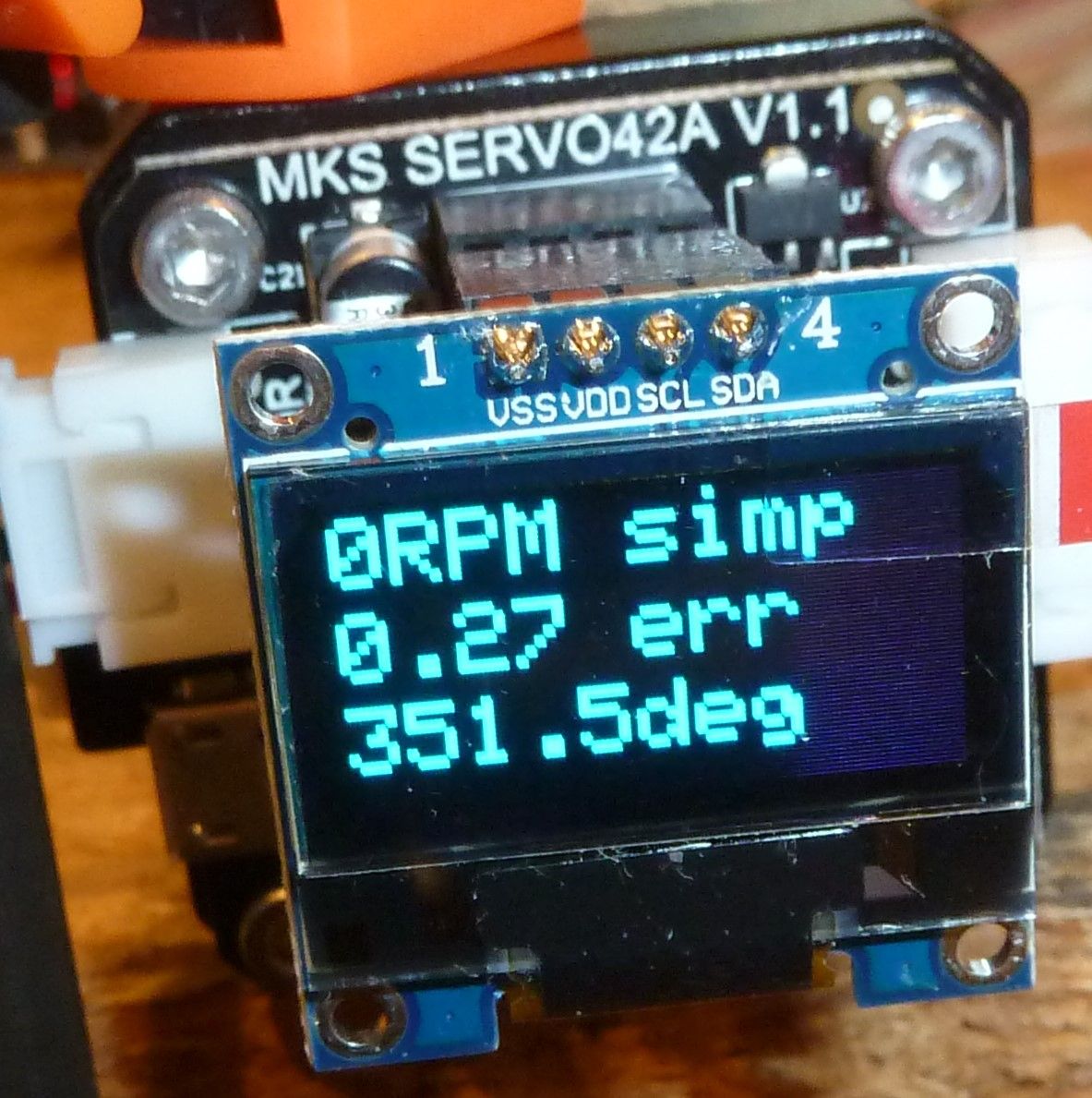
It's up and running. In 256 step mode, it is barely even audible.
However, given that, for a closed loop system the picture seems to represent a anomaly. Can you guess what it is? After jogging the motor around a bit, I stopped and let the stepper idle at what it thinks should be 351.5deg, based on the steps that I sent to it, but which the encoder measures as being 0.27 degree different than that. Well, we know that a full step would be 1.8 degrees, so if it is truly microstepping at 256 ,that means that each microstep should be able to advance the motor by 1.8/256=0.007 degree. Right? So, here's the rub: if the motor is idling, why hasn't it corrected, or at least significantly reduced, the 0.27 degree error? 0.007 degree is much less than 0.27 degree, so it should have adjusted the stepper's true position to be much closer to what its theoretical position should be. Yet, it isn't. Why not?
Well, maybe it can't actually do 256 microsteps. Maybe it can do only 128. That would mean that it should be able to make each microstep be 0.14 degree. Right? But, if that were true, then being closed loop it again should have moved the stepper to bring it closer to what it should be. But it didn't.
So, here's my theory: it's can't actually do 128 microsteps either. Maybe the most it can do is 64 microsteps. In that case, each microstep would be 0.28 degree. Right? But the error is 0.27 degree, which is less than 0.28 degree. Maybe that's where their algorithm gives up and stops. However, if it were me writing the code, I would have made it so that it moves one microstep closer to where it should be, even if that means overshooting by 0.01 degree. That's because being off by 0.01 degree is better than being off by 0.27 degree. But it didn't do that.
However, if we assume that whoever wrote the code actually did the best job that could be done at closing the loop in this scenario, then the obvious conclusion is that this stepper driver can actually do at most 32 microstepping and nothing more. Why? Because in that case each microstep would be 0.56 degree, and so trying to close the loop by moving the stepper one microstep toward the position it ideally should have would mean overshooting by an amount greater than 0.27 degree, and so it's actually better to do nothing in this particular situation.
But if that's the case, why advertise it to have more microstepping than what it's actually capable of?
Anyhow, that's as far as I've gotten with it so far. I guess the next step will be to open up a terminal window to view its output over the usb connection. Perhaps that will shed more light on the mystery.
Edit: Whooops. 1.8 degree divided by 32 is 0.056, not 0.56, so my calculations above are off. Well, I'm heading off to bed right now, so I'll look into that discrepancy tomorrow. Meanwhile, if anyone has thoughts on the 0.27 degree anomaly, feel free to post.
That's it for today. Signing off. :sleeping: :sleeping_accommodation:
-
I just now stumbled across this, which is actually kinda interesting:
How To Make Your Own Screens For Screen Printing – 03:36
— The Craft StoreBasically it shows that with very little time or effort you can create a print screen. If you were to create a print screen for solder mask, you could squeegee the solder mask through the print screen onto the PCB and the solder mask paint would be printed just exactly where you wanted it to be and nowhere else. Then all you would have to do is UV cure it, and you'd be done.
To illustrate, here's a video of what looks like wretchedly impoverished people making PCB's, but it illustrates print screening of solder mask:
Best pcb green masking from screen printing process by DSP Enterprises – 01:34
— Deepak Kumar(Prior to this scene, the same poor souls used the same screen print method to lay down the copper mask. They then etched the copper, which led directly to this scene). The quality seems consistent with a lot of the cheap boards one might come across on aliexpress.
It also opens the door to the possibility of having real "silk screen" printing of artwork onto the final PCB as well. which so far I haven't seen any other discussion regarding how to do.
In terms of cost, it's more expensive than the techniques we've so far been discussing, but the cosumables are less costly than, say, sending off to JLPCB with rapid DHL return shipping, and you obviously get the results far faster than JLPCB would ever be able to deliver them to your doorstep. Plus, for small PCB's it seems likely that you could cut down the fabric to only the amount needed, and thus the material costs could be stretched out over possibly many different design iterations.
@NeverDie The UV laminator just gave me the craziest idea: Why don't we take a normal laminator, remove the heating coils and add a strip of UV leds to it??? The expected result: perfect pressing of the artwork to the board and curing at the same time, speed it travels through sets the hardening level. I can get rid of all those glass panels and stuff.
I'm going out hunting for a cheap laminator :) -
@NeverDie The UV laminator just gave me the craziest idea: Why don't we take a normal laminator, remove the heating coils and add a strip of UV leds to it??? The expected result: perfect pressing of the artwork to the board and curing at the same time, speed it travels through sets the hardening level. I can get rid of all those glass panels and stuff.
I'm going out hunting for a cheap laminator :)@executivul good luck.
I noticed that I really have to hold the board and the plastic together, otherwise the rolls will pull the foil off the board.
So that might make aligning the artwork a bit difficult. Perhaps some form of holder for the PCB could prevent the shifting.
-
@NeverDie The UV laminator just gave me the craziest idea: Why don't we take a normal laminator, remove the heating coils and add a strip of UV leds to it??? The expected result: perfect pressing of the artwork to the board and curing at the same time, speed it travels through sets the hardening level. I can get rid of all those glass panels and stuff.
I'm going out hunting for a cheap laminator :)@executivul said in CNC PCB milling:
@NeverDie The UV laminator just gave me the craziest idea: Why don't we take a normal laminator, remove the heating coils and add a strip of UV leds to it??? The expected result: perfect pressing of the artwork to the board and curing at the same time, speed it travels through sets the hardening level. I can get rid of all those glass panels and stuff.
@executivul I like how you think. That's a great idea!
-
@executivul good luck.
I noticed that I really have to hold the board and the plastic together, otherwise the rolls will pull the foil off the board.
So that might make aligning the artwork a bit difficult. Perhaps some form of holder for the PCB could prevent the shifting.
@Joerideman said in CNC PCB milling:
@executivul good luck.
I noticed that I really have to hold the board and the plastic together, otherwise the rolls will pull the foil off the board.
So that might make aligning the artwork a bit difficult. Perhaps some form of holder for the PCB could prevent the shifting.
The margin on the MYOS looks pretty big toward the top and bottom. My guess is it's there, at least in part, for the reason you mentioned.
Also, that cold laminator I posted earlier that you guys pooh-poo'hd had a feature that maybe your particular hot laminator lacks, which is adjustable pressure. You could potentially run it through more than once, and crank up the pressure with each pass. Probably some hot laminators have this type of feature.
-
"Houston, we have closed the loop."
It's up and running. In 256 step mode, it is barely even audible.
However, given that, for a closed loop system the picture seems to represent a anomaly. Can you guess what it is? After jogging the motor around a bit, I stopped and let the stepper idle at what it thinks should be 351.5deg, based on the steps that I sent to it, but which the encoder measures as being 0.27 degree different than that. Well, we know that a full step would be 1.8 degrees, so if it is truly microstepping at 256 ,that means that each microstep should be able to advance the motor by 1.8/256=0.007 degree. Right? So, here's the rub: if the motor is idling, why hasn't it corrected, or at least significantly reduced, the 0.27 degree error? 0.007 degree is much less than 0.27 degree, so it should have adjusted the stepper's true position to be much closer to what its theoretical position should be. Yet, it isn't. Why not?
Well, maybe it can't actually do 256 microsteps. Maybe it can do only 128. That would mean that it should be able to make each microstep be 0.14 degree. Right? But, if that were true, then being closed loop it again should have moved the stepper to bring it closer to what it should be. But it didn't.
So, here's my theory: it's can't actually do 128 microsteps either. Maybe the most it can do is 64 microsteps. In that case, each microstep would be 0.28 degree. Right? But the error is 0.27 degree, which is less than 0.28 degree. Maybe that's where their algorithm gives up and stops. However, if it were me writing the code, I would have made it so that it moves one microstep closer to where it should be, even if that means overshooting by 0.01 degree. That's because being off by 0.01 degree is better than being off by 0.27 degree. But it didn't do that.
However, if we assume that whoever wrote the code actually did the best job that could be done at closing the loop in this scenario, then the obvious conclusion is that this stepper driver can actually do at most 32 microstepping and nothing more. Why? Because in that case each microstep would be 0.56 degree, and so trying to close the loop by moving the stepper one microstep toward the position it ideally should have would mean overshooting by an amount greater than 0.27 degree, and so it's actually better to do nothing in this particular situation.
But if that's the case, why advertise it to have more microstepping than what it's actually capable of?
Anyhow, that's as far as I've gotten with it so far. I guess the next step will be to open up a terminal window to view its output over the usb connection. Perhaps that will shed more light on the mystery.
Edit: Whooops. 1.8 degree divided by 32 is 0.056, not 0.56, so my calculations above are off. Well, I'm heading off to bed right now, so I'll look into that discrepancy tomorrow. Meanwhile, if anyone has thoughts on the 0.27 degree anomaly, feel free to post.
That's it for today. Signing off. :sleeping: :sleeping_accommodation:
@NeverDie said in CNC PCB milling:
Well, maybe it can't actually do 256 microsteps. Maybe it can do only 128. That would mean that it should be able to make each microstep be 0.14 degree. Right?
Wrong. 0.014 degree.
But following the rest of the chain of reasoning with the shifted decimal place, it becomes obvious that something is wrong with the closed loop algorithm, because it proves that not much microstepping granularity is required to correct for a 0.27 degree error.
The shorter way to prove it is simply: 1.8/0.27=6.7. So, even an 8 microstepping division would be able to reduce the final error if the algorithm were to correct the stepper's final position, which it didn't do.
I wouldn't yet rule-out user error though. Not yet sure what that would be, but I'll take another pass at it.
Regardless, I already like it far more than the DRV8825 because it's not blowing up either itself or the GRBL arduino, and it appears to consume a lot less current while jogging.
Because I have only these three controllers to work with, I earlier outfitted all 3 with oversized pure copper heatsinks and permanently secured them tight with artic-silver thermal epoxy:
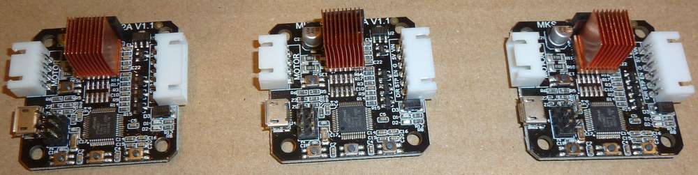
Thinking about that now, I suppose that in doing so there's some risk that, because of the weight, a lot of vibration might eventually rip the entire stepper chip off the board. Meh, hopefully it's moot: I'm etching PCB's, not milling stainless steel. If I were doing that instead, I can see the advantage of not having the stepper driver directly attached to the stepper motor.