CNC PCB milling
-
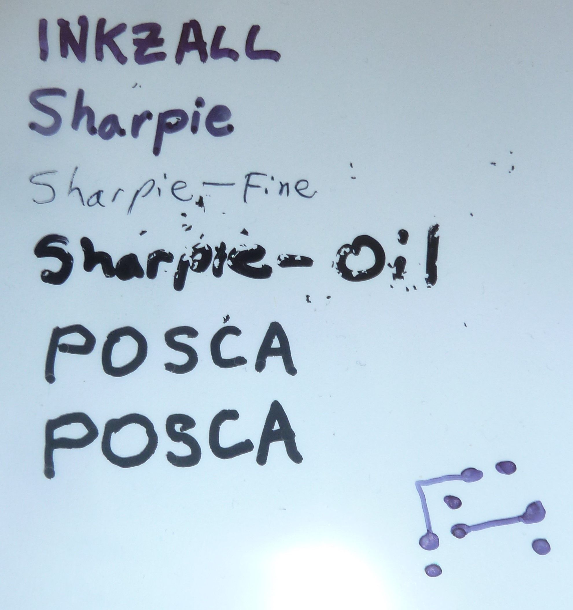
For purposes of solder masking, I compared a number of black markers for drawing on PP sheeting to see which would be the blackest and most opaque. I compared: Inkzall, regular Sharpie, Sharpie Oil, and POSCA (a Japanese paint pen). By reputation I had thought the POSCA would win, but by far the blackest and most opaque of the bunch was the Sharpie Oil. It appeared to be genuinely opaque. The Inkzall and the regular sharpie were not opaque at all.
-
For purposes of solder masking, I compared a number of black markers for drawing on PP sheeting to see which would be the blackest and most opaque. I compared: Inkzall, regular Sharpie, Sharpie Oil, and POSCA (a Japanese paint pen). By reputation I had thought the POSCA would win, but by far the blackest and most opaque of the bunch was the Sharpie Oil. It appeared to be genuinely opaque. The Inkzall and the regular sharpie were not opaque at all.
Reporting back: After letting it dry overnight, I discovered that the Sharpie-Oil apparently shrinks and then flakes off of the PP film:
Not sure if it behaves better with other films or not.
However, before it dries, it performs great, as seen below.
Here I am squishing solder mask between two thick sheets of glass:
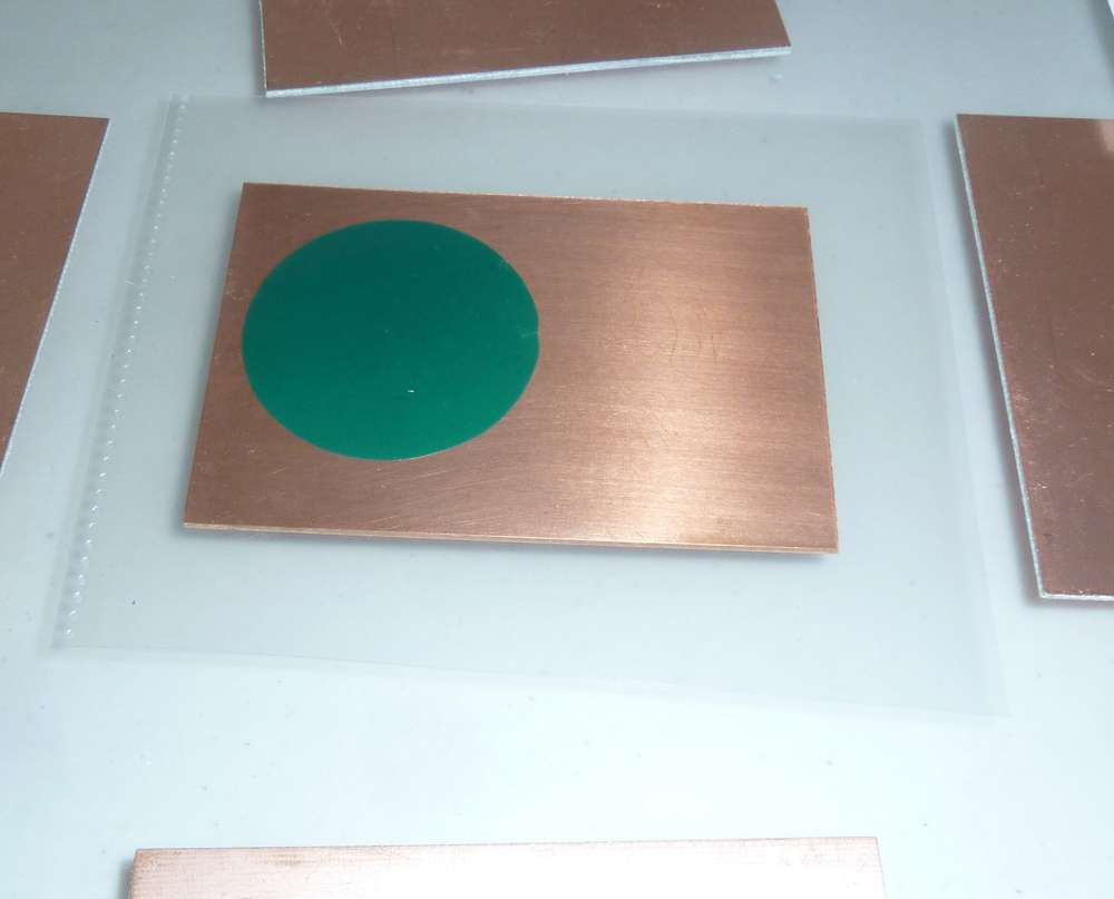
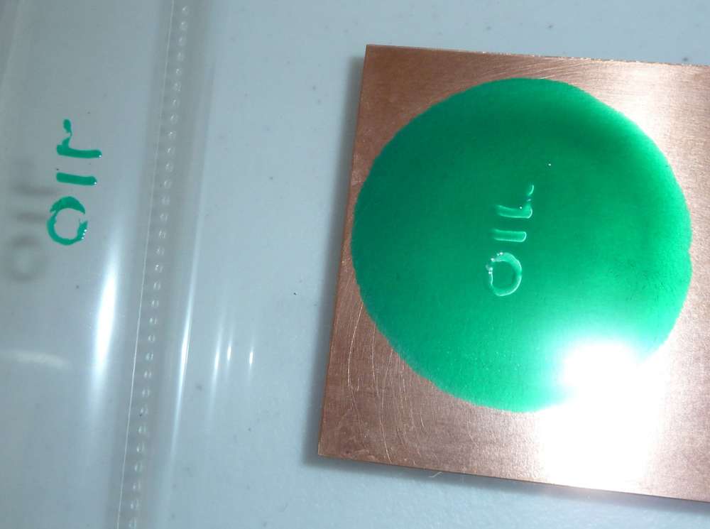
This technique seems to do a reasonably good job of producing a uniform thickness of the UV solder mask.Here I use a Sharpie Oil marker to print the word OIL and place it over the flattened solder mask before exposure to UV:
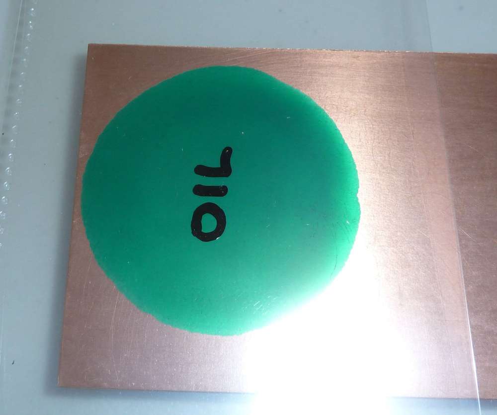
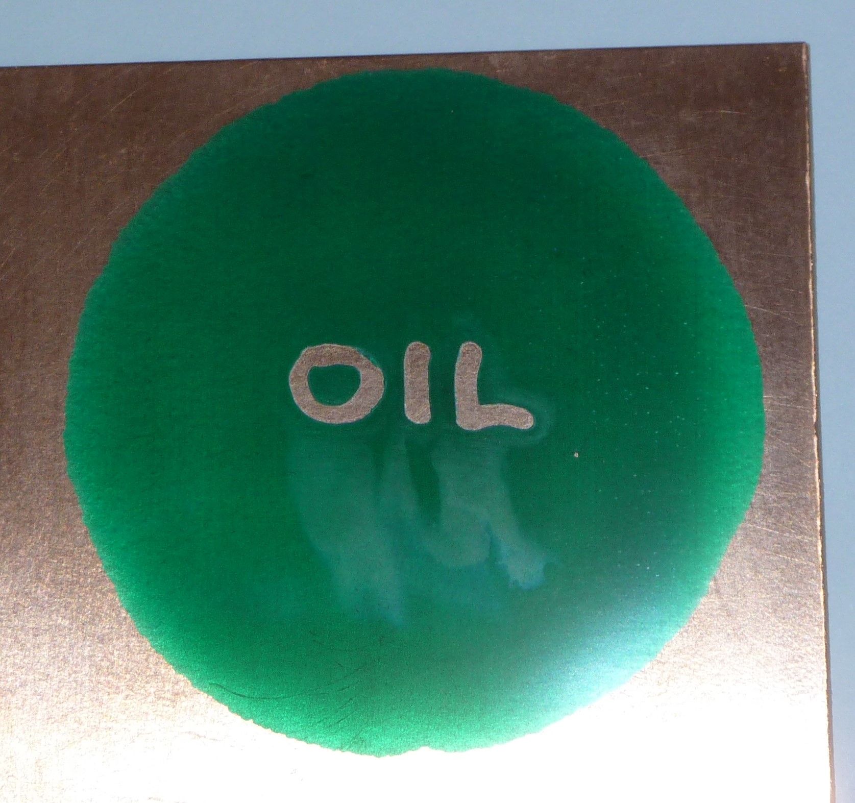
I exposed it to UV for a full 99 seconds, which may have completely cured the non-masked solder-mask. Here is how it looks after I removed the "OIL" mask:
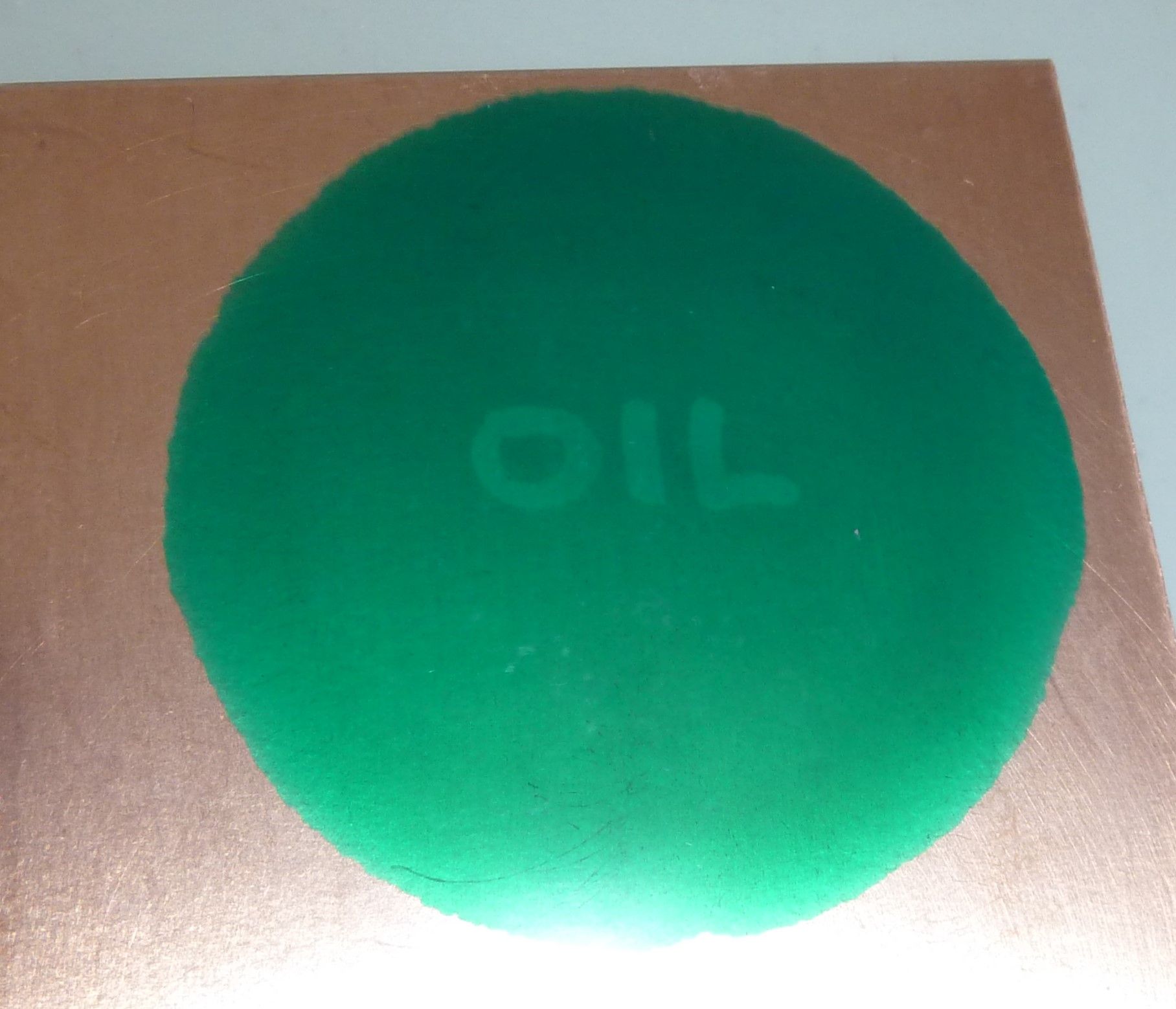
Here is how it looks after peeling back the top layer of PP film:
I then removed the uncured solder mask using IPA, after which I cured it some more under UV just to be sure:
As a first attempt, not bad! Using a high opacity mask probably helped quite a bit.
So, I guess now the question is: which inkjet ink/pigment or which laserjet toner has the highest opacity? For instance, there is this which claims to be: https://www.amazon.com/Ink-Dynasty-Resistant-Refillable-cartridge/dp/B00E3PAUXA
or this:
https://www.screenerschoice.com/index.php?route=product/product&product_id=157From the looks of it, the answer will be some kind of inkjet black pigment, which is consistent with the results I got from comparing ink pens vs paint pens above.
-
Reporting back: After letting it dry overnight, I discovered that the Sharpie-Oil apparently shrinks and then flakes off of the PP film:
Not sure if it behaves better with other films or not.
However, before it dries, it performs great, as seen below.
Here I am squishing solder mask between two thick sheets of glass:
This technique seems to do a reasonably good job of producing a uniform thickness of the UV solder mask.Here I use a Sharpie Oil marker to print the word OIL and place it over the flattened solder mask before exposure to UV:
I exposed it to UV for a full 99 seconds, which may have completely cured the non-masked solder-mask. Here is how it looks after I removed the "OIL" mask:
Here is how it looks after peeling back the top layer of PP film:
I then removed the uncured solder mask using IPA, after which I cured it some more under UV just to be sure:
As a first attempt, not bad! Using a high opacity mask probably helped quite a bit.
So, I guess now the question is: which inkjet ink/pigment or which laserjet toner has the highest opacity? For instance, there is this which claims to be: https://www.amazon.com/Ink-Dynasty-Resistant-Refillable-cartridge/dp/B00E3PAUXA
or this:
https://www.screenerschoice.com/index.php?route=product/product&product_id=157From the looks of it, the answer will be some kind of inkjet black pigment, which is consistent with the results I got from comparing ink pens vs paint pens above.
@NeverDie I saw an YouTube video screenprinting. That guy noticed that semi transparent sheets work better than transparent sheets. Ink holds better or something.
I can actually try this one out. Because afteral. We want that 0.4mm pitch right?
I just need to find something to put the paint on.
-
@NeverDie I saw an YouTube video screenprinting. That guy noticed that semi transparent sheets work better than transparent sheets. Ink holds better or something.
I can actually try this one out. Because afteral. We want that 0.4mm pitch right?
I just need to find something to put the paint on.
@Joerideman said in CNC PCB milling:
@NeverDie I saw an YouTube video screenprinting. That guy noticed that semi transparent sheets work better than transparent sheets. Ink holds better or something.
I can actually try this one out. Because afteral. We want that 0.4mm pitch right?
I just need to find something to put the paint on.
Which thing are you planning to try? Sharpie-Oil on a semi-transparent sheet, or the uv resistant inkjet ink, or...?
For enhanced laser printing I found this: https://ikonartstencil.com/toner-enhancement-spray/
though I have no idea how well, or even if, it works. -
I received some Sharpie-Oil "Extra Fine" pens. Testing them, they have a 1mm line width, so they'd be no good for filling in features smaller than that. AFAIK, they have the smallest tips in the Sharpie-Oil series.
I received the 16-bit closed-loop uStepper hardware from Denmark, so I'll be testing that sometime soon. I intend to use it on the z-axis, since accuracy on depth of cut is critical. If even this is still not enough, then I'll work harder to identify the source of the error and, if appropriate, consider stronger measures like low run-out collets, low-runout bits, ball-screws, tighter linear rails and/or tracking absolute position with a DRO and/or possibly a different spindle.
-
@Joerideman said in CNC PCB milling:
@NeverDie I saw an YouTube video screenprinting. That guy noticed that semi transparent sheets work better than transparent sheets. Ink holds better or something.
I can actually try this one out. Because afteral. We want that 0.4mm pitch right?
I just need to find something to put the paint on.
Which thing are you planning to try? Sharpie-Oil on a semi-transparent sheet, or the uv resistant inkjet ink, or...?
For enhanced laser printing I found this: https://ikonartstencil.com/toner-enhancement-spray/
though I have no idea how well, or even if, it works.@NeverDie inkjet printing on semi transparent sheets.
-
I've played around with the Ustepper-S now, and as near as I can tell, it is working correctly in closed-loop mode without issue. After the execution of each command, it shows error of 0.00, and it maintains closed loop operation to maintain its position even after the execution of the command, as it should. In my testing, Servo42A fails to do that, as well as having other problems, including lack of response to posted github issues.
Ustepper-S incorporates PID, so it should be able to do rapids and yet stop exactly where it should. Again, my initial impression is that seems to be the case.
I'm ordering UStepper-S for the x and y axis as well, which unfortunately will again take weeks to receive. However, I expect this will be the last stepper driver upgrade that I will ever need to do. If I later decide to upgrade to NEMA-23, the same UStepper-S can be used to drive it and only a different bracket would be needed to position it on the back of the NEMA-23.
-
I found a good "once and done" lubricant for my CNC called Krytox. It's made by Dupont, is non-toxic, never dries out, and is non-reactive with just about everything. It is more or less liquid teflon (PTFE). It comes in a wide spectrum of different viscosities. I'm using GPL105, but I think for a CNC one could argue for using a version that's a least slightly more viscous (i.e. GPL106 or higher).
There also exists grease versions of Krytox, so perhaps (?) that would be even better. In general, for any given lubricant, how does one decide what the right viscosity is to use?
-
@andrew Have you got your new 3020T yet? I intend to buy 3020 but there are a few variants in Aliexpress. Which site did you buy from? Can you share the link? Thank you for starting this thread.
@mlei30 This was my choice:
https://www.ebay.com/itm/CNC-Router-3020T-3-AXIS-USB-Graviermaschine-GraviergeräT-FräSmaschine/313030564524
It already arrived and I started to play with it.
I decided not use its Chinese controller software or Mach3 with parallel port connection, so it needs some upgrade before I can make the first tests with it.
There are tons of upgrade options to make it work with open source stuff. I almost ordered a TinyGv2 controller, but it turned out, that that CNC can be GRBL controlled over the parallel port. In such case,
original stepper and spindle drivers can be used as well.The problem is, that the research I found behind this was misleading and it contains inaccurate / improper details (or at least not exactly applicable to my HW version), so I had to re-execute the reverse engineering.
I'm about to finish it. At the moment I can control everything on the CNC from GRBL. Now I need to calibrate it and make the solution "solid/proper". I have hard time finding free time for this, but I hope that first test runs will be done soon.
I'll be back with the results soon (and I'm also planning to write a blogpost on the details later).
-
@mlei30 This was my choice:
https://www.ebay.com/itm/CNC-Router-3020T-3-AXIS-USB-Graviermaschine-GraviergeräT-FräSmaschine/313030564524
It already arrived and I started to play with it.
I decided not use its Chinese controller software or Mach3 with parallel port connection, so it needs some upgrade before I can make the first tests with it.
There are tons of upgrade options to make it work with open source stuff. I almost ordered a TinyGv2 controller, but it turned out, that that CNC can be GRBL controlled over the parallel port. In such case,
original stepper and spindle drivers can be used as well.The problem is, that the research I found behind this was misleading and it contains inaccurate / improper details (or at least not exactly applicable to my HW version), so I had to re-execute the reverse engineering.
I'm about to finish it. At the moment I can control everything on the CNC from GRBL. Now I need to calibrate it and make the solution "solid/proper". I have hard time finding free time for this, but I hope that first test runs will be done soon.
I'll be back with the results soon (and I'm also planning to write a blogpost on the details later).
- Does it use ball screws or trapezoidal ones?
- how stiff it is in X an Y directions?
(on my machine slight push on spindle, yields ~0.2mm of flex, and heavier one around 0.5mm, which is roughly precision I get when cutting plastic. For PCB routing error seems to stay within 0.2mm boundary) - how big is backlash
- screw (movement) linearity in X,Y planes
-
@andrew Looks as though your new nema steppers either have encoders or else those are knobs for manually jogging. Aside from that, it looks generally stiffer due to all metal with no plastic.
-
- Does it use ball screws or trapezoidal ones?
- how stiff it is in X an Y directions?
(on my machine slight push on spindle, yields ~0.2mm of flex, and heavier one around 0.5mm, which is roughly precision I get when cutting plastic. For PCB routing error seems to stay within 0.2mm boundary) - how big is backlash
- screw (movement) linearity in X,Y planes
@niallain it is 3020T which uses trapezoidal screws. "Z" uses ball screws.
you can check the "official" technical details on the item's specification (scroll down to the description then click on the "specification"):...
Driving units X axis: 1204 trapezoidal screws
Driving units Y axis: 1204 trapezoidal screws
Driving units Z axis: 1204 trapezoidal screws
...
Repeat accuracy: 0.05mm
...
Spindle precision: radial beat acuities 0.03 mm
...Note that none of these parameters above are confirmed. To be honest I don't have the right measurement tools for that, but the fine trace PCB samples will prove it, or not :)
-
@niallain it is 3020T which uses trapezoidal screws. "Z" uses ball screws.
you can check the "official" technical details on the item's specification (scroll down to the description then click on the "specification"):...
Driving units X axis: 1204 trapezoidal screws
Driving units Y axis: 1204 trapezoidal screws
Driving units Z axis: 1204 trapezoidal screws
...
Repeat accuracy: 0.05mm
...
Spindle precision: radial beat acuities 0.03 mm
...Note that none of these parameters above are confirmed. To be honest I don't have the right measurement tools for that, but the fine trace PCB samples will prove it, or not :)
@andrew said in CNC PCB milling:
@niallain it is 3020T which uses trapezoidal screws. "Z" uses ball screws.
you can check the "official" technical details on the item's specification (scroll down to the description then click on the "specification"):declared specs for mine were in the same ballpark as your's 3020T, modulo 8mm trapezoidal screw. But in reality that wasn't true at all, in my case cuplrit of the biggest error is the flex from the way screw nuts are attached to carriage, and the second/third are nonlinear screws (+-0.060mm) and backlash.
I'm ordered a 1204 ball screw kit for Y axis, to test how much it would reduce error.
PS:
As for testing, I just used regular digital calliper with 0.01mm resolution. -
@andrew said in CNC PCB milling:
@niallain it is 3020T which uses trapezoidal screws. "Z" uses ball screws.
you can check the "official" technical details on the item's specification (scroll down to the description then click on the "specification"):declared specs for mine were in the same ballpark as your's 3020T, modulo 8mm trapezoidal screw. But in reality that wasn't true at all, in my case cuplrit of the biggest error is the flex from the way screw nuts are attached to carriage, and the second/third are nonlinear screws (+-0.060mm) and backlash.
I'm ordered a 1204 ball screw kit for Y axis, to test how much it would reduce error.
PS:
As for testing, I just used regular digital calliper with 0.01mm resolution.@niallain said in CNC PCB milling:
in my case cuplrit of the biggest error is the flex from the way screw nuts are attached to carriage, and the second/third are nonlinear screws (+-0.060mm) and backlash.
I'm curious to know how is it that you're measuring those things? I'd like to quantify as many sources of error as possible, but I'm not sure how to go about it.
-
@niallain said in CNC PCB milling:
in my case cuplrit of the biggest error is the flex from the way screw nuts are attached to carriage, and the second/third are nonlinear screws (+-0.060mm) and backlash.
I'm curious to know how is it that you're measuring those things? I'd like to quantify as many sources of error as possible, but I'm not sure how to go about it.
@NeverDie How about a dial gauge in a magnetic mount attached to the spindle and measuring against x/y/z frame points, and a simple gcode like g0x100 g0x0 a hundred times? At least that's how I did it to check for lost steps.
-
@niallain said in CNC PCB milling:
in my case cuplrit of the biggest error is the flex from the way screw nuts are attached to carriage, and the second/third are nonlinear screws (+-0.060mm) and backlash.
I'm curious to know how is it that you're measuring those things? I'd like to quantify as many sources of error as possible, but I'm not sure how to go about it.
@NeverDie
I shoot a short clip to demo following measurements- backlash :
- flex: for example I used dial gauge, since my Y screw and table are currently dismantled, so I can't show how it's done with calliper on the table
- non-linearity is measured only on 1mm, with calliper or glass scale it would be possible to measure whole screw. (linuxcnc can use glass scale to map screw and then compensate, but I still don't have all components for it yet)
-
@NeverDie
I shoot a short clip to demo following measurements- backlash :
- flex: for example I used dial gauge, since my Y screw and table are currently dismantled, so I can't show how it's done with calliper on the table
- non-linearity is measured only on 1mm, with calliper or glass scale it would be possible to measure whole screw. (linuxcnc can use glass scale to map screw and then compensate, but I still don't have all components for it yet)
@niallain said in CNC PCB milling:
- non-linearity is measured only on 1mm, with calliper or glass scale it would be possible to measure whole screw. (linuxcnc can use glass scale to map screw and then compensate, but I still don't have all components for it yet)
That's quite an interesting result! I would not have imagined it would be so bad. What exactly is happening that causes this? Is the screw being wound up almost like a spring and some kind of stiction is causing the carriage to jump about like that? Is the anti-backlash nut causing it? Or is the stepper in fact not advancing as much as it should be due to no closed-loop feedback? What's the cause? How repeatable is it? i.e. does it jump about to the same amount in the same places each time it's cycled through the test, or does it vary each time the test is repeated?
It's a great advertisement for DRO's.
-
Reporting back: Regarding Sharpie-Oil pens, I found that it doesn't chip-off and disintegrate, even after letting it dry for a few days, if I write it onto inkjet transparency material instead of polypropylene:
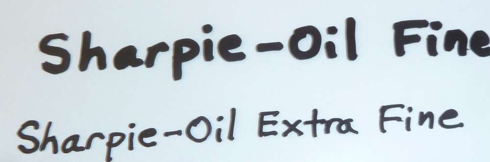
Because it's so opaque, especially when compared to other black pens, it's the best pen I've found. The linewidth of the "Sharpie-Oil Extra Fine" pen is about 1mm, though, so that precludes using it in a plotter if ultra fine detail is required.
Hello! It looks like you're interested in this conversation, but you don't have an account yet.
Getting fed up of having to scroll through the same posts each visit? When you register for an account, you'll always come back to exactly where you were before, and choose to be notified of new replies (either via email, or push notification). You'll also be able to save bookmarks and upvote posts to show your appreciation to other community members.
With your input, this post could be even better 💗
Register Login