DIY CNC mill from mainly salvaged and 3D printed parts

-
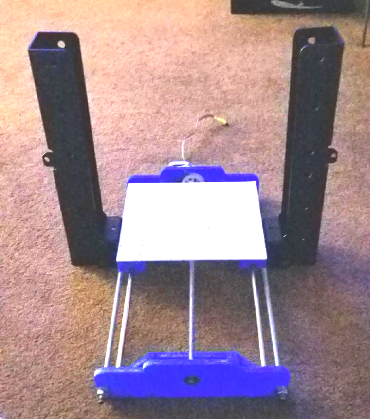
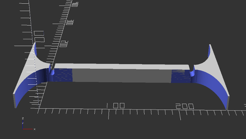
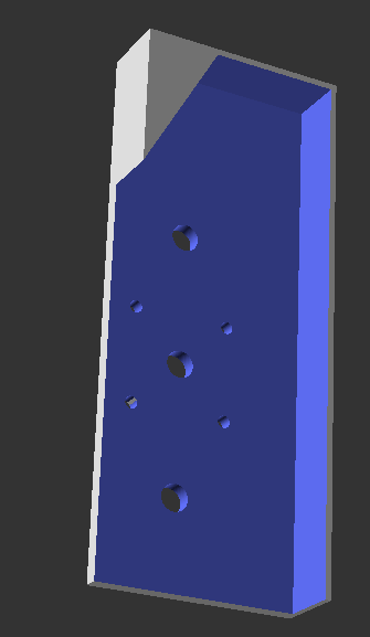
So I am toying with an idea for the uprights that will hold the X and Z axis. I salvaged these old DLP projector wall mount brackets and got 2 of these parts.
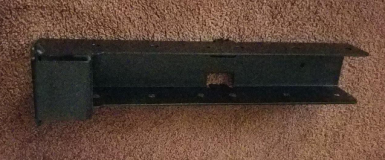
The idea is to have them mounted on the sides of the Y axis frame to hold the X and Z axis vertically. I guess my main issue that's leaning me away from using them is that they are quite heavy. If I do use them, I will have to design some sort of bracket that would mount them to the Y axis frame. One nice thing is that they have some holes pre-drilled at a few different levels that might help in mounting the cross rails for the X axis.
Ahhhh the dilemas of designing something from scratch....
Vera Plus running UI7 with MySensors, Sonoffs and 1-Wire devices
Visit my website for more Bits, Bytes and Ramblings from me: http://dan.bemowski.info/ -
So I am toying with an idea for the uprights that will hold the X and Z axis. I salvaged these old DLP projector wall mount brackets and got 2 of these parts.
The idea is to have them mounted on the sides of the Y axis frame to hold the X and Z axis vertically. I guess my main issue that's leaning me away from using them is that they are quite heavy. If I do use them, I will have to design some sort of bracket that would mount them to the Y axis frame. One nice thing is that they have some holes pre-drilled at a few different levels that might help in mounting the cross rails for the X axis.
Ahhhh the dilemas of designing something from scratch....
@dbemowsk Looks promising. The Trinus 3D printer (http://www.trinus3d.com/) went all steel on everything, and maker's muse attributed that as the reason why it could print in such fine detail.
As to the closed-loop versus open-loop feedback, I had written about that in the CNC PCB milling thread, but @andrew didn't think it was needed, so it probably isn't. But anyway, if you look inside, say, modern inkjet printers, they don't even use stepper motors anymore for head positioning in the x-axis. Instead, they rely on a kind of quadrature linear tape that it reads to position the head very precisely. Well, why? In the past, they used to use stepper motors for that. Is it purely a manufacturing cost saving, or did they need to go that route to get more precise control as DPI's increased?
So, since you're salvaging parts anyway, you could extract such linear positioning tapes from used inkjet printers (which are practically free, because people upgrade and throw out their old equipment because it's so cheap now). Just a thought....
-
@dbemowsk Looks promising. The Trinus 3D printer (http://www.trinus3d.com/) went all steel on everything, and maker's muse attributed that as the reason why it could print in such fine detail.
As to the closed-loop versus open-loop feedback, I had written about that in the CNC PCB milling thread, but @andrew didn't think it was needed, so it probably isn't. But anyway, if you look inside, say, modern inkjet printers, they don't even use stepper motors anymore for head positioning in the x-axis. Instead, they rely on a kind of quadrature linear tape that it reads to position the head very precisely. Well, why? In the past, they used to use stepper motors for that. Is it purely a manufacturing cost saving, or did they need to go that route to get more precise control as DPI's increased?
So, since you're salvaging parts anyway, you could extract such linear positioning tapes from used inkjet printers (which are practically free, because people upgrade and throw out their old equipment because it's so cheap now). Just a thought....
@neverdie I get what you are going for now with the closed loop feedback. The problem in it is that I plan to use the standard GRBL firmware to run this, and if I were to go with that approach, I would probably have to modify the GRBL firmware to accommodate that as I don't think it is something native to it. If I am wrong on that, please correct me. Along with that, I don't know if I would have to make modifications to the CNC shield to do it, or if I could tone out some available pins to use for that. I don't know how encoders like that would work with steppers anyway. When steppers move one position, that equates to a certain distance based on it's direct drive, or as in my case the gear ratio. The fine encoder discs or strips used in ink jet printers may be able to be matched to the steps of the stepper, but if one step of the motor matched to a half step position on the encoder, that could throw things off slightly. I think the encoders would only be needed if the steppers were prone to missing steps, which if they are set up correctly, shouldn't. I think the steppers will be accurate enough for this application. Besides, the extra work it would take to salvage the parts and implement them into the design would be more work than I would care to take on at this point.
-
Just a concern, the MDF plate could/might contains sand particles (manufactures use cheap wood materials), so don't let your expensive endmills cut down to the MDF as this will ware out the sharp endmills
-
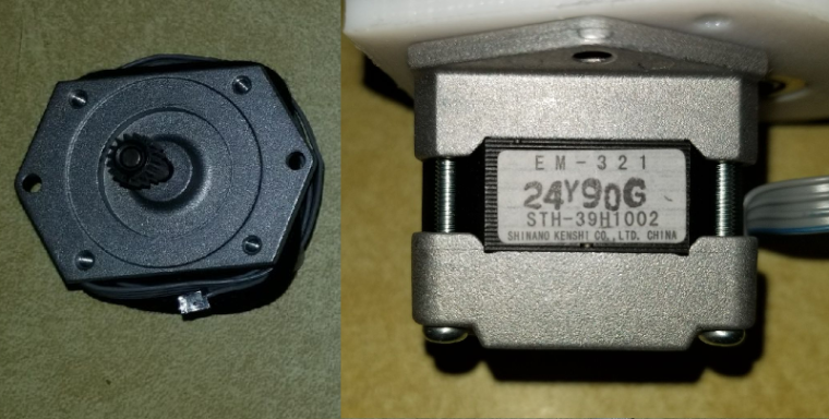
After some further review and thought, I am thinking of just getting a set of 3 motors. I figure that way I have a matched set and I am not fighting things like too slow speed on one axis that is fighting the others when milling a job. This will require some modifications to my current Y axis, but I will only have to modify the bracket on the motor side which won't be hard at all.
The question I have is, will these motors be good enough? They are 0.9° which is 400 steps/rev vs the somewhat standard 1.8° @200 steps/rev. They are 65 oz-in bipolar motors.
https://www.ebay.com/itm/3pcs-NEMA17-0-9-Stepper-Motor-65-oz-in-Robot-Reprap-Makerbot-Arduino/122627614293?hash=item1c8d2ce655:g:z1MAAOSwX9FZH06R -
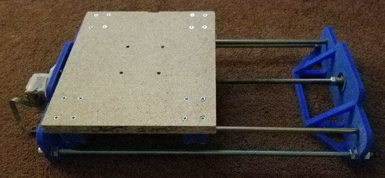
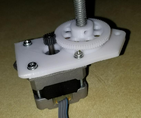
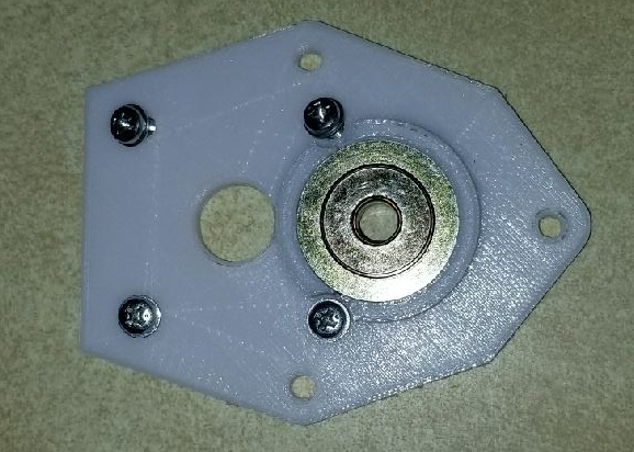
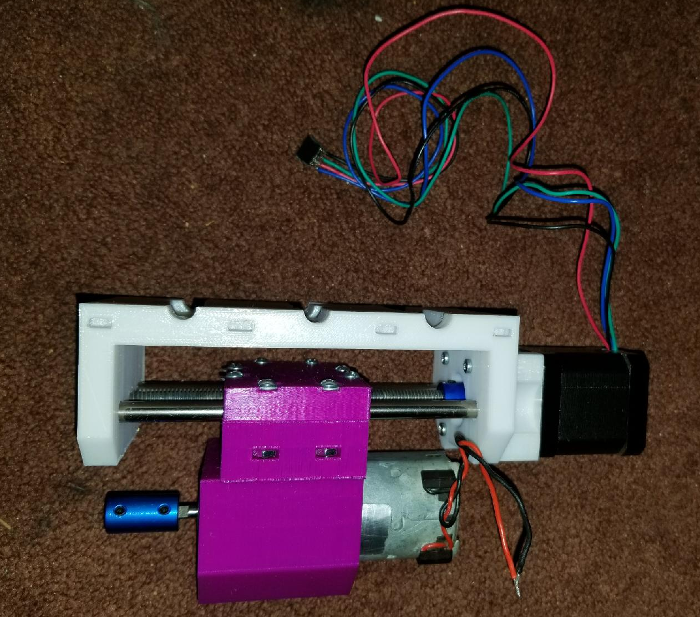
Well, haven't posted to my thread in a while so I thought I'd give an update. I am close to having the Z axis complete. Below are some pictures of the spindle assembly as I have it right now.
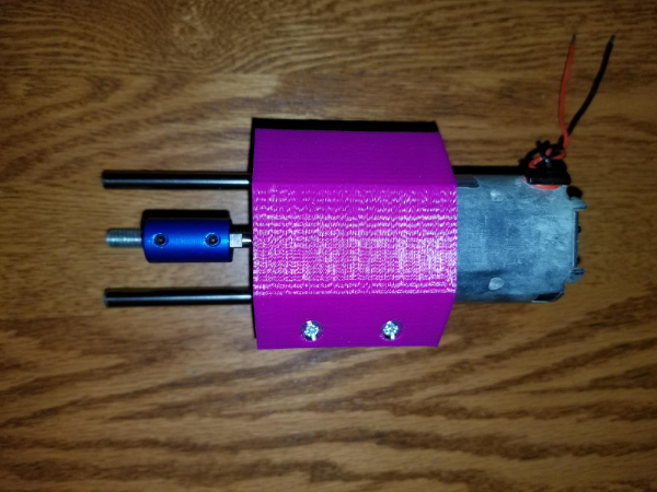
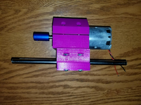
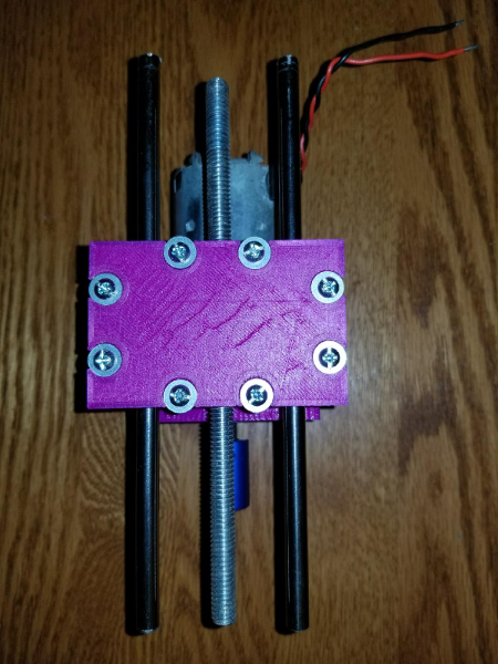
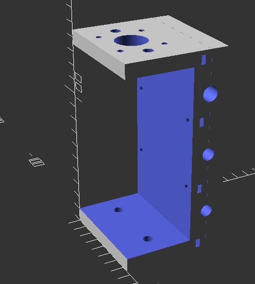
This is the next part in line to be printed is the Z axis motor mount and X axis carriage. Below is a pic of the design. I have it printing now and there is 11 hours to go in the print. The longest printed part so far.
-
After some further review and thought, I am thinking of just getting a set of 3 motors. I figure that way I have a matched set and I am not fighting things like too slow speed on one axis that is fighting the others when milling a job. This will require some modifications to my current Y axis, but I will only have to modify the bracket on the motor side which won't be hard at all.
The question I have is, will these motors be good enough? They are 0.9° which is 400 steps/rev vs the somewhat standard 1.8° @200 steps/rev. They are 65 oz-in bipolar motors.
https://www.ebay.com/itm/3pcs-NEMA17-0-9-Stepper-Motor-65-oz-in-Robot-Reprap-Makerbot-Arduino/122627614293?hash=item1c8d2ce655:g:z1MAAOSwX9FZH06R@dbemowsk said in DIY CNC mill from mainly salvaged and 3D printed parts:
I figure that way I have a matched set and I am not fighting things like too slow speed on one axis that is fighting the others when milling a job.
From what I've read, your GRBL controller would compensate, as it knows the speed of each motor (well, after you tell it, that is).
-
@dbemowsk said in DIY CNC mill from mainly salvaged and 3D printed parts:
I figure that way I have a matched set and I am not fighting things like too slow speed on one axis that is fighting the others when milling a job.
From what I've read, your GRBL controller would compensate, as it knows the speed of each motor (well, after you tell it, that is).
@neverdie said in DIY CNC mill from mainly salvaged and 3D printed parts:
From what I've read, your GRBL controller would compensate, as it knows the speed of each motor (well, after you tell it, that is).
I figured that, but I was having trouble with a couple of the steppers that I was trying to use. Couldn't seem to get them to run reliably from the GRBL controller. The other part would have been figuring out a drive system for them as they all had geared heads. I would have had to figure out a gearing and mounting system. The motors I got were only $33 US, so basically $11/motor, so not a bad price, and I can direct couple them to the threaded rods making things easier.
-
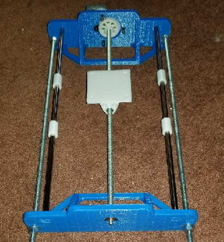
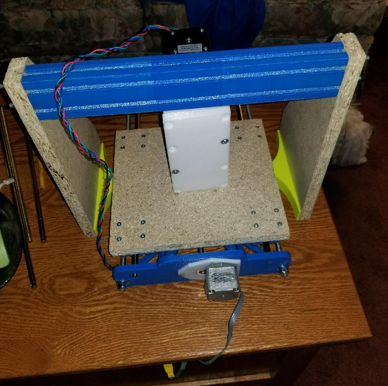
So I would call today's part of the build pretty significant. I have the Z axis mostly assembled and did a drive test. Below are some pics of the assembly.
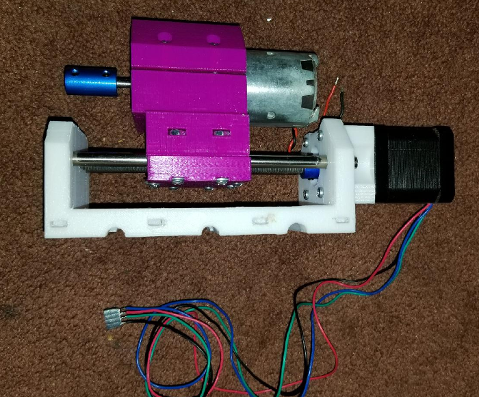
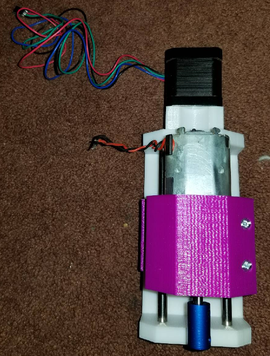
Here is the assembly taking it's first steps. It still needs some adjustment, but from what I am seeing, things should work. The next part of the build is going to be getting the uprights made that will hold the X axis rods and drive assembly. Once that is done, I should be able to do some more solid testing and calibration.
https://www.youtube.com/watch?v=XR7zPx8NVN8 -
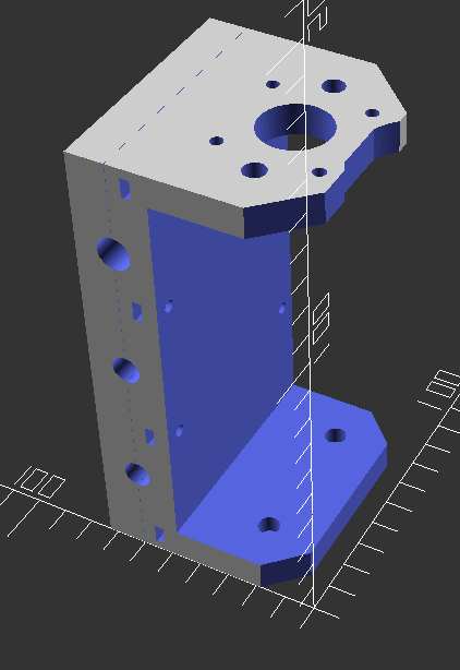
As some of you may have noticed, based on the earlier cad drawing, I had to make some adjustments to the large white bracket. The adjustments were there to let the spindle motor pass by the bracket. On the first attempt, the back of the spindle motor was hitting the bracket restricting travel. Also, the lower lip of the spindle motor assembly was hitting the lower part of the bracket. A few tweaks later and this was born.
-
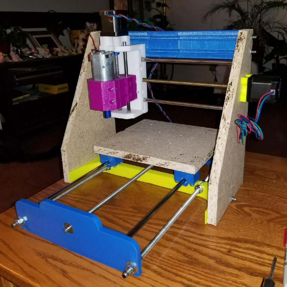
So, the project is nearing completion. I have an amalgam of colors used in the setup as I was trying to use up some rolls of plastic that I had on hand. I now have a gantry assembly that is held together at the top with some 3D printed T-Slot channel that was part of a failed print. There are 3 pieces strung together with some 10-24 threaded rods run through the center holes.
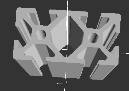
The bottom is strung together with a custom 3D printed I support that also has a piece of 10-24 threaded rod through it. That too was done in two pieces because I could not fit the whole thing on my print bed.
I am in the process of printing the drill guides to drill the holes in the MDF sides that will hold the smooth rods and the X axis stepper.
Here are the latest pics of the assembly so far.
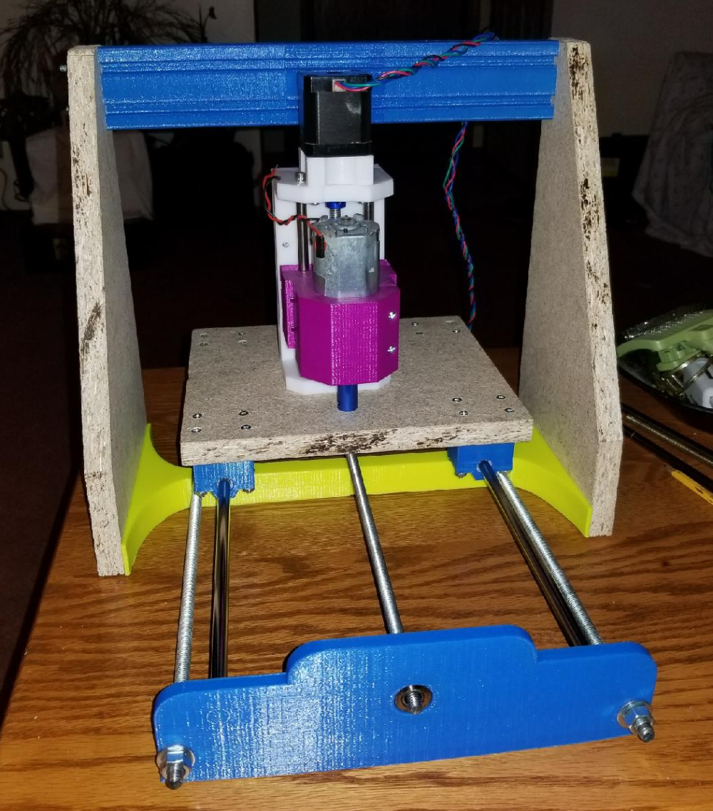
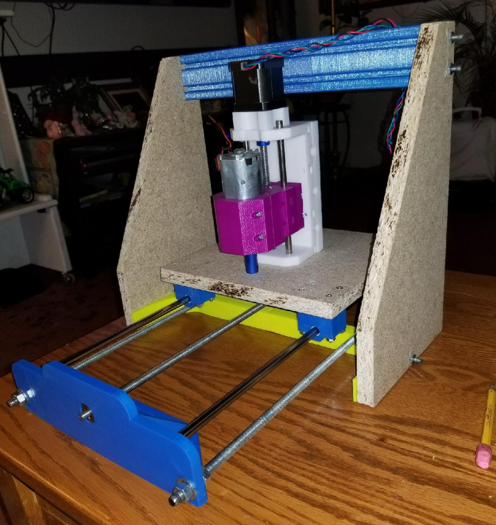
Once I have the gantry X axis rods in place with the Z axis carriage, I will then be able to do a full test of the electronics. I opted for now to keep the salvaged Y axis motor assembly since I had that working. Once I have everything working, I will post a video.
Vera Plus running UI7 with MySensors, Sonoffs and 1-Wire devices
Visit my website for more Bits, Bytes and Ramblings from me: http://dan.bemowski.info/ -
So, the project is nearing completion. I have an amalgam of colors used in the setup as I was trying to use up some rolls of plastic that I had on hand. I now have a gantry assembly that is held together at the top with some 3D printed T-Slot channel that was part of a failed print. There are 3 pieces strung together with some 10-24 threaded rods run through the center holes.
The bottom is strung together with a custom 3D printed I support that also has a piece of 10-24 threaded rod through it. That too was done in two pieces because I could not fit the whole thing on my print bed.
I am in the process of printing the drill guides to drill the holes in the MDF sides that will hold the smooth rods and the X axis stepper.
Here are the latest pics of the assembly so far.
Once I have the gantry X axis rods in place with the Z axis carriage, I will then be able to do a full test of the electronics. I opted for now to keep the salvaged Y axis motor assembly since I had that working. Once I have everything working, I will post a video.
-
If it doesn't work out, maybe you will want to build an MPCNC instead?
-
@dbemowsk MDF? That is chipboard or particle board, no?
I very much doubt you will get sufficient rigidity even were you to glue/screw ribs on those side plates, and as a material it behaves badly with vibrating bolts etc...@zboblamont I'll see how it goes. It is a big experiment at this point. If it doesn't work out I may be able to have a frame milled pretty cheap. I work for our local school district and I know the shop teachers at our high school that run the large CNC mill that they have. I may be able to have them mill me some parts. I do have all the needed steppers and things, I may just need a frame, worst case.
-
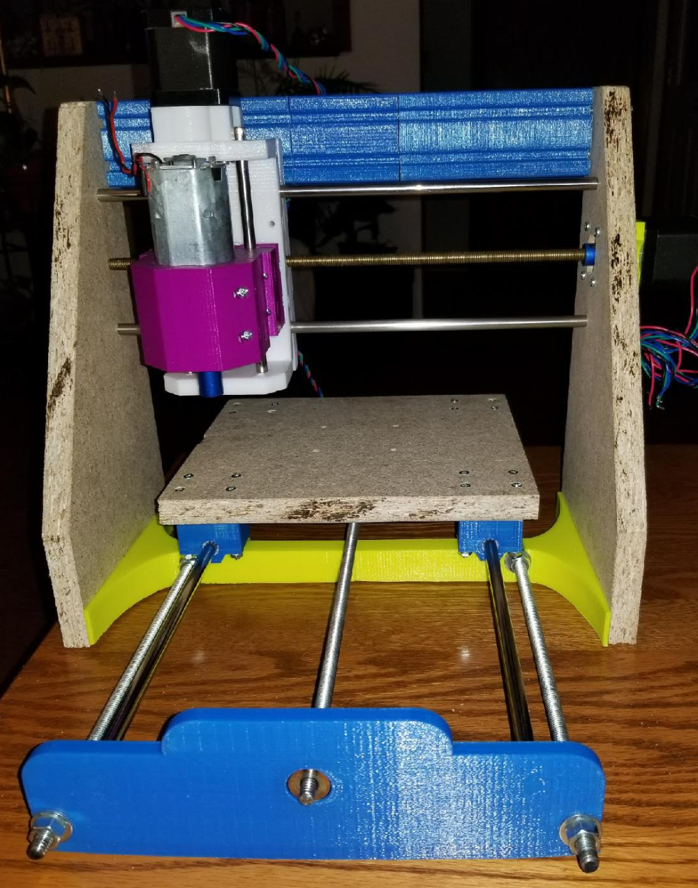
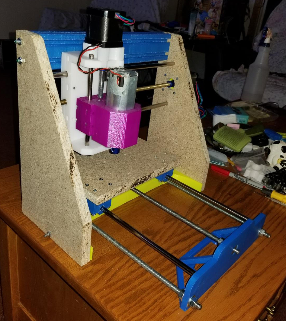
So the CNC is near ready for testing. I need to solder a connector on to the X axis stepper and I should be able to run some tests. I think the next step is going to be figuring out how to calibrate the GRBL controller.
Here are some pics of the build so far.
Vera Plus running UI7 with MySensors, Sonoffs and 1-Wire devices
Visit my website for more Bits, Bytes and Ramblings from me: http://dan.bemowski.info/ -
So the CNC is near ready for testing. I need to solder a connector on to the X axis stepper and I should be able to run some tests. I think the next step is going to be figuring out how to calibrate the GRBL controller.
Here are some pics of the build so far.
@dbemowsk A+ for sticking with it all the way to completion.
The main calibration number will probably be the revolutions per inch for each of the axises (axi?). From there you can start air carving.