Cannot get RFM69HW connection between ESP8266GW and Pro Mini Sensor


  • Hi, I build my first two test devices on breadboard a while ago, one Wemos D1 mini and one Arduino Pro Mini.
    The D1 is flashed with the GatewayESP8266MWTTClient sketch. The Wifi and MQTT connecion works fine, and it seems to start listening:

    59 MCO:BGN:INIT GW,CP=RRNGE---,VER=2.2.0
    63 TSF:LRT:OK
    64 TSM:INIT
    65 TSF:WUR:MS=0
    68 TSM:INIT:TSP OK
    70 TSM:INIT:GW MODE
    72 TSM:READY:ID=0,PAR=0,DIS=0
    74 MCO:REG:NOT NEEDED
    scandone
    scandone
    state: 0 -> 2 (b0)
    state: 2 -> 3 (0)
    state: 3 -> 5 (10)
    add 0
    aid 6
    cnt 
    
    connected with DiscoveryOneIoT, channel 1
    dhcp client start...
    ip:10.165.20.87,mask:255.255.240.0,gw:10.165.16.1
    578 GWT:TPC:CONNECTING...
    580 GWT:TPC:IP=10.165.20.87
    583 MCO:BGN:STP
    5
    5
    15
    15
    584 MCO:BGN:INIT OK,TSP=1
    588 GWT:TPC:IP=10.165.20.87
    590 GWT:RMQ:MQTT RECONNECT
    664 GWT:RMQ:MQTT CONNECTED
    667 GWT:TPS:TOPIC=home-le/rfm69gateway/out/0/255/0/0/18,MSG SENT
    pm open,type:2 0
    

    The numbers after 583 are Serial.prints of D1, D8 and the respective MySensors defines, indicating that I actually configured the correct pins - the connection tutorial seems to list a wrong IRQ port, so I became very careful with this stuff. Or rather, the default port 2=GPIO2=D4 in the library is badly chosen, because it is a boot pin of the ESP and it didn't actually boot when I connected it.

    The Pro Mini is flashed with the light sensor sketch (because it just reads an analog pin), and tries to connect but seems to fail. The GW does not report anything at the same time:

     __  __       ____
    |  \/  |_   _/ ___|  ___ _ __  ___  ___  _ __ ___
    | |\/| | | | \___ \ / _ \ `_ \/ __|/ _ \| `__/ __|
    | |  | | |_| |___| |  __/ | | \__ \  _  | |  \__ \
    |_|  |_|\__, |____/ \___|_| |_|___/\___/|_|  |___/
            |___/                      2.2.0
    
    16 MCO:BGN:INIT NODE,CP=RRNNA---,VER=2.2.0
    26 TSM:INIT
    28 TSF:WUR:MS=0
    30 TSM:INIT:TSP OK
    32 TSM:FPAR
    1253 TSF:MSG:SEND,255-255-255-255,s=255,c=3,t=7,pt=0,l=0,sg=0,ft=0,st=OK:
    3262 !TSM:FPAR:NO REPLY
    3264 TSM:FPAR
    4483 TSF:MSG:SEND,255-255-255-255,s=255,c=3,t=7,pt=0,l=0,sg=0,ft=0,st=OK:
    6492 !TSM:FPAR:NO REPLY
    6494 TSM:FPAR
    7712 TSF:MSG:SEND,255-255-255-255,s=255,c=3,t=7,pt=0,l=0,sg=0,ft=0,st=OK:
    9721 !TSM:FPAR:NO REPLY
    9723 TSM:FPAR
    10942 TSF:MSG:SEND,255-255-255-255,s=255,c=3,t=7,pt=0,l=0,sg=0,ft=0,st=OK:
    12951 !TSM:FPAR:FAIL
    12953 TSM:FAIL:CNT=1
    12955 TSM:FAIL:DIS
    12957 TSF:TDI:TSL
    

    I am using the following defines in both sketches before including MySensors.h:

    #define MY_RADIO_RFM69
    #define MY_RFM69_FREQUENCY (RFM69_868MHZ)
    #if defined ARDUINO_ARCH_ESP8266
    #define MY_RFM69_IRQ_PIN D1
    #define MY_RFM69_CS_PIN D8
    #elif defined ARDUINO_ARCH_AVR
    #define MY_RFM69_IRQ_PIN 2
    #define MY_RFM69_CS_PIN 10
    #endif
    #define MY_IS_RFM69HW
    #define MY_RFM69_NETWORKID (83)
    #define MY_RFM69_MAX_POWER_LEVEL_DBM (10u)
    //#define MY_RFM69_ENABLE_ENCRYPTION
    

    Without touching the hardware, I can a reliable connection when I flash the rf69_server/client examples of the RadioHead library, with RH_RF69 rf69(D8, D1); on the D1 and RH_RF69 rf69; on the Pro Mini, so on the hardware side, everything seems to be fine.

    I did run the SecurityPersonalizer sketch on both devices, when I thought this would work with less issues, seting soft signing and a matching AES key, but as you can see above, I did not enable encryption. I am only mentioning this, because at least on the ESP the MySensors library seems to have issues with persistent configurations. The SecurityPersonalizer for example alwas tries to connect to my Wifi on the ESP.

    I am pretty much out of ideas. Anyone?

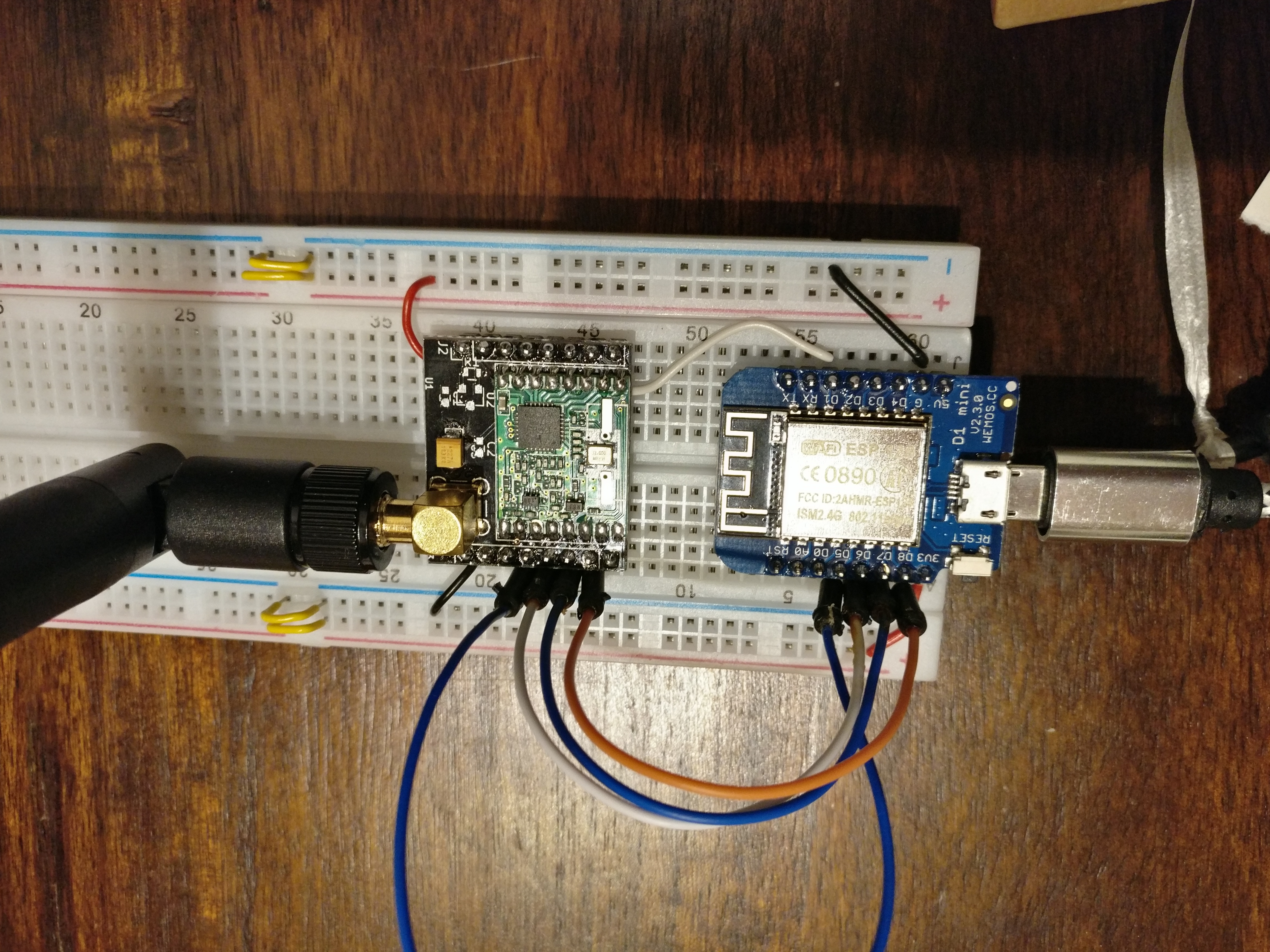
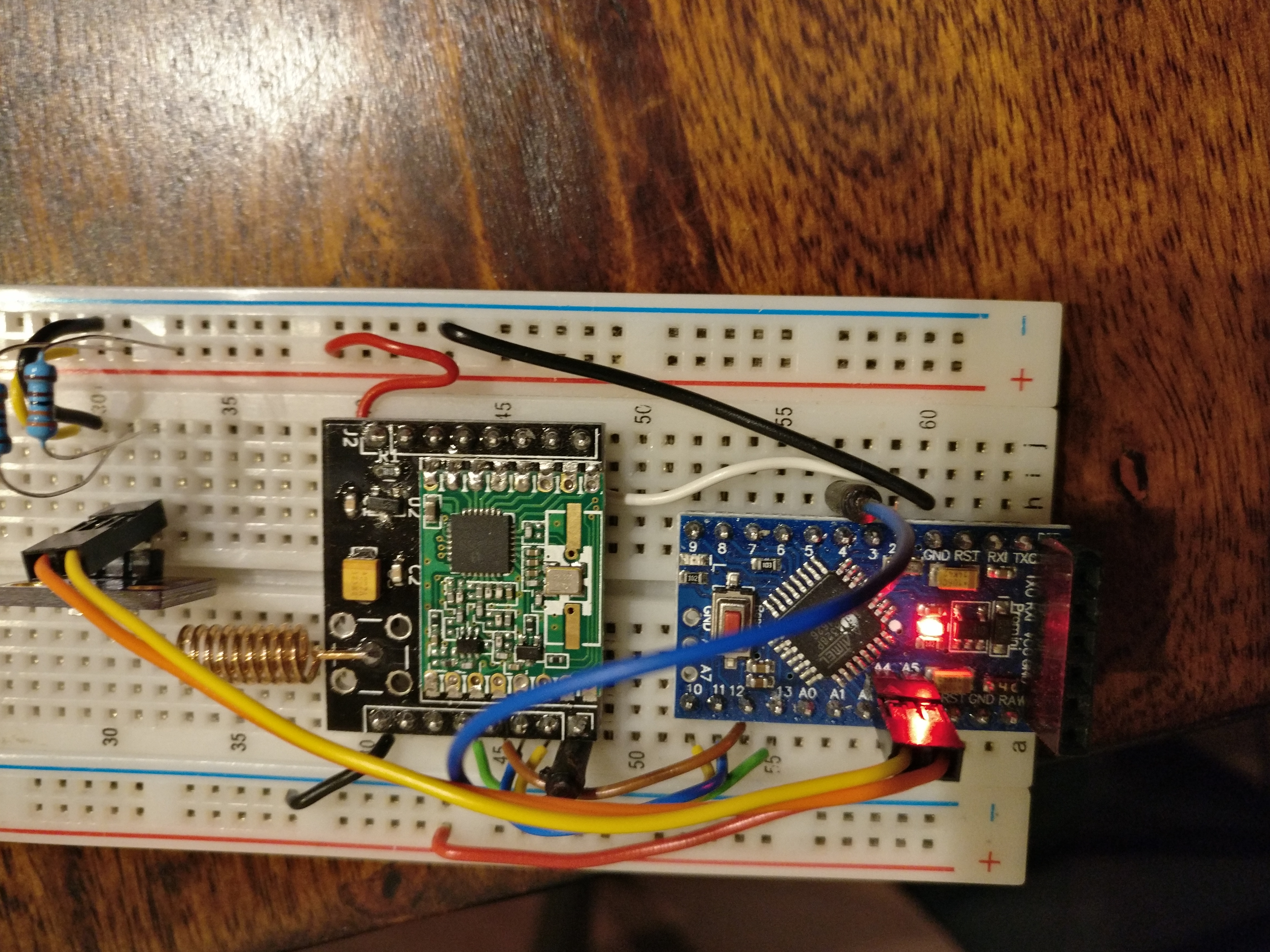
    Here are some picture, not sure how helpful they are:
    1_1520021752562_IMG_20180302_211301.jpg 0_1520021752562_IMG_20180302_211420.jpg


  • Mod

    @elcaron the only thing I can think of is that the helical antenna is positioned very close to the breadboard, which has lots of metal that will interfere with the signal. You could try bending the antenna so it is upright. You could also try moving the devices further apart - especially the high power radios have a tendency to overpower the receiver if the sender is too close.

    But since sending and receiving works with radiohead, antenna position should not be the problem. Are you using the same output power?


  • Contest Winner

    @elcaron you have disabled encryption on both the node and the GW? If one of them has it enabled and the other not, they can't communicate.
    As for the personalizer and the esp, others have problem as well communicating with the atsha. Currently the personalizer has no esp specific management so wifi is not handled at all for instance.
    But you can use the password flags for security to test without having to personalize anything.


  • Do you mean this with output power?:

    @elcaron said in Cannot get RFM69 connection between ESP8266GW and Pro Mini Sensor:

    #define MY_RFM69_MAX_POWER_LEVEL_DBM (10u)

    I use exactly the same includes in both sketches, hence the precompiler if statement. Apart from that, there are of course the very different antennas, but with Radiohead, this test setup has a range and wall penetration that can at least rival my 2.4GHz Wifi (works through a concrete ceiling + wall). I have also moved the sensor a few meters away from the gateway now, no difference.

    you have disabled encryption on both the node and the GW? If one of them has it enabled and the other not, they can't communicate.

    As I said, I use exactly the same precompiler defines shown above in both sketches. I have tried it with both encryption activated and deactivated. I tested how encryption behaves using the Radiohead lib and understand that it has to match.
    BTW, I am the guy from two weeks ago who had problems with the ATSHA, but I decided to first get the basic stuff sorted 🙂

    Guess I have to dig out another Pro Mini to test if at least that communication works.


  • Contest Winner

    @elcaron ah, thought it sounded familiar 🙂
    Then I think we can rule out the security complications.

    Have you tested to move the nodes further apart? I have noticed that if they are too close, or within a certain range in close proximity, rf signal decreases significantly.


  • In the last test , they where 5m apart. With radiohead, they work both 20cm away and 20m away with one concrete wall and one ceiling.
    Seems like I have to decide soon if it is easier to dust off the logic analyser and find out what is going on, or to implement HMAC with Radiohead 🙂


  • Mod

    @elcaron sorry for being unclear. I was asking if you used 10dBm output power when testing with the radiohead client/server.

    If you are using less power with radiohead, that could be the answer. As I said, too much power often causes problems.


  • Looking at the Radiohead sketch

    rf69.setTxPower(14, true);
    

    it rather looks like I used it with more power. But then also, I tested Radiohead between 50cm and the abovementioned 20m+wall+ceiling, while ich tested MySensors with 10dB at 50cm and 5m LoS


  • Mod

    Why don't you leave atc adjusting TX power automatically?


  • As far as I understand the documentation, I still have ATC enabled, as I did not set #define MY_RFM69_ATC_MODE_DISABLED

    With MY_RFM69_MAX_POWER_LEVEL_DBM, i could go up to 14dBm for my local legislation, but I stayed a little below it, because I wasn't sure about the antenna gain on the gateway. Do you actually think 10mW compared to the legally possible 25mW are the problem, given that I test at 50cm and 5m line of sight?


  • Mod

    I was just asking since I saw you playing with TX power. Maybe you could give a try without touching the TX power. BTW did you set a node ID on the node?


  • Ok, I have quoted that line for completeness. No change. I have also set MY_SIGNING_SIMPLE_PASSWD on both nodes to try to rule out issues with encryption:

    These are my radio related precompiler statements right now:

    #define MY_RADIO_RFM69
    #define MY_RFM69_FREQUENCY (RFM69_868MHZ)
    #if defined ARDUINO_ARCH_ESP8266
    #define MY_RFM69_IRQ_PIN D1
    #define MY_RFM69_CS_PIN D8
    #elif defined ARDUINO_ARCH_AVR
    #define MY_RFM69_IRQ_PIN 2
    #define MY_RFM69_CS_PIN 10
    #endif
    #define MY_IS_RFM69HW
    #define MY_RFM69_NETWORKID (83)
    #define MY_SIGNING_SIMPLE_PASSWD "MyInsecurePassword"
    //#define MY_RFM69_MAX_POWER_LEVEL_DBM (10u)
    //#define MY_RFM69_ENABLE_ENCRYPTION
    //#define MY_RFM69_SPI_SPEED (800000ul)
    

  • Contest Winner

    @elcaron looked like you had encryption disabled previously, so I don't think any security feature is the cause of these issues. Unless you had it defined mysensors.h by accident.


  • @anticimex Didn't expect that either, but better safe than sorry.


  • Contest Winner

    @elcaron true, but by using the password flag you actually enable security, so it introduced yet another variable. But since you did not see any difference, I think it is rf related as well.


  • For further testing, I have set up two Pro Mini now. With these, I get some communication.

    SerialGateway:

    0;255;3;0;9;0 MCO:BGN:INIT GW,CP=RRNGA---,VER=2.2.0
    0;255;3;0;9;4 TSM:INIT
    0;255;3;0;9;6 TSF:WUR:MS=0
    0;255;3;0;9;10 TSM:INIT:TSP OK
    0;255;3;0;9;14 TSM:INIT:GW MODE
    0;255;3;0;9;16 TSM:READY:ID=0,PAR=0,DIS=0
    0;255;3;0;9;22 MCO:REG:NOT NEEDED
    0;255;3;0;14;Gateway startup complete.
    0;255;0;0;18;2.2.0
    0;255;3;0;9;28 MCO:BGN:STP
    0;255;3;0;9;34 MCO:BGN:INIT OK,TSP=1
    0;255;3;0;9;3753 TSF:MSG:READ,255-255-255,s=255,c=3,t=7,pt=0,l=0,sg=0:
    0;255;3;0;9;3760 TSF:MSG:BC
    0;255;3;0;9;3764 TSF:MSG:FPAR REQ,ID=255
    0;255;3;0;9;3768 TSF:CKU:OK,FCTRL
    0;255;3;0;9;3770 TSF:MSG:GWL OK
    0;255;3;0;9;5695 TSF:MSG:SEND,0-0-255-255,s=255,c=3,t=8,pt=1,l=1,sg=0,ft=0,st=OK:0
    0;255;3;0;9;6993 TSF:MSG:READ,255-255-0,s=192,c=3,t=3,pt=0,l=0,sg=0:
    255;192;3;0;3;
    0;255;3;0;9;9218 TSF:MSG:READ,255-255-0,s=161,c=3,t=3,pt=0,l=0,sg=0:
    255;161;3;0;3;
    0;255;3;0;9;11239 TSF:MSG:READ,255-255-0,s=79,c=3,t=3,pt=0,l=0,sg=0:
    255;79;3;0;3;
    0;255;3;0;9;13258 TSF:MSG:READ,255-255-0,s=49,c=3,t=3,pt=0,l=0,sg=0:
    255;49;3;0;3;
    

    Client:

    16 MCO:BGN:INIT NODE,CP=RRNNA---,VER=2.2.0
    26 TSM:INIT
    28 TSF:WUR:MS=0
    30 TSM:INIT:TSP OK
    32 TSM:FPAR
    1253 TSF:MSG:SEND,255-255-255-255,s=255,c=3,t=7,pt=0,l=0,sg=0,ft=0,st=OK:
    1374 TSF:MSG:READ,0-0-255,s=255,c=3,t=8,pt=1,l=1,sg=0:0
    1380 TSF:MSG:FPAR OK,ID=0,D=1
    1576 TSF:MSG:READ,0-0-255,s=255,c=3,t=8,pt=1,l=1,sg=0:0
    1779 TSF:MSG:READ,0-0-255,s=255,c=3,t=8,pt=1,l=1,sg=0:0
    3262 TSM:FPAR:OK
    3262 TSM:ID
    3264 TSM:ID:REQ
    3274 TSF:MSG:SEND,255-255-0-0,s=192,c=3,t=3,pt=0,l=0,sg=0,ft=0,st=OK:
    5281 TSM:ID
    5281 TSM:ID:REQ
    5494 TSF:MSG:SEND,255-255-0-0,s=161,c=3,t=3,pt=0,l=0,sg=0,ft=0,st=OK:
    7503 TSM:ID
    7503 TSM:ID:REQ
    7514 TSF:MSG:SEND,255-255-0-0,s=79,c=3,t=3,pt=0,l=0,sg=0,ft=0,st=OK:
    9521 TSM:ID
    9521 TSM:ID:REQ
    9531 TSF:MSG:SEND,255-255-0-0,s=49,c=3,t=3,pt=0,l=0,sg=0,ft=0,st=OK:
    11538 !TSM:ID:FAIL
    11540 TSM:FAIL:CNT=1
    11542 TSM:FAIL:DIS
    11544 TSF:TDI:TSL
    

    It looks like they exchange packages about the parent, but the gateway never answers the id request for some reason.
    I have quoted all lines regarding inclusion mode in the gateway sketch.
    Is this because no controller is configured?

    Interestingly, falshed as a node, the ESP8266 now also shows up on the gateway, with the same issues.


  • Mod

    I asked you earlier if you set a NODE ID, if not you have to add

    #define MY_NODE_ID 1

    before the include mysensors.h in your node sketch


  • Contest Winner

    Exactly. If no controller is configured, nobody assigns a node id, so you need to define it yourself.


  • @gohan Oh, I missed that bit. It wasn't essential until now, though, as it seems, since with the ESP gateway, there wasn't even an answer to the parent request.
    Then I'll try and connect it to my openhab.


  • Ok, I have finally identified the issue.

    I did some more testing with the switched roles, ESP8266 as (light) sensor, Pro Mini as serial gateway, hardcoded MY_NODE_ID. According to the logs, the ESP sends the parent quest, the Pro Mini answers, but never gets an ACK. The ESP does not report any answer. Ergo, the interrupt doesn't work.
    So I scoped it, electrically, everything was fine. I tried D2 instead of D1, no change. Then I remembered that the default in the code was GPIO2, which is D4. This is a really stupid choice, because if you connect it like that, the ESP will not boot. GPIO2 needs to be pulled up during boot, and DIO0 from the RFM69 pulls it down. What works though is to first boot, then connect the cable.
    Lo and behold - everything suddenly worked. So either I am the idiot and #define MY_RFM69_IRQ_PIN D1 is not how you set the interrupt, or whoever thought that it was clever to default the interrupt to a pin that prevents booting also decided to ignore the configured value ...

    I'll dig into the code to find out, but of course wouldn't mind if anybody who knows the code better would be faster 🙂
    Will file an issue or pull request if I find something.


  • Quick update: Setting #define MY_RFM69_IRQ_NUM 5 (D1=GPIO5, the ESP has interrupts on (almost) all GPIO pins and the interrupt number equals the pin number) - that is, skipping the digitalPinToInterrupt() function - seems to work. That should pretty much localize the problem.


  • Mod

    @elcaron could it be that you set
    #define MY_RF69_IRQ_PIN D1
    but did not set
    #define MY_RF69_IRQ_NUM
    ?

    Edit: I see now that you posted that you have tracked it down to the IRQ_NUM parameter. Sorry.


  • @elcaron said in Cannot get RFM69HW connection between ESP8266GW and Pro Mini Sensor:

    MY_RFM69_IRQ_PIN

    So both MUST be defined? I thought NUM was prety much an override, since it can be programmatically derived from the pin. Undfortunaely, it does not seem to be documented.


  • Ok, I see ...

    #define DEFAULT_RFM69_IRQ_NUM                   digitalPinToInterrupt(DEFAULT_RFM69_IRQ_PIN)
    

    So it indeed has to be set separately. I don' really see why this isn't set to

    #define DEFAULT_RFM69_IRQ_NUM                   digitalPinToInterrupt(MY_RFM69_IRQ_PIN)
    

    MyConfig.h is included before, so tha should work.


  • Mod

    I don't know why the code is written the way it is. When I verified the rfm69 wiring and wrote the instructions, I decided to not use the default IRQ pin, since it would interfere with boot (as you also have identified). That's why I added the define instructions to set both MY_RF69_IRQ_PIN and MY_RF69_IRQ_NUM.

    I am not familiar with the rfm69 driver code, but I think what you suggest should work. You are very welcome to create a pull request. If someone has any objections, they can always make their case during the code review.


  • I have already created an issue, but you are right, I could do a pull request.


  • Contest Winner

    @elcaron just add a #fixes tag to your pull request commit message and reference your issue so they get chained.


  • @mfalkvidd said in Cannot get RFM69HW connection between ESP8266GW and Pro Mini Sensor:

    When I verified the rfm69 wiring and wrote the instructions, I decided to not use the default IRQ pin

    Maybe note this in the instructions? This cost me 1 year (in which I did not touch the stuff after i didn't work immediately) and a weekend of checking wireing and so on (because with a missing IRQ on the gateway, it looks like nothing is working, while the issue is quite easy to find on a node).

    Ok, PR is filed, I also fixed it for the RFM95, which had the same issue.


  • Mod

    @elcaron could you describe the type of note you think you would have noticed?

    Great work on the PR.


  • @mfalkvidd Maybe a "* Different from code default and examples"?
    You do not really expect that you have to change defaults when you get a wiring guide from the official site associated with the code, especially when running an example that is explicitly for the platform (the ESP8266 gateway sketch).

    In hindsight, this was probably stupid, but I didn't even look at the defines below the table, because I thought I was running a working example specifically for the ESP8266 and only needed to find the right pins.


  • Mod

    @elcaron so we've determined that a note below the table wouldn't work (since you didn't read it). Where would we place the note so you would have noticed it?


  • As a * that resolves to above mentioned note directly in the table:
    D1* | DIO0 | Gray
    ...
    Below: * Different from code default and examples

    As I said, one doesn't necessarily expect that defaults have to changed an ESP-specific example sketch.


  • Mod

    @elcaron thanks. I have updated connecting the radio.


  • Mod


  • Ok, my setup is running now (including personalization, encryption, and soft signing) and stuff is published to mqtt.
    Thanks everyone for the help! I really like this community.

    Now I need to resolve the issue with the OpenHAB binding but that's no topic for here.


Log in to reply
 

Suggested Topics

12
Online

11.4k
Users

11.1k
Topics

112.7k
Posts