Soft WDT reset on ESP8266 RFM69 gateway after find parent
-
My esp8266 RFM69 GW seems to go to Soft WDT reset when a node sends FPAR. The node does not get a FPAR response.
249413 GWT:RFC:C=0,MSG=0;0;3;0;18;PING
:wr 20 20 0
:wrc 20 20 0
:sent 20
:urch 85, 37
:urd 8, 37, 13
:urd 4, 37, 22
:urd 5, 37, 27
:urch 37, 37
:urd 8, 37, 13
:urd 4, 37, 22
:urd 5, 37, 27
:urch 37, 37
:urd 8, 37, 13
:urd 4, 37, 22
:urd 5, 37, 27
:urch 37, 66
:urd 8, 66, 13
:urd 4, 66, 22
:urd 5, 66, 27
:urch 66, 213
:urch 213, 267
:urd 36, 267, 13
:urch 267, 267
:urd 36, 267, 13
:urch 267, 267
:urd 36, 267, 13
:urch 267, 66
:urd 8, 66, 13
:urd 4, 66, 22
:urd 5, 66, 27
:urch 66, 213
:urch 213, 444
:urch 444, 444
:urch 444, 602
:urch 602, 117
:urd 8, 117, 13
:urd 4, 117, 22
:urd 5, 117, 27
:urch 117, 602
:rn 16
:c0 1, 16
259314 GWT:RFC:C=0,MSG=0;0;3;0;18;PING
:wr 20 20 0
:wrc 20 20 0
:sent 20
263037 TSF:MSG:READ,1-1-255,s=255,c=3,t=7,pt=0,l=0,sg=0:
263044 TSF:MSG:BC
263047 TSF:MSG:FPAR REQ,ID=1
263051 TSF:PNG:SEND,TO=0
263054 TSF:CKU:OK
263057 TSF:MSG:GWL OK

Soft WDT reset
ctx: cont
sp: 3ffefec0 end: 3fff0260 offset: 01b0
another time (without esp8266 debug):
1065153 GWT:RFC:C=0,MSG=0;0;3;0;18;PING
1073024 TSF:MSG:READ,1-1-255,s=255,c=3,t=7,pt=0,l=0,sg=0:
1073032 TSF:MSG:BC
1073034 TSF:MSG:FPAR REQ,ID=1
1073038 TSF:PNG:SEND,TO=0
1073042 TSF:CKU:OK
1073045 TSF:MSG:GWL OK

Soft WDT reset

ctx: cont
sp: 3ffefa60 end: 3ffefe00 offset: 01b0
Any ideas why this might happen, or how to troubleshoot?
This happened with 2.2.0 (both GW and node), and happens with 2.3.0-alpha (from yesterday, both GW and node) as well.
The gw has a 1000uF cap. I have tried three different power supplies.
-
I think I found the problem.
On the gateway, I had this receive function:
void receive(const MyMessage &message)
{
  rssi = _radio.RSSI;
  if (message.sender == 1) {
    send(msgRssi1.set(rssi, 0));
  }
}
I think this caused the received message to be corrupted. I changed the code to do the send() from loop instead. Testing now, and it seems to work so far.
-
@mfalkvidd said in Soft WDT reset on ESP8266 RFM69 gateway after find parent:
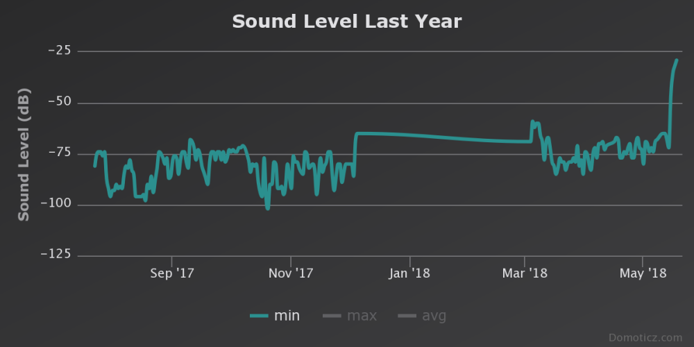
the graph I have gotten from RSSI
It looks like a 'Sound Level' chart, judging from the title...
-
Isn't it better to log the rssi from the nodes? I mean that the gw is sending its rssi every time it receives something, right? So you could have different rssi values for each node.
-
@mfalkvidd said in Soft WDT reset on ESP8266 RFM69 gateway after find parent:
the graph I have gotten from RSSI
It looks like a 'Sound Level' chart, judging from the title...
-
@gohan logging the rssi value on the node would mean additional radio traffic, and I am more interested in how well the node reaches the gateway than how well the gateway reaches the node anyway.
-
@mfalkvidd but how do you know which node rssi is which? You are getting an average of mixed values since domoticz is recording one value every 5 minutes
-
Since my node had been reporting without problems for several days, I disconnected the gateway from my computer and plugged it in to a phone charger instead. The gateway came up as it should and Domoticz reconnected but I am no longer getting any messages from the node. Reset the node but that didn't help. Back to troubleshooting.
-
Alright. I'll add a ceramic capacitor.
For compleeness, here is my complete sketch for the node:
// Enable debug prints
#define MY_DEBUG
#define MY_NODE_ID 1

// Enable and select radio type attached
#define MY_RADIO_RFM69
#define MY_IS_RFM69HW
#define MY_RFM69_FREQUENCY RFM69_433MHZ // RFM69_433MHZ for development branch, RF69_433MHZ for master
#define MY_RF69_IRQ_PIN 2
#define MY_RF69_SPI_CS 10

#include <MySensors.h> // From Library Manager

#include <BME280I2C.h> // From Library Manager
BME280I2C bme;

static const uint64_t UPDATE_INTERVAL = 300000;

#define CHILD_ID_HUM 0
#define CHILD_ID_TEMP 1
#define CHILD_ID_VCC_BEFORE 2
#define CHILD_ID_VCC_AFTER 3

MyMessage msgHum(CHILD_ID_HUM, V_HUM);
MyMessage msgTemp(CHILD_ID_TEMP, V_TEMP);
MyMessage msgVccBefore(CHILD_ID_VCC_BEFORE, V_VOLTAGE);
MyMessage msgVccAfter(CHILD_ID_VCC_AFTER, V_VOLTAGE);
//TODO: Add pressure from BME280?
//TODO: Add light detection (irq-based, LDR)
//TODO: Add flooding detection

void presentation()
{
  // Send the sketch version information to the gateway
  sendSketchInfo("StorageRoom", "1.1");

  present(CHILD_ID_HUM, S_HUM);
  wait(100);
  present(CHILD_ID_TEMP, S_TEMP);
  wait(100);
  present(CHILD_ID_VCC_BEFORE, S_CUSTOM);
  wait(100);
  present(CHILD_ID_VCC_AFTER, S_CUSTOM);
}

void setup()
{
  if (! bme.begin()) {
    Serial.println("Could not find a valid BME280 sensor, check wiring! Continuing without sensor...");
  }
}


void loop()
{
  static float lastTemp;
  static float lastHum;
  send(msgVccBefore.set(readVcc() / 1000.0, 3));
  float temperature = bme.temp();
  if (isnan(temperature)) {
    Serial.println("Failed reading temperature");
  } else if (temperature != lastTemp) {
    // Only send temperature if it changed since the last measurement
    lastTemp = temperature;
    send(msgTemp.set(temperature, 1));
  }
#ifdef MY_DEBUG
  Serial.print("T: ");
  Serial.println(temperature);
#endif

  float humidity = bme.hum();
  if (isnan(humidity)) {
    Serial.println("Failed reading humidity");
  } else if (humidity != lastHum) {
    // Only send humidity if it changed since the last measurement
    lastHum = humidity;
    send(msgHum.set(humidity, 1));
  }
#ifdef MY_DEBUG
  Serial.print("H: ");
  Serial.println(humidity);
#endif

  send(msgVccAfter.set(readVcc() / 1000.0, 3));
  // Sleep for a while to save energy
  sleep(UPDATE_INTERVAL);
}

long readVcc() {
  // From http://provideyourown.com/2012/secret-arduino-voltmeter-measure-battery-voltage/
  // Read 1.1V reference against AVcc
  // set the reference to Vcc and the measurement to the internal 1.1V reference
#if defined(__AVR_ATmega32U4__) || defined(__AVR_ATmega1280__) || defined(__AVR_ATmega2560__)
  ADMUX = _BV(REFS0) | _BV(MUX4) | _BV(MUX3) | _BV(MUX2) | _BV(MUX1);
#elif defined (__AVR_ATtiny24__) || defined(__AVR_ATtiny44__) || defined(__AVR_ATtiny84__)
  ADMUX = _BV(MUX5) | _BV(MUX0);
#elif defined (__AVR_ATtiny25__) || defined(__AVR_ATtiny45__) || defined(__AVR_ATtiny85__)
  ADMUX = _BV(MUX3) | _BV(MUX2);
#else
  ADMUX = _BV(REFS0) | _BV(MUX3) | _BV(MUX2) | _BV(MUX1);
#endif

  delay(2); // Wait for Vref to settle
  ADCSRA |= _BV(ADSC); // Start conversion
  while (bit_is_set(ADCSRA, ADSC)); // measuring

  uint8_t low  = ADCL; // must read ADCL first - it then locks ADCH
  uint8_t high = ADCH; // unlocks both

  long result = (high << 8) | low;

  result = 1125300L / result; // Calculate Vcc (in mV); 1125300 = 1.1*1023*1000
  return result; // Vcc in millivolts
}
and for the gateway:
// Based on https://github.com/mysensors/MySensors/tree/master/examples/GatewayESP8266OTA

#include <ArduinoOTA.h>

// Enable debug prints to serial monitor
#define MY_DEBUG
#define MY_BAUD_RATE 74880 // To be able to see reset messages

#define WIFI_REPORT_INTERVAL 300000

// Enables and select radio type (if attached)
#define MY_RADIO_RFM69
#define MY_IS_RFM69HW
#define MY_RF69_IRQ_PIN D2
#define MY_RF69_IRQ_NUM MY_RF69_IRQ_PIN
#define MY_RF69_SPI_CS D8
#define MY_RFM69_FREQUENCY RFM69_433MHZ // RFM69_433MHZ for development branch, RF69_433MHZ for master

#define MY_GATEWAY_ESP8266

#define MY_WIFI_SSID "Mr-IoT.com"
#include "settings.h"

// Set the hostname for the WiFi Client. This is the hostname
// it will pass to the DHCP server if not static.
#define MY_HOSTNAME "RFM69-Gateway"

// Enable MY_IP_ADDRESS here if you want a static ip address (no DHCP)
//#define MY_IP_ADDRESS 192,168,178,87

// If using static ip you can define Gateway and Subnet address as well
//#define MY_IP_GATEWAY_ADDRESS 192,168,178,1
//#define MY_IP_SUBNET_ADDRESS 255,255,255,0

// The port to keep open on node server mode
#define MY_PORT 5003

// How many clients should be able to connect to this gateway (default 1)
#define MY_GATEWAY_MAX_CLIENTS 2

// Controller ip address. Enables client mode (default is "server" mode).
// Also enable this if MY_USE_UDP is used and you want sensor data sent somewhere.
//#define MY_CONTROLLER_IP_ADDRESS 192, 168, 178, 68

#if defined(MY_USE_UDP)
#include <WiFiUDP.h>
#else
#include <ESP8266WiFi.h>
#endif

#include <MySensors.h>
#define CHILD_ID_WIFI_RSSI 0
MyMessage msgWifiRssi(CHILD_ID_WIFI_RSSI, V_LEVEL);
#define CHILD_ID_RSSI1 1
MyMessage msgRssi1(CHILD_ID_RSSI1, V_LEVEL);
bool sendRssi = false;
int16_t rssi;

void setup()
{
  // Setup locally attached sensors
  ArduinoOTA.onStart([]() {
    DEBUG_OUTPUT("ArduinoOTA start\n");
  });
  ArduinoOTA.onEnd([]() {
    DEBUG_OUTPUT("\nArduinoOTA end\n");
  });
  ArduinoOTA.setPassword((const char *)OTA_PASSWORD);
  ArduinoOTA.setHostname(MY_HOSTNAME);
  ArduinoOTA.onProgress([](unsigned int progress, unsigned int total) {
    DEBUG_OUTPUT("OTA Progress: %u%%\r", (progress / (total / 100)));
  });
  ArduinoOTA.onError([](ota_error_t error) {
    DEBUG_OUTPUT("Error[%u]: ", error);
    if (error == OTA_AUTH_ERROR) {
      DEBUG_OUTPUT("Auth Failed\n");
    } else if (error == OTA_BEGIN_ERROR) {
      DEBUG_OUTPUT("Begin Failed\n");
    } else if (error == OTA_CONNECT_ERROR) {
      DEBUG_OUTPUT("Connect Failed\n");
    } else if (error == OTA_RECEIVE_ERROR) {
      DEBUG_OUTPUT("Receive Failed\n");
    } else if (error == OTA_END_ERROR) {
      DEBUG_OUTPUT("End Failed\n");
    }
  });
  ArduinoOTA.begin();
}

void presentation()
{
  // Present locally attached sensors here
  present(CHILD_ID_WIFI_RSSI, S_SOUND);
  wait(100);
  present(CHILD_ID_RSSI1, S_SOUND);
}

long lastSend = 0;
void loop()
{
  // Send locally attech sensors data here
  ArduinoOTA.handle();
  if (millis() - lastSend > WIFI_REPORT_INTERVAL) {
    send(msgWifiRssi.set(WiFi.RSSI(), 1));
    lastSend = millis();
  }
  if (sendRssi) {
    sendRssi = false;
    send(msgRssi1.set(rssi, 0));
  }
}

void receive(const MyMessage &message)
{
  rssi = _radio.RSSI;
  if (message.sender == 1) {
    sendRssi = true;
  }
}
Hello! It looks like you're interested in this conversation, but you don't have an account yet.
Getting fed up of having to scroll through the same posts each visit? When you register for an account, you'll always come back to exactly where you were before, and choose to be notified of new replies (either via email, or push notification). You'll also be able to save bookmarks and upvote posts to show your appreciation to other community members.
With your input, this post could be even better 💗
Register Login