Using loop function with MySensors-master/examples/ (2.2)
-
Thanks for your answer,
here the thing:
i've 4 relays connected to an Adruino nano(328)
MysensorSerialGatreway is doing the right job and all is working.
But, i want to add a timeout option that switch off a relay after timeout reached.
I want this option in case of a freeze or bug with my domoticz controller (running on a raspberry pi)
Relay are used for watering my garden, so i prefer having a solution on my arduino for switching off relays in case of any bug.So, my idea is pretty simple:
each time a relay is switched on i store the time
(i'm doing this in receive() function)In the loop function i do some tests and check the timeout for each relayI wanted to know if it was working (i do think my code is correct) so i put some Serial output.
as you can see in setup() or in loop(), there are two outputs.
I do have the Mysensors classic outputs but mine do not produce anything.
so have you an idea ?
thanks a lot.
here my code:
/**
- The MySensors Arduino library handles the wireless radio link and protocol
- between your home built sensors/actuators and HA controller of choice.
- The sensors forms a self healing radio network with optional repeaters. Each
- repeater and gateway builds a routing tables in EEPROM which keeps track of the
- network topology allowing messages to be routed to nodes.
- Created by Henrik Ekblad henrik.ekblad@mysensors.org
- Copyright (C) 2013-2015 Sensnology AB
- Full contributor list: https://github.com/mysensors/Arduino/graphs/contributors
- Documentation: http://www.mysensors.org
- Support Forum: http://forum.mysensors.org
- This program is free software; you can redistribute it and/or
- modify it under the terms of the GNU General Public License
- version 2 as published by the Free Software Foundation.
- REVISION HISTORY
- Version 1.0 - Henrik Ekblad
- DESCRIPTION
- Example sketch showing how to control physical relays.
- This example will remember relay state after power failure.
- http://www.mysensors.org/build/relay
*/
// Enable debug prints to serial monitor
#define MY_DEBUG// Enable and select radio type attached
#define MY_RADIO_NRF24
//#define MY_RADIO_NRF5_ESB
//#define MY_RADIO_RFM69
//#define MY_RADIO_RFM95// Enable repeater functionality for this node
#define MY_REPEATER_FEATURE#include <MySensors.h>
#define RELAY_PIN 4 // Arduino Digital I/O pin number for first relay (second on pin+1 etc)
#define NUMBER_OF_RELAYS 4 // Total number of attached relays
#define RELAY_ON 1 // GPIO value to write to turn on attached relay
#define RELAY_OFF 0 // GPIO value to write to turn off attached relayunsigned long t1[4]; // Calcul de la durée depuis l'activation d'un relay
#define DUREEMAX 3600000 // duréee maximale après laquelle les relais sont automatiquement éteintsvoid before()
{
for (int sensor=1, pin=RELAY_PIN; sensor<=NUMBER_OF_RELAYS; sensor++, pin++) {
// Then set relay pins in output mode
pinMode(pin, OUTPUT);
// Set relay to last known state (using eeprom storage)
digitalWrite(pin, loadState(sensor)?RELAY_ON:RELAY_OFF);
}
}
void setup()
{
Serial.begin(115200);
Serial.println("setup ok");
}void presentation()
{
// Send the sketch version information to the gateway and Controller
sendSketchInfo("Relay", "1.0");for (int sensor=1, pin=RELAY_PIN; sensor<=NUMBER_OF_RELAYS; sensor++, pin++) { // Register all sensors to gw (they will be created as child devices) present(sensor, S_BINARY); }}
void loop() //my watchdog
{
unsigned long t=millis();
unsigned long t2[4];if (t>=t1[0]) {t2[0]=t-t1[0];} // if t<t1 then millis() function have reached the max value on a arduino (after 50 working day ), and get back to 0
else
{t2[0]=4294967295-t1[0]+t; }if (t>=t1[1]) {t2[1]=t-t1[1];}
else
{t2[1]=4294967295-t1[1]+t; }if (t>=t1[2]) {t2[2]=t-t1[2];}
else
{t2[2]=4294967295-t1[2]+t; }if (t>=t1[3]) {t2[3]=t-t1[3];}
else
{t2[3]=4294967295-t1[3]+t; }if (t2[0]>DUREEMAX) { digitalWrite(RELAY_PIN,RELAY_OFF);} // switch off relay, timeout reached
if (t2[1]>DUREEMAX) { digitalWrite(RELAY_PIN+1,RELAY_OFF);} // switch off relay, timeout reached
if (t2[2]>DUREEMAX) { digitalWrite(RELAY_PIN+2,RELAY_OFF);} // switch off relay, timeout reached
if (t2[3]>DUREEMAX) { digitalWrite(RELAY_PIN+3,RELAY_OFF);} // switch off relay, timeout reachedSerial.println("loop test");
}
void receive(const MyMessage &message)
{
// We only expect one type of message from controller. But we better check anyway.
if (message.type==V_STATUS) {
// Change relay state
digitalWrite(message.sensor-1+RELAY_PIN, message.getBool()?RELAY_ON:RELAY_OFF);
// Store state in eeprom
saveState(message.sensor, message.getBool());
// Write some debug info
Serial.print("Incoming change for sensor:");
Serial.print(message.sensor);
Serial.print(", New status: ");
Serial.println(message.getBool());
if (message.sensor-1<4 && message.sensor-1>=0)
{t1[message.sensor-1] = millis();}}}
-
here a snapshot of the Serial output (is that you wanted ?)
One more thing
usually, when I compile sketch without loop() or setup() function, an error is done.
But here, i can remove loop() and setup() function and compile without any errorscan both functions (loop and setup) be located elsewhere ? in a .h ou .cpp dependencies that used with #include Mysensors.h
One last thing,
I use last version of IDE Arduino , under debian computer.
When i compile other sketch (my very firsts examples, without Mysensors) loop() and setup() have the right behaviorthank for help,
Eric.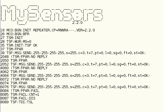
-
Hi,
One more thing: even if compilation succeed, there are always two warnings:

Warnings are (my traduction):
WARNING : wrong .ci folder in library "Mysensors"
WARNINR : wrong .mystools floder in library "Mysensors"
For any sketch (using or not Mysensors) i do have this Warning, since i've installed mysensors library.It might be the the problem ?
thank,
Eric. -
here a snapshot of the Serial output (is that you wanted ?)
One more thing
usually, when I compile sketch without loop() or setup() function, an error is done.
But here, i can remove loop() and setup() function and compile without any errorscan both functions (loop and setup) be located elsewhere ? in a .h ou .cpp dependencies that used with #include Mysensors.h
One last thing,
I use last version of IDE Arduino , under debian computer.
When i compile other sketch (my very firsts examples, without Mysensors) loop() and setup() have the right behaviorthank for help,
Eric.@eric007 the debug output shows that the node is unable to find a path to the gateway. The default setting is to not enter setup or loop until communication has been established (since, for most use cases, running a node without communication isn't very useful)
What type of gateway are you using? Could you post the debug output from it?
-
Hi,
One more thing: even if compilation succeed, there are always two warnings:
Warnings are (my traduction):
WARNING : wrong .ci folder in library "Mysensors"
WARNINR : wrong .mystools floder in library "Mysensors"
For any sketch (using or not Mysensors) i do have this Warning, since i've installed mysensors library.It might be the the problem ?
thank,
Eric. -
Hi,
it works perfectly, you were so right from the beginning.
I took a wrong way because of the compilation success without loop() and setup() function in my sketch.
Anyway, my project works fine and thank you again.
Hello! It looks like you're interested in this conversation, but you don't have an account yet.
Getting fed up of having to scroll through the same posts each visit? When you register for an account, you'll always come back to exactly where you were before, and choose to be notified of new replies (either via email, or push notification). You'll also be able to save bookmarks and upvote posts to show your appreciation to other community members.
With your input, this post could be even better 💗
Register Login