Sensor to control remote controlled switches from Flamingo.eu e.g. mumbi m-FS300
-
Some days ago I bought some mumbi switches. The switches have to be teached using the remote control during the first few seconds after power on. So there are no DIP switches nor any other predefined codes I can use. But the switches are cheap and that was the reason I wantet have them in my homeautomation.
The mission was to find out the protocol as well as the codes the remote control is sending to its switches. Then I wanted to turn on/off the switches using my homeautomation controller (fhem). To expand the range I wanted to have a mysensors device which can be placed everywhere around my house:
I will add some more details and photos the upcomming days. But to cut it short: I uploaded the library together with a mysensors sketch to:
https://github.com/windkh/flamingoswitch.gitThe device has 5 child sensors:
Sensor 0 is used to sniff for codes on the air. It can also be used to send codes directly to the air.
Sensor 1-4 are used with sniffed codes from my remote control. You will have to replace the codes in the sketch with the ones your remote control is sending.The receiver and sender hardware can be bought anywhere on the net like e.g.: http://www.amazon.de/Empfänger-Superregeneration-Raspberry-Wireless-Transmitter-433-MHz-Funk-Sende-Modul-für-Arduino/dp/B00M0XTP4W
... to be continued
-
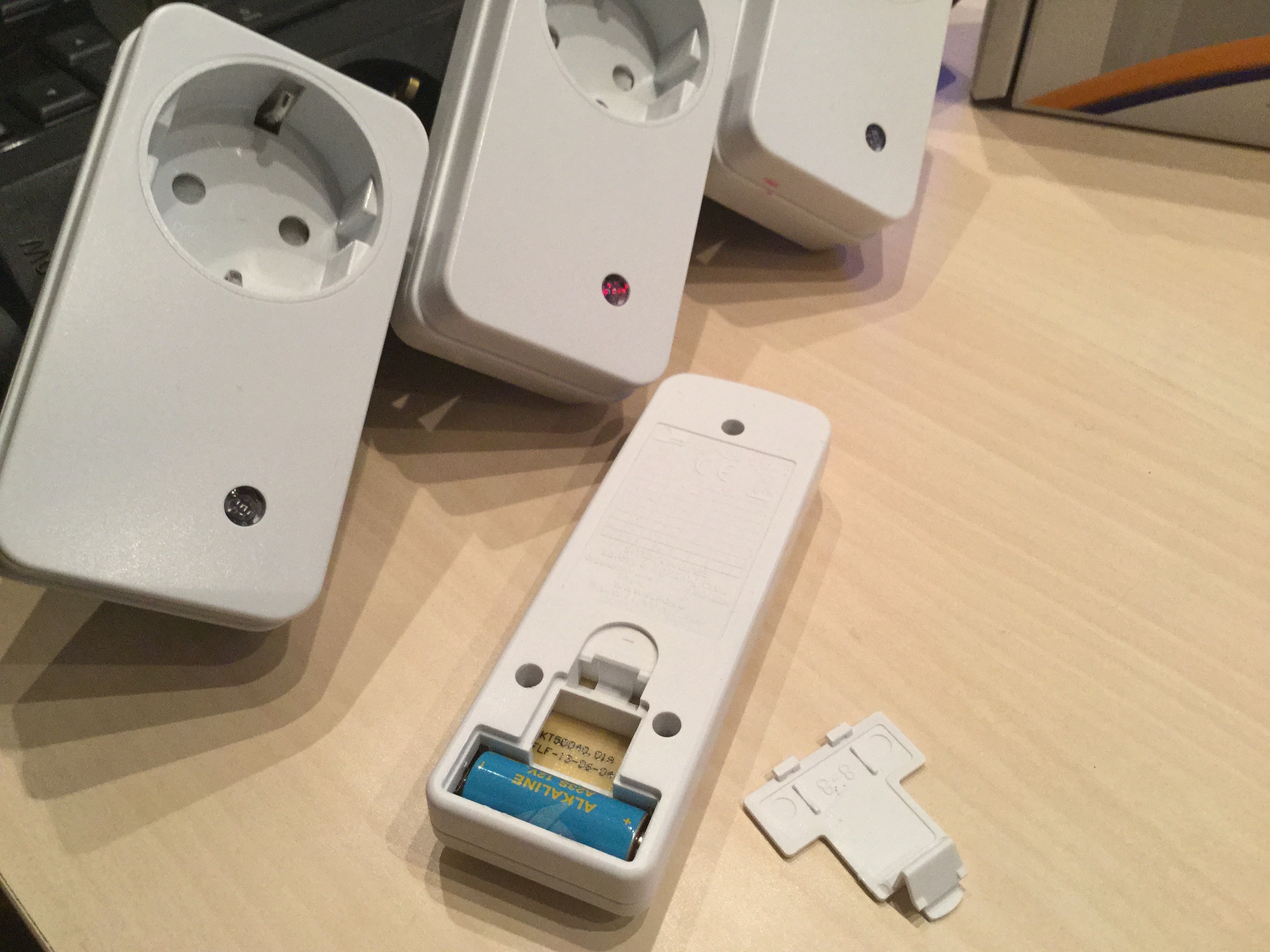
This is a picture of the outlets and the remote control. You can see that the remote control does not have any DIP switches anymore:
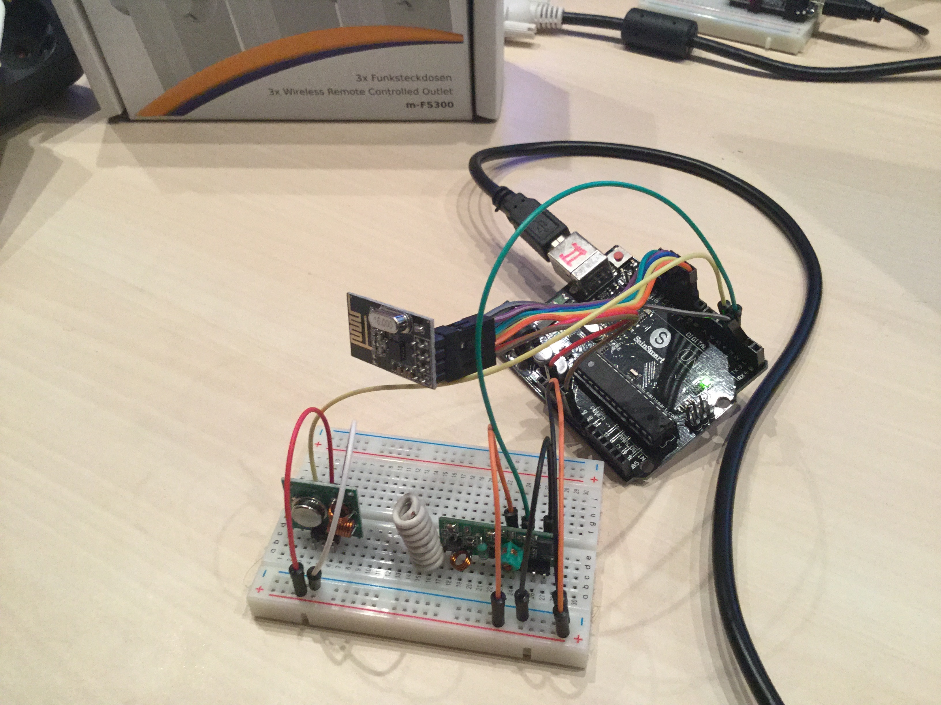
The hardware setup is straight forward: the sender on the left is connected to PIN 4 and the receiver on the right is connected to PIN 3 of the arduino:
I analyzed the codes of the remote control using the "poor-man's oszilliscope" and audacitiy. Further details can be found here:
http://forum.arduino.cc/index.php?topic=201771.0Finally I developed a library that is very similar to the rcswitch one to be able to read the codes from the remote-control.
The sketch contains receiver and sender functionality at the same time to make experimenting easier. In future there will be at least one sender sensor and one receiver in my sensor network. The receiver will be probably in my living room while the sender node will be at the other end of my mysensors network. The codes of the remotecontrol will be routed through the 2.4GHz network to the 433Mhz sender.0. Initialisation:
FlamingoSwitch Switch;
Switch.enableReceive(IRQ_PIN);
Switch.enableTransmit(TX_PIN);
1. Receiving codes from the remote control:
if (Switch.available())
{
    unsigned long code = Switch.getReceivedValue();
    uint32_t state = code << 4; // 28Bit --> 32Bit
    Serial.print("Detected code:");
    Serial.print(state, HEX);
    Serial.println("");
    Switch.resetAvailable();
}
As the code is 28Bit long the rest of the 32Bit number is filled up with 0.
2. Sending codes to the outlets:
Switch.send(code);The sketch demonstrates two different possibilities of how to use the library.
1. Controller stores codes of outlets:
The sketch registers sensor 0 as custom device: gw.present(0, S_CUSTOM);
This sensor 0 is used to sniff for codes received from the remote control. It will send the detected code to the mysensors network controller. The controller can send these codes back to sensor 0 to switch the outlets. In this mode the controller needs to store the codes for the different outlets in its configuration.2. Codes are stored in sketch:
The sketch registers sensor 1-4 as light sensor: gw.present(sensorId, S_LIGHT);
The sensor can be switched on/off from the controller. As the remote control sends 4 different codes for each button I included all of them in the sample sketch though only one of the four codes is neccessary to control the outlet..... to be continued
-
Integration into FHEM:
The integration of the sensor in FHEM is easy:
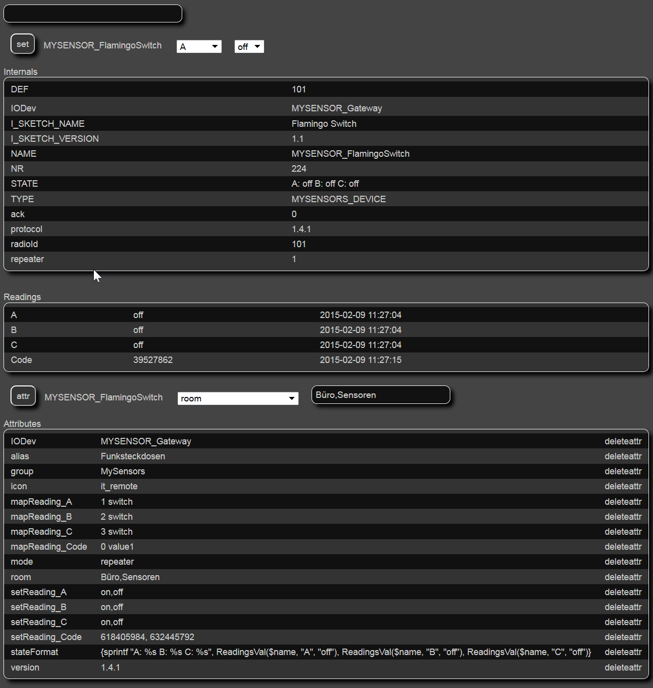
You can see the Readings for the sniffer called "Code" and the outlets A, B, C with their state (all turned off). You can control
the outlets using the combo-boxes and the set button on the top. If you press a button on the remote control the code is displayed in the "Code" Reading. The user may write it down for later usage. If FHEM writes a code to this variable then the value is transmitted back to the sensor 0 and thus on the 433Mhz radio.The FHEM code looks like:
define MYSENSOR_FlamingoSwitch MYSENSORS_DEVICE 101
attr MYSENSOR_FlamingoSwitch IODev MYSENSOR_Gateway
attr MYSENSOR_FlamingoSwitch alias Funksteckdosen
attr MYSENSOR_FlamingoSwitch group MySensors
attr MYSENSOR_FlamingoSwitch icon it_remote
attr MYSENSOR_FlamingoSwitch mapReading_Code 0 value1
attr MYSENSOR_FlamingoSwitch mapReading_A 1 switch
attr MYSENSOR_FlamingoSwitch mapReading_B 2 switch
attr MYSENSOR_FlamingoSwitch mapReading_C 3 switch
attr MYSENSOR_FlamingoSwitch mode repeater
attr MYSENSOR_FlamingoSwitch room Büro,Sensoren
attr MYSENSOR_FlamingoSwitch setReading_Code 618405984, 632445792
attr MYSENSOR_FlamingoSwitch setReading_A on,off
attr MYSENSOR_FlamingoSwitch setReading_B on,off
attr MYSENSOR_FlamingoSwitch setReading_C on,off
attr MYSENSOR_FlamingoSwitch stateFormat {sprintf "A: %s B: %s C: %s", ReadingsVal($name, "A", "off"), ReadingsVal($name, "B", "off"),     ReadingsVal($name, "C", "off")}
attr MYSENSOR_FlamingoSwitch version 1.4.1
You can see that A, B, C do not need any codes in this configuration while the setReading_Code instruction has two. This demonstrates the two different possibilities of where to store the codes (on the controller or on the sensor node).
The next picture shows the visualisation of the outlets A, B, C and the "Code" outlet:
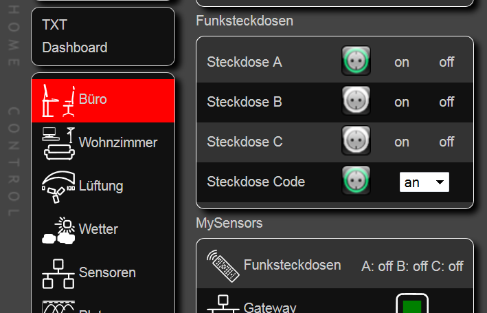
The FHEM code for A looks like:
define MYSENSOR_FlamingoSwitch_A dummy
attr MYSENSOR_FlamingoSwitch_A alias Steckdose A
attr MYSENSOR_FlamingoSwitch_A devStateIcon off:black_Steckdose.off on:black_Steckdose.on
attr MYSENSOR_FlamingoSwitch_A group Funksteckdosen
attr MYSENSOR_FlamingoSwitch_A room Büro
attr MYSENSOR_FlamingoSwitch_A setList on off
attr MYSENSOR_FlamingoSwitch_A webCmd on:off
define MYSENSOR_FlamingoSwitch_A_Notify notify MYSENSOR_FlamingoSwitch_A set MYSENSOR_FlamingoSwitch A %
define MYSENSOR_FlamingoSwitch_A_Notify2 notify MYSENSOR_FlamingoSwitch:A set MYSENSOR_FlamingoSwitch_A %
while the code for the "Code" outlet looks like:
define MYSENSOR_FlamingoSwitch_Code dummy
attr MYSENSOR_FlamingoSwitch_Code alias Steckdose Code
attr MYSENSOR_FlamingoSwitch_Code devStateIcon 618405984:black_Steckdose.off 632445792:black_Steckdose.on
attr MYSENSOR_FlamingoSwitch_Code eventMap aus:618405984 an:632445792
attr MYSENSOR_FlamingoSwitch_Code group Funksteckdosen
attr MYSENSOR_FlamingoSwitch_Code room Büro
attr MYSENSOR_FlamingoSwitch_Code setList state:aus,an
attr MYSENSOR_FlamingoSwitch_Code webCmd state
define MYSENSOR_FlamingoSwitch_Code_Notify notify MYSENSOR_FlamingoSwitch_Code set MYSENSOR_FlamingoSwitch Code %
best regards windkh
-
@Heinz nice project !!!
I use VERA, I did a My Relay Module, if I push button or send command on vera, i have alwais a state of socket.
with your system, you can know the status of the socket?
from the photo, I dont' see a button to turn on the socket !!!! Only via remote control!!!
gigi
-
@gigi
in FHEM you can turn the socket on/off by tapping on the "on"/"off" label. As long as you control your sockets via FHEM you know the state of the socket. But if you use your remote control, too you get out of sync as there is no chance to get the actual state from those type of sockets. -
I would like to adapt your sketch to control my Rf (433MHz) plugin switches, which do have a DIP switch (I think it should be easier ?) and also include temperature reading for two Dallas sensors. The goal is to monitor my heating system and turn on/off the recirculating pumps using the 433MHz switches. Up until now this has been done manually (through remote), but I would really love to automate this.
The problem is that I suck badly at coding, everything goes over my head (sorry), so I would appreciate any help with this, and hopefully help others in the process.
I've included below pictures with the remote and switch I have, so we know the chip (HX2262) it uses :
Remote
SwitchI would really appreciate any help you guys can give me.
LE: I'll start my own thread for this, as I was able to identify the codes using the RC Switch library.Thank you.
-
Hi @CaptainZap
I think that the flamingo switch lib does not support your remote switches. But you could try to take my sketch and replace the FlamingoSwitch lib with the rcswitch lib. It has the same function calls, but supports 3 other protocols.
Unfortunately I don't have enough time to write the sketch for you. -
Hi @CaptainZap
I think that the flamingo switch lib does not support your remote switches. But you could try to take my sketch and replace the FlamingoSwitch lib with the rcswitch lib. It has the same function calls, but supports 3 other protocols.
Unfortunately I don't have enough time to write the sketch for you.@Heinz No need to write the code for me, I've done most of the work already but the only problems I have now is that with the sketch from this thread I can't control the 3 switches I have and the two temperature sensors are not detected by the Vera interface (I guess they aren't initialized correctly ?).
I would appreciate if you could take a look at it.
Hello! It looks like you're interested in this conversation, but you don't have an account yet.
Getting fed up of having to scroll through the same posts each visit? When you register for an account, you'll always come back to exactly where you were before, and choose to be notified of new replies (either via email, or push notification). You'll also be able to save bookmarks and upvote posts to show your appreciation to other community members.
With your input, this post could be even better 💗
Register Login