💬 EFEKTA Temp&Hum sensor(ver. nRF52 )+E-Ink display
-
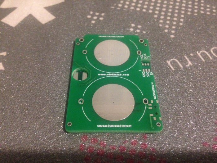
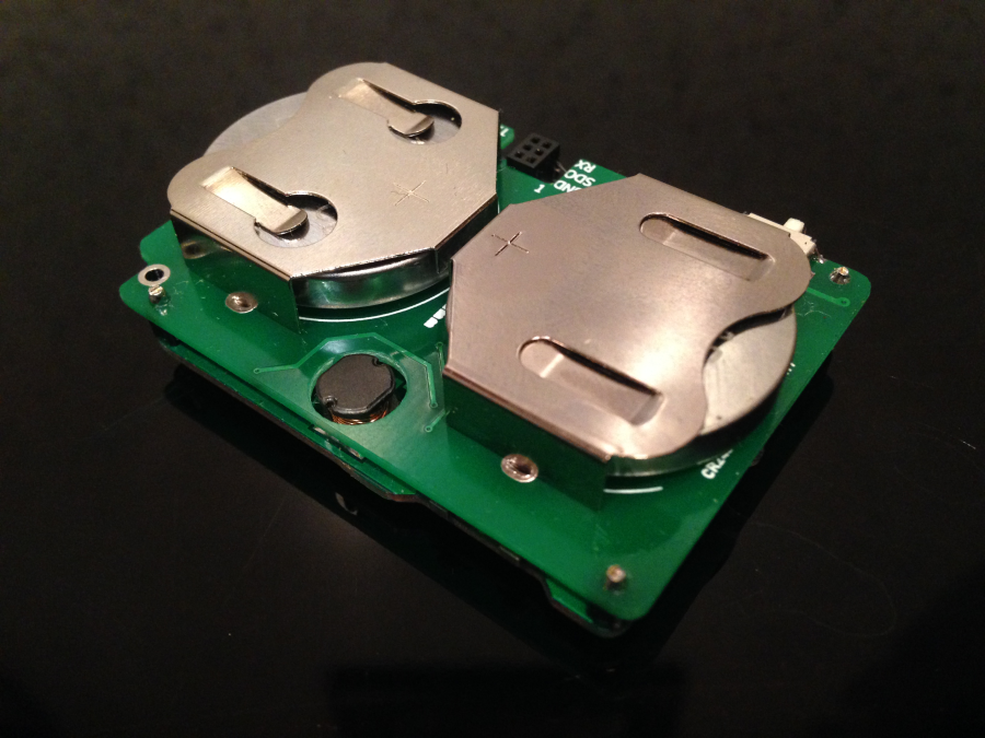
The second revision of the device is ready, the tests are passed. Added cutouts and holes on the power Board for mounting in the case. Transferred inductance of the display (680), made a cut for her on the power PCB. All this slightly reduced the size of the device, now the size of 36mm x 52mm (old size 36mm x 54mm). The down-converter moves to the other side of the power PCB.
-
@berkseo good to hear. And you also mentioned to send some new PCB'
s? Let me know if I had to pay something additional. -
@berkseo looks very good, very professional work. I'll solder a few devices once I get the new PCB's and will also work further on my version of the firmware. It works already quite nice (transfering float values and showing decimals).
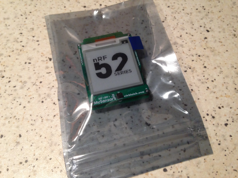
Attached the picture of a working pair of a sensor node (using my PCB's) and a SHT31 and a nRF52 serial gateway.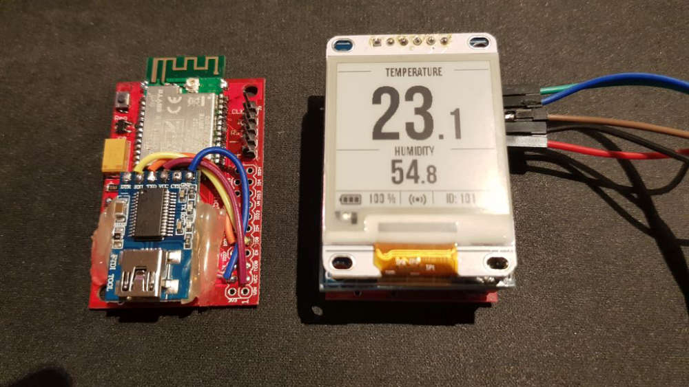
-
@berkseo I've got your Temp/Hum sensor today and the PCB's (3+3). Since I have ordered the cr2477 batteries and your batterholder takes only the cr2450, I've tried it with the program adapter and USB power. It works. Thanks. I have ordered now additional cr2450 batteries.
I took the batteryholder form your list and they are for the cr2477!Then I soldered my own first two PCB's, the battery PCB and the Sensor PCB. It took me quite a while (3 hours at least). It's nothing for beginners (but I not a beginner :-) )
However during my testing, I found my battery PCB working and the sensor node runs the MYSensors part and the LED blinks but the E-Paper does not work and also the SHT20 returns 998 for temp and hum.I have not found the C12 capacitor in your parts decription list, but only a C14 (which is not printed on the PCB) with 10uF. So I assumed the C12 = 10uF. I have seached the page and there is no C12.
One the other hand, I have not found C14 on the new PCB. Maybe it's below C13 and no part print on PCB? The C13 is larger then the pads below, so it's confusing.
Maybe you can update/correct it on openhwardware, so that I can solder it correct.So looking for the problems with e-paper and SHT20: A schematic diagram would really really help me, otherwise I'm lost. Please provide it (or at least via a PM?).
Would it be possible to get it? If you have e.g. an Eagle project (schematics and board).It was really essential, that you provided the programm adapter for the tiny SWD connector. Thanks for that!
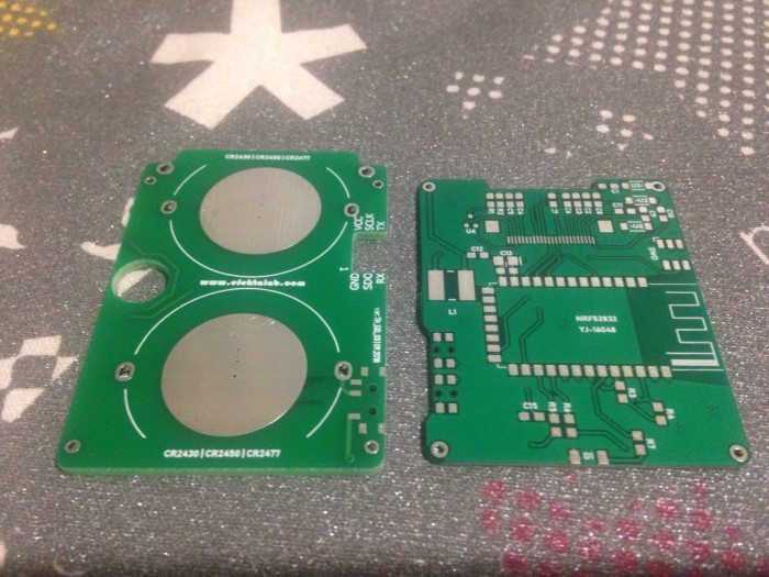
here are my soldered PCB's:
-
@berkseo I've got your Temp/Hum sensor today and the PCB's (3+3). Since I have ordered the cr2477 batteries and your batterholder takes only the cr2450, I've tried it with the program adapter and USB power. It works. Thanks. I have ordered now additional cr2450 batteries.
I took the batteryholder form your list and they are for the cr2477!Then I soldered my own first two PCB's, the battery PCB and the Sensor PCB. It took me quite a while (3 hours at least). It's nothing for beginners (but I not a beginner :-) )
However during my testing, I found my battery PCB working and the sensor node runs the MYSensors part and the LED blinks but the E-Paper does not work and also the SHT20 returns 998 for temp and hum.I have not found the C12 capacitor in your parts decription list, but only a C14 (which is not printed on the PCB) with 10uF. So I assumed the C12 = 10uF. I have seached the page and there is no C12.
One the other hand, I have not found C14 on the new PCB. Maybe it's below C13 and no part print on PCB? The C13 is larger then the pads below, so it's confusing.
Maybe you can update/correct it on openhwardware, so that I can solder it correct.So looking for the problems with e-paper and SHT20: A schematic diagram would really really help me, otherwise I'm lost. Please provide it (or at least via a PM?).
Would it be possible to get it? If you have e.g. an Eagle project (schematics and board).It was really essential, that you provided the programm adapter for the tiny SWD connector. Thanks for that!
here are my soldered PCB's:
@heinzv said in 💬 EFEKTA Temp&Hum sensor(ver. nRF52832 )+E-Ink display:
I've got your Temp/Hum sensor today and the PCB's (3+3). Since I have ordered the cr2477 batteries and your batterholder takes only the cr2450, I've tried it with the program adapter and USB power. It works. Thanks. I have ordered now additional cr2450 batteries.
I took the batteryholder form your list and they are for the cr2477!
Then I soldered my own first two PCB's, the battery PCB and the Sensor PCB. It took me quite a while (3 hours at least). It's nothing for beginners (but I not a beginner )
However during my testing, I found my battery PCB working and the sensor node runs the MYSensors part and the LED blinks but the E-Paper does not work and also the SHT20 returns 998 for temp and hum.
I have not found the C12 capacitor in your parts decription list, but only a C14 (which is not printed on the PCB) with 10uF. So I assumed the C12 = 10uF. I have seached the page and there is no C12. All capacitors are ceramic.
One the other hand, I have not found C14 on the new PCB. Maybe it's below C13 and no part print on PCB? The C13 is larger then the pads below, so it's confusing.
Maybe you can update/correct it on openhwardware, so that I can solder it correct.
So looking for the problems with e-paper and SHT20: A schematic diagram would really really help me, otherwise I'm lost. Please provide it (or at least via a PM?).
Would it be possible to get it? If you have e.g. an Eagle project (schematics and board).
It was really essential, that you provided the programm adapter for the tiny SWD connector. Thanks for that!
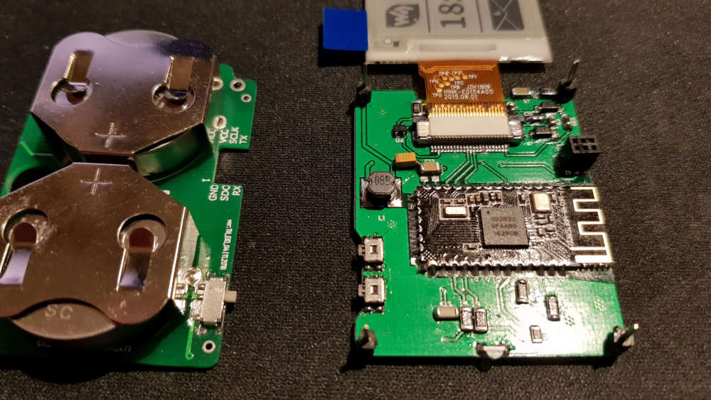
here are my soldered PCB's:There are 3 types of battery holders, I make ready-made devices only on 2450, it is optimal, 2477 very high, the device in the case turns out to be disproportionate.
I solder for about half an hour:). Judging by the description of your problems, it's all about soldering. Solder the temperature sensor and the connector for the display should be a Hairdryer and solder paste. This is by the way perhaps the two most difficult procedures at home.
C13 is a capacitor from 47mf to 200mf, I added it later. C14 is a 0.1 mf capacitor. C12 is a capacitor on the display inductance input, it should be from 4.7 mf to 10mf.
Full schemes there is no, there is only parts of. I have this project done right in the program for PCB layout. But I understand that this is becoming a problem, and I will add the scheme to the project in the near future. Sorry, I know I should have done this a long time ago :((.
You wrote a post last year :), I with the holidays just gave all that up. How you're doing now. Were you able to find a problem with the display and the temperature sensor?
-
@heinzv said in 💬 EFEKTA Temp&Hum sensor(ver. nRF52832 )+E-Ink display:
I've got your Temp/Hum sensor today and the PCB's (3+3). Since I have ordered the cr2477 batteries and your batterholder takes only the cr2450, I've tried it with the program adapter and USB power. It works. Thanks. I have ordered now additional cr2450 batteries.
I took the batteryholder form your list and they are for the cr2477!
Then I soldered my own first two PCB's, the battery PCB and the Sensor PCB. It took me quite a while (3 hours at least). It's nothing for beginners (but I not a beginner )
However during my testing, I found my battery PCB working and the sensor node runs the MYSensors part and the LED blinks but the E-Paper does not work and also the SHT20 returns 998 for temp and hum.
I have not found the C12 capacitor in your parts decription list, but only a C14 (which is not printed on the PCB) with 10uF. So I assumed the C12 = 10uF. I have seached the page and there is no C12. All capacitors are ceramic.
One the other hand, I have not found C14 on the new PCB. Maybe it's below C13 and no part print on PCB? The C13 is larger then the pads below, so it's confusing.
Maybe you can update/correct it on openhwardware, so that I can solder it correct.
So looking for the problems with e-paper and SHT20: A schematic diagram would really really help me, otherwise I'm lost. Please provide it (or at least via a PM?).
Would it be possible to get it? If you have e.g. an Eagle project (schematics and board).
It was really essential, that you provided the programm adapter for the tiny SWD connector. Thanks for that!
here are my soldered PCB's:There are 3 types of battery holders, I make ready-made devices only on 2450, it is optimal, 2477 very high, the device in the case turns out to be disproportionate.
I solder for about half an hour:). Judging by the description of your problems, it's all about soldering. Solder the temperature sensor and the connector for the display should be a Hairdryer and solder paste. This is by the way perhaps the two most difficult procedures at home.
C13 is a capacitor from 47mf to 200mf, I added it later. C14 is a 0.1 mf capacitor. C12 is a capacitor on the display inductance input, it should be from 4.7 mf to 10mf.
Full schemes there is no, there is only parts of. I have this project done right in the program for PCB layout. But I understand that this is becoming a problem, and I will add the scheme to the project in the near future. Sorry, I know I should have done this a long time ago :((.
You wrote a post last year :), I with the holidays just gave all that up. How you're doing now. Were you able to find a problem with the display and the temperature sensor?
@berkseo Happy new year! I was waiting for an answer from you, so I have not done any further investigation before I have more infos ;-)
I have now ordered another batch of 2450 battery holders (I have obviously clicket in the second link in your parts list which was the 2477).So based on your info, my C13 is definitly wrong, I have used a 0.1uF and need to change it to a 100uf (what are you using as you write 47uF to 200uF ?). I think I need to order them first. For C12 I used a 10uF so that fits.
I think I could also have some problems with the 0.1uF parts as I have only the larger 1206 which I have to replace with 805 or 603 sized. I have ordered them already but you know that takes another 4-6weeks. So I'll wait till all parts are there and continue then with your infos and the correct ordered parts.
I have also problems with my new script as my power consumption was first 0.8mA (800uA) and now it's even 3.1mA during sleep (on my other PCB's), but was following your sleep procedure (putting all internal and external devices to powerdown). I was expecting somewhat between 2 and 20uA, so I have to analyze what is wrong.
So you solder your PCB in 0.5hour? Then I might order the PCB's bette rfrom you :-) It takes me at least 2+ hours (the first was 3hrs).
I have a super small soldering iron and I also have a hot air SMD soldering station and quality solder paste. May I try it again with solder paste.more then later.
thanks and bye till later
Heinz -
"L1, Inductance 4.7uh 1210 1 pcs", the text says 4.7uh but link goes to a store that sells 47uh. Which should it be?
-
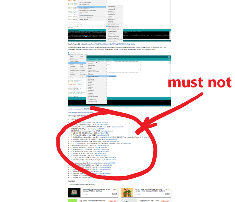
The project became closed. Reason: I previously placed links to all the necessary components for this device(see screenshot). This allowed me to earn quite a bit on the affiliate program. This allowed me a bit to recoup the costs, they are not small. The site administration considers this type of earnings unacceptable.
-
The project became closed. Reason: I previously placed links to all the necessary components for this device(see screenshot). This allowed me to earn quite a bit on the affiliate program. This allowed me a bit to recoup the costs, they are not small. The site administration considers this type of earnings unacceptable.
@berkseo Seriously!!!!!!!!!!!!! It cannot be true!!! I have just ordered PCBs and all needed stuff to assemble it, and now the code is gone!!! Please post the code again, or make it available on alternative sites.. please. It is hundreds of dollars to waste otherwise!
-
@berkseo Seriously!!!!!!!!!!!!! It cannot be true!!! I have just ordered PCBs and all needed stuff to assemble it, and now the code is gone!!! Please post the code again, or make it available on alternative sites.. please. It is hundreds of dollars to waste otherwise!
@magpern said in 💬 EFEKTA Temp&Hum sensor(ver. nRF52832 )+E-Ink display:
Seriously!!!!!!!!!!!!! It cannot be true!!! I have just ordered PCBs and all needed stuff to assemble it, and now the code is gone!!! Please post the code again, or make it available on alternative sites.. please. It is hundreds of dollars to waste otherwise!
The project will remain open, like others. I was in a bad mood that day:)... The rules of the site administration are reasonable, and the decision to open the project was mine.
Code for Arduino IDE - https://drive.google.com/file/d/13wmxCt9XehJr1E2eyG1RnYsQTMb9A2LR/view?usp=sharing
-
development continues...
-
@berkseo said in 💬 EFEKTA Temp&Hum sensor(ver. nRF52832 )+E-Ink display:
@magpern said in 💬 EFEKTA Temp&Hum sensor(ver. nRF52832 )+E-Ink display:
Seriously!!!!!!!!!!!!! It cannot be true!!! I have just ordered PCBs and all needed stuff to assemble it, and now the code is gone!!! Please post the code again, or make it available on alternative sites.. please. It is hundreds of dollars to waste otherwise!
The project will remain open, like others. I was in a bad mood that day:)... The rules of the site administration are reasonable, and the decision to open the project was mine.
Code for Arduino IDE - https://drive.google.com/file/d/13wmxCt9XehJr1E2eyG1RnYsQTMb9A2LR/view?usp=sharing
Thank you! You scared me big time!
Bad ting without links is that eg. clock button 2 pcs... there are millions of clock buttons and to pick the right one with out a link.. well, almost impossible.Thanks again!
-
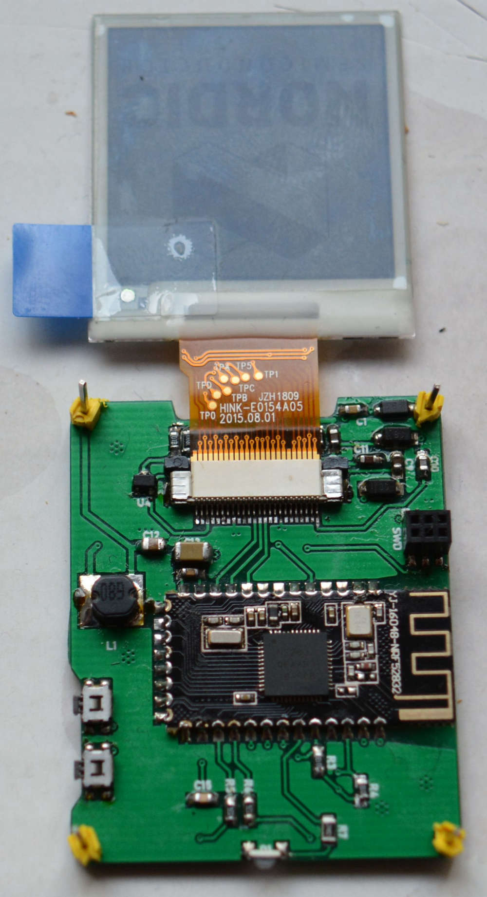
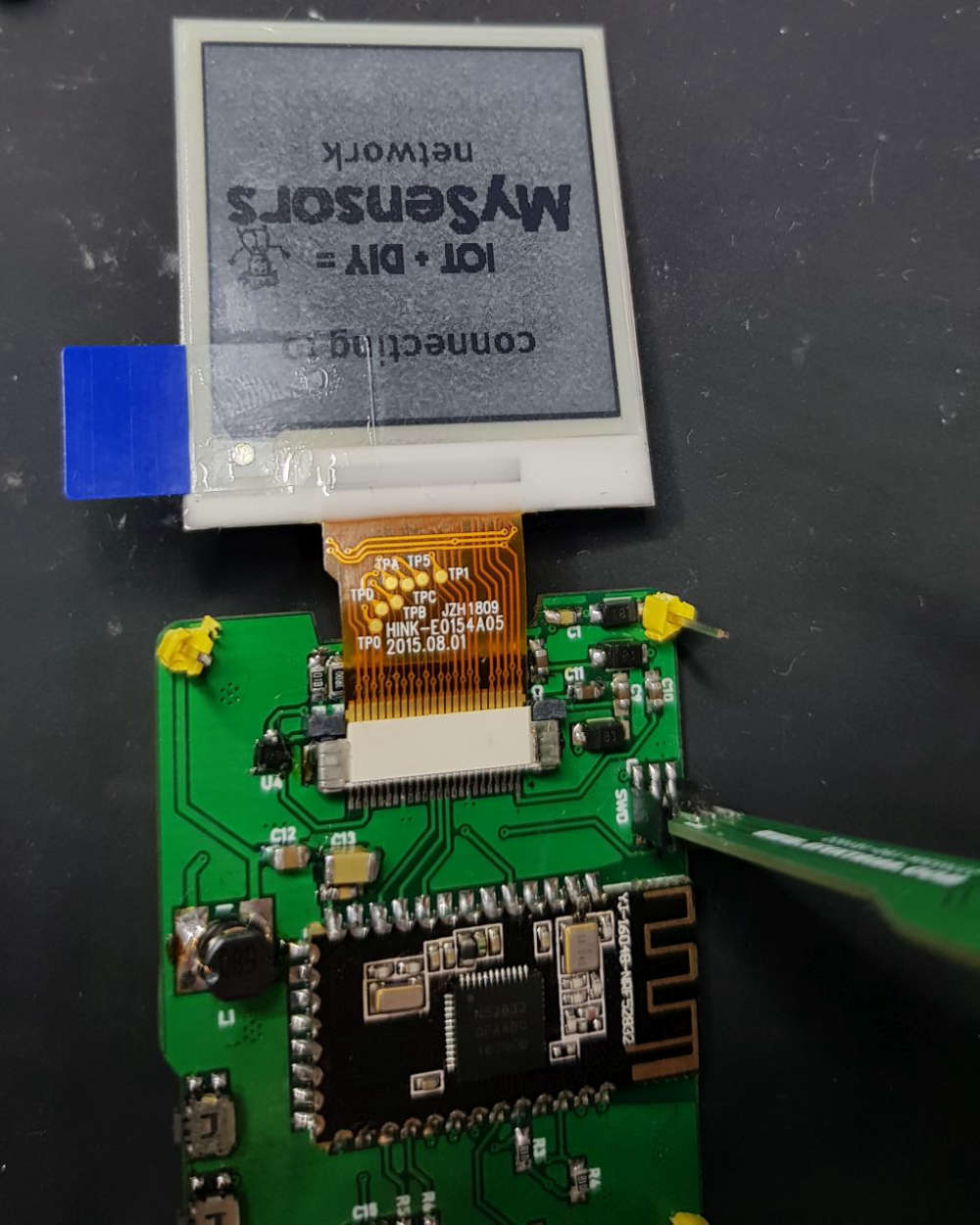
@berkseo I have continued to work on the new PCB's und have oredered some 603 resistors und condensors. I have checked all of the parts and the soldering but did not get the one PCB to displays something. The program runs und I see the LED flashing and also the log looks normal.
A build a second PCB and this one shows the intro graphics but with a grey background and then it stops showing something. No idea what goes wrong.
-
@berkseo I have continued to work on the new PCB's und have oredered some 603 resistors und condensors. I have checked all of the parts and the soldering but did not get the one PCB to displays something. The program runs und I see the LED flashing and also the log looks normal.
A build a second PCB and this one shows the intro graphics but with a grey background and then it stops showing something. No idea what goes wrong.
@heinzv
I apologize that long did not answer. Did you solve the problem? I noticed that the inductance is small (it seemed to me). You should also check for solder connectors ribbon cable. Perhaps not all contacts are soldered and some contact lies on the PCB is not soldered. I had once, it was not well soldered contact pin on display connector . -
@berkseo no I have not solved the problem yet. I 'll take another picture with higher resolution tomorrow and post it here.
The inductance has the value which is specifiied (I think 68uH). I have all ordered by the links provided.
I have checked the soldering and resolved a few times. I think all pins shall be soldered, but I can verify it again. That was also my first thought and checked the ribbon cable over and over again. -
@berkseo no I have not solved the problem yet. I 'll take another picture with higher resolution tomorrow and post it here.
The inductance has the value which is specifiied (I think 68uH). I have all ordered by the links provided.
I have checked the soldering and resolved a few times. I think all pins shall be soldered, but I can verify it again. That was also my first thought and checked the ribbon cable over and over again.