Multiple Dallas Temperatuur sensors at one sensor node
-
@dzjr Assuming it is not a wiring problem, I suggest running a temporary test sketch on the Node to ensure you are communicating with all the OneWire sensors.
Once local communication with all 5 is confirmed, then check your original sketch to see how all 5 devices are presented and identified to the Controller, or whether the Controller assigns Child IDs (not ideal for multiple sensors), and reload your original sketch.
Next check that all 5 show up on presentation to Domoticz, they should list under hardware even if only become active once temperatures are first reported.If you have not done it this way, the table/array method is highly recommended for multiple sensors -
My 3v Node sketch lists 12 DS18B20s with their unique digital addresses, presenting preset Child IDs to the Gateway, and reporting temperatures against those fixed Child IDs. They cannot be re-sequenced by the Controller, and I know precisely which device has failed when and if it does, none have.
Should a chip fail, the digital address can be rewritten in the sketch and the reporting will continue against that fixed Child ID.
The same array sequence is used to request temperatures and all report to Domoticz every 5 minutes unless the previous reading is unchanged. -
@zboblamont would you please direct me to the table/array method. I can imagine a few approaches, but am very interested how you have it set up. Thanks!
@oneyb Sure, you can Google it but will post my own node's sketch as it is to hand, have omitted the Node device specific lib from the top however...
/**
   The MySensors Arduino library handles the wireless radio link and protocol
   between your home built sensors/actuators and HA controller of choice.
   The sensors forms a self healing radio network with optional repeaters. Each
   repeater and gateway builds a routing tables in EEPROM which keeps track of the
   network topology allowing messages to be routed to nodes.
   Created by Henrik Ekblad <henrik.ekblad@mysensors.org>
   Copyright (C) 2013-2015 Sensnology AB
   Full contributor list: https://github.com/mysensors/Arduino/graphs/contributors
   Documentation: http://www.mysensors.org
   Support Forum: http://forum.mysensors.org
   This program is free software; you can redistribute it and/or
   modify it under the terms of the GNU General Public License
   version 2 as published by the Free Software Foundation.
 *******************************
   DESCRIPTION
   Example sketch showing how to send in DS1820B OneWire temperature readings back to the controller
   http://www.mysensors.org/build/temp
   Enhanced Version to keep ChildIDs fix based on petewill's http://forum.mysensors.org/topic/2607/video-how-to-monitor-your-refrigerator.
  - Present Dallas-Hardware-ID as comment https://github.com/rejoe2/MySensors-Dallas-Address-ChildID-Consistency
*/

// Enable debug prints to serial monitor
//#define MY_DEBUG

// Enable to print out an array of the attached DallasSensors to Serial
// comment this after initial setup and adopt MAX_ATTACHED_DS18B20 accordingly
////#define PRINT_ARRAY

// Enable and select radio type attached
////#define MY_RADIO_NRF24
#define MY_RADIO_RFM69  // Define for using RFM69 radio
#define MY_RFM69_FREQUENCY RF69_433MHZ  // Define for frequency setting. Needed if you're radio module isn't 868Mhz (868Mhz is default in lib)
#define LedPin 6
#define MY_RFM69_NETWORKID 101  // Default is 100 in lib. Uncomment it and set your preferred network id if needed
#define MY_NODE_ID 5  //Manually set the node ID here. Comment out to auto assign
#include <SPI.h>
#include <MySensors.h>
#include <DallasTemperature.h>
#include <OneWire.h>
#define COMPARE_TEMP 1 // Send temperature only if changed?
#define ERASE_HASH // Clear EEPROM, if no 1w-device is present?
#define ONE_WIRE_BUS 16 // Pin where dallase sensor is connected
#define MAX_ATTACHED_DS18B20 12

uint8_t DS_First_Child_ID = 7; //First Child-ID to be used by Dallas Bus; set this to be higher than other Child-ID's who need EEPROM storage to avoid conflicts
OneWire oneWire(ONE_WIRE_BUS); // Setup a oneWire instance to communicate with any OneWire devices (not just Maxim/Dallas temperature ICs)
DallasTemperature sensors(&oneWire); // Pass the oneWire reference to Dallas Temperature.
float lastTemperature[MAX_ATTACHED_DS18B20];
unsigned long SLEEP_TIME = 300000; // Sleep time between reads (in milliseconds)WAS 30000
boolean metric = true;

// Initialize temperature message
MyMessage DallasMsg(0, V_TEMP);
//MyMessage msgId(0, V_ID);

#ifdef PRINT_ARRAY
DeviceAddress dallasAddresses[8];
#else
DeviceAddress dallasAddresses[] = {
  {0x28, 0xFF, 0xB0, 0xA8, 0x74, 0x16, 0x03, 0x67},
  {0x28, 0xFF, 0x78, 0xED, 0x74, 0x16, 0x04, 0x99},
  {0x28, 0xFF, 0x86, 0xC7, 0x73, 0x16, 0x05, 0xD2},
  {0x28, 0xFF, 0xE6, 0xD4, 0x73, 0x16, 0x05, 0x73},
  {0x28, 0xFF, 0xD6, 0xDB, 0x74, 0x16, 0x03, 0xCA},
  {0x28, 0xFF, 0x6E, 0x29, 0x80, 0x16, 0x05, 0x03},
  {0x28, 0xFF, 0xB9, 0xE1, 0x73, 0x16, 0x05, 0x40},
  {0x28, 0xFF, 0x9B, 0x5E, 0x80, 0x16, 0x05, 0x59},
  {0x28, 0xFF, 0x5F, 0xFC, 0x74, 0x16, 0x03, 0x04},
  {0x28, 0xFF, 0x18, 0xD0, 0x73, 0x16, 0x05, 0x79},
  {0x28, 0x23, 0xAE, 0x10, 0x0A, 0x00, 0x00, 0x32},
  {0x28, 0xAF, 0xA7, 0x10, 0x0A, 0x00, 0x00, 0x56},
};
#endif

int  resolution = 10;
int  conversionTime = 750;

void before() {
  conversionTime = 750 / (1 << (12 - resolution));
  // Startup up the OneWire library
  sensors.begin();
  // requestTemperatures() will not block current thread
  sensors.setWaitForConversion(false);
  // Fetch the number of attached temperature sensors
  //numSensors = sensors.getDeviceCount();
#ifdef PRINT_ARRAY
  printAddressArray();
#endif

}

void presentation()  {
  // Send the sketch version information to the gateway and Controller
  sendSketchInfo("Dallas Temp, fix Array", "1.0");
  // Register all sensors to gw (they will be created as child devices)
  // Fetch the number of attached temperature sensors
  // Present all sensors to controller
  for (int i = 0; i < MAX_ATTACHED_DS18B20; i++) {
    present(DS_First_Child_ID + i, S_TEMP);
  }
}

void setup()
{
//  for (int i = 0; i < MAX_ATTACHED_DS18B20; i++) {
//      send(msgId.setSensor(DS_First_Child_ID + i).set(dallasAddresses[i], 8));
//  }
//metric = getControllerConfig().isMetric;
pinMode(LedPin, OUTPUT);
}


void loop() {
  // Fetch temperatures from Dallas sensors
  sensors.requestTemperatures();
  // sleep() call can be replaced by wait() call if node need to process incoming messages (or if node is repeater)
  wait(conversionTime);
  // Read temperatures and send them to controller
  for (int i = 0; i < MAX_ATTACHED_DS18B20; i++) {
    // Fetch and round temperature to one decimal; original method uses "sensors.getTempCByIndex(i)"
    float temperature = static_cast<float>(static_cast<int>((metric ? sensors.getTempC(dallasAddresses[i]) : sensors.getTempF(dallasAddresses[i])) * 10.)) / 10.;

    // Only send data if temperature has changed and no error @@@@@@@@@@ The compare is not working properly here
#if COMPARE_TEMP == 1
    if (lastTemperature[i] != temperature && temperature != -127.00 && temperature != 85.00) {
#else
    if (temperature != -127.00 && temperature != 85.00) {
#endif
      // Send in the new temperature
      send(DallasMsg.setSensor(i + DS_First_Child_ID).set(temperature, 1));
      // Save new temperatures for next compare
      lastTemperature[i] = temperature;
    }
  }
  wait(25);
  digitalWrite(LedPin,HIGH);
  wait(25);
  digitalWrite(LedPin,LOW);
  wait(25);

  sleep(SLEEP_TIME);
}


//Helper funktion for setting things up
////void printAddressArray() {
  // start serial port
////  Serial.begin(115200);
  // show the addresses we found on the bus
////  Serial.println("Copy the following to the DallasAddresses array,");
////  Serial.print("set MAX_ATTACHED_DS18B20 to ");
////  Serial.println(sensors.getDeviceCount());
////  Serial.println("and comment line #define PRINT_ARRAY for regular operation");
////  for (uint8_t i = 0; i < sensors.getDeviceCount(); i++) {
////    if (!sensors.getAddress(dallasAddresses[i], i))
////    {
////      Serial.print("Unable to find address for Device ");
////      Serial.println(i);
////      Serial.println();
////    }
////    Serial.print("{");
////    for (uint8_t j = 0; j < 8; j++)
////    {
////      Serial.print("0x");
////      // zero pad the address if necessary
////      if (dallasAddresses[i][j] < 16) Serial.print("0");
////      Serial.print(dallasAddresses[i][j], HEX);
////      if (j < 7) Serial.print(", ");
////      else Serial.println("},");
////    }
////  }
////  wait(SLEEP_TIME * 20);
////}
This is the work of others more clever but it works a treat, hopefully it helps.
The REM'd part at the bottom if I recall correctly test runs the individual devices... It's been a while.... -
Is it any 5th temp sensor? In other words could it be a bad temp sensor? Also 1-wire doesnt like 'star' wiring, are all the sensors wired with short connections to the main cable? More like ,, and less |_| and for sure not |/
@wallyllama said in Multiple Dallas Temperatuur sensors at one sensor node:
|_|
@wallyllama i use the "waterproof" sensors, and i made a connection for three sensors, the fourth sensor (no waterproof) i solderd on the shield on top of the uno, and the fifth sensor in connected thru the cable (is also a waterproof sensor) also directly on the shield.
So, technical i made a star network of dalles sensors.and i have the problem with several "5th" sensors.
-
@dzjr Assuming it is not a wiring problem, I suggest running a temporary test sketch on the Node to ensure you are communicating with all the OneWire sensors.
Once local communication with all 5 is confirmed, then check your original sketch to see how all 5 devices are presented and identified to the Controller, or whether the Controller assigns Child IDs (not ideal for multiple sensors), and reload your original sketch.
Next check that all 5 show up on presentation to Domoticz, they should list under hardware even if only become active once temperatures are first reported.If you have not done it this way, the table/array method is highly recommended for multiple sensors -
My 3v Node sketch lists 12 DS18B20s with their unique digital addresses, presenting preset Child IDs to the Gateway, and reporting temperatures against those fixed Child IDs. They cannot be re-sequenced by the Controller, and I know precisely which device has failed when and if it does, none have.
Should a chip fail, the digital address can be rewritten in the sketch and the reporting will continue against that fixed Child ID.
The same array sequence is used to request temperatures and all report to Domoticz every 5 minutes unless the previous reading is unchanged.Thank you for your reply,
Good tip, I had already done something with the standard dallas tester sketch, but I only came to a maximum of 3 sensors ....
I will create a separate node with only the temp sketch from the BUILD section of Mysensors.Incidentally, believe it or not, I had your example to give each sensor address a unique CHILD-ID already applied in my sketch, but since I did not see all the sensors I first went back a step.
When I get results I post it immediately!
-
Thank you for your reply,
Good tip, I had already done something with the standard dallas tester sketch, but I only came to a maximum of 3 sensors ....
I will create a separate node with only the temp sketch from the BUILD section of Mysensors.Incidentally, believe it or not, I had your example to give each sensor address a unique CHILD-ID already applied in my sketch, but since I did not see all the sensors I first went back a step.
When I get results I post it immediately!
-
-
Tomorrow I'm going to make a decent connection strip for the sensors, I had done it with some wires, but that does not work ideal of course.
@dzjr If you cannot daisy chain them because there is no sequential route between locations, use a separate pin for each data line (powered via resistor) and communicate with each line in turn.
The line here is using 3 cores in 20-30m of Cat5e cable to ensure each chip is physically sequential on the line.
When I added a further sensor location, a loop had to be spliced in to keep the line a daisy chain. It is a small house, the length is purely down to the route, and cable is cheap. -
@dzjr If you cannot daisy chain them because there is no sequential route between locations, use a separate pin for each data line (powered via resistor) and communicate with each line in turn.
The line here is using 3 cores in 20-30m of Cat5e cable to ensure each chip is physically sequential on the line.
When I added a further sensor location, a loop had to be spliced in to keep the line a daisy chain. It is a small house, the length is purely down to the route, and cable is cheap.Thank you for your tips, at least I now have more knowledge about onewire.
Last night there was something else in between, but now I have put the sensors in a daisy chain (see photo).
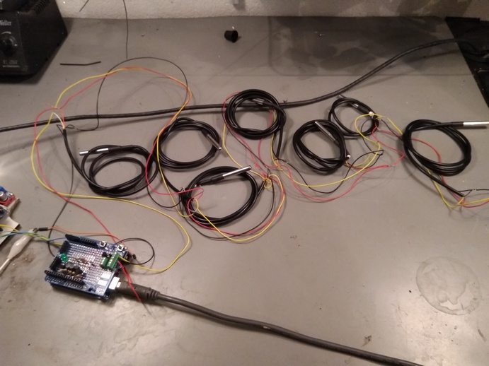
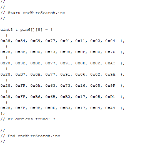
First I tested it with the "standard" Arduino dallas temperature sketch "oneWireSearch", I got up to 7 sensors in this one.
I connected the cable of the waterproof sensors to the three wires (GND, 5V and the onewire pin (pin7)), threaded and twisted together.
When I connect an 8th sensor, the search sketch says that no sensors can be found, it does not matter which sensor is the 8th.
If I connect the 7 sensors to the gateway node, I see the 7 sensors in domoticz, so that's where it is.
it is then 6 wired sensors and a sensor on the PCB.does anyone know if the onewire bus might be a twisted pair?
or is the distance between the branches too short?
If the problem remains, I just make extra oneWire bus for the 4 ground temperature sensors as you already suggested ... -
Thank you for your tips, at least I now have more knowledge about onewire.
Last night there was something else in between, but now I have put the sensors in a daisy chain (see photo).
First I tested it with the "standard" Arduino dallas temperature sketch "oneWireSearch", I got up to 7 sensors in this one.
I connected the cable of the waterproof sensors to the three wires (GND, 5V and the onewire pin (pin7)), threaded and twisted together.
When I connect an 8th sensor, the search sketch says that no sensors can be found, it does not matter which sensor is the 8th.
If I connect the 7 sensors to the gateway node, I see the 7 sensors in domoticz, so that's where it is.
it is then 6 wired sensors and a sensor on the PCB.does anyone know if the onewire bus might be a twisted pair?
or is the distance between the branches too short?
If the problem remains, I just make extra oneWire bus for the 4 ground temperature sensors as you already suggested ... -
@dzjr Now you have to figure out why only #8 did not work, so progress ;) even if a digital device on One-Wire has not yet sunk in...
There is no physical loop 8 I can see, so how is#8 connected in the chain?No, the 8th sensor is not connected because the search sketch does not find any sensor.
Even with a 9th sensor, the sketch unfortunately does not find anything.and indeed there is no loop, on the other side of the wires I connected a multimeter to measure the 5V / GND voltage.
The yellow bus wire has an open end.
I also tried to connect a sensor at the end of the line as the 8th sensor.
and I have used several sensors as "8th", so it is very likely that the sensors are okay -
@dzjr Sorry for any misunderstanding, the loops I was referring to are the sensor cable loops in your photo.
I did read somewhere that different pullup resistors were recommended by different suppliers of the waterproof versions, values from 10k to 2k2, rather than the usual 4k7, some said the pullup should be on the Arduino end, others on the last sensor on the line, so worth experimenting, perhaps even a sacrificial length of additional cable to alter or extend spacing ?
What is crucial to these devices is digital signal timing, hence constraints on layout architecture and cable capacitance, the pullup resistor only alters the circuit's speed of High/Low transitions.
Here bare DS18B20s on Cat5 cable (low capacitance) works fine on a 3v Arduino for 12 sensors, so it can be done. -
If you have access to an oscilloscope, see what the signal looks like at the end. I had a problem a while ago with too long cable for i2c. See https://forum.mysensors.org/post/92967 for pictures.
Stronger pullup at the end of the cable might help.
-
https://www.maximintegrated.com/en/app-notes/index.mvp/id/148
Here is maxim's guide on wiring for 1-wire. There are a few things to note, one is the "weight" of each sensor's cable. Read that section closely. Another is hubs. Hubs are basically a 1 wire switch that connects each segement of the network 1 at a time, so you can essentially walk though each ray of your star. The third is the suggestion above to use multiple pins on the arduino and just make several simpler networks.
I have had good luck with 1 wire but only after careful attention to the wiring itself. Star topology can work fine for several sensors, but daisy chain is important for less trouble, as mentioned.
Wiring comments: wiring is the most important thing.
-
Use a twisted pair cable (or twist your single conductor wires). Cat5 or telephone wire or similar works well. Solder all connections in the daisy chains or use wire nuts or terminal blocks, or other connectors. Do not just hand twist.
-
Your ground and + wires to the sensors should be connected directly to the board terminal closest to the power supply. Don't use skinny jumper wires or connect to a different convenient spot on the board, or to some other ground or +5 device connected to the board. (Yes, all +5 and ground terminals are not 'the same' when it comes to analog circuits.)
-
Don't run the wires in a bundle or nearby other wiring.
-
A lower value pull-up resistor is easy to try and may help. Another trick is adding a 100 ohm resistor in series where the 1-wire signal line connects to the board. (Disconnect wire from board, connect resistor to board, connect wire to resistor.)
Tim
-
-
@dzjr Sorry for any misunderstanding, the loops I was referring to are the sensor cable loops in your photo.
I did read somewhere that different pullup resistors were recommended by different suppliers of the waterproof versions, values from 10k to 2k2, rather than the usual 4k7, some said the pullup should be on the Arduino end, others on the last sensor on the line, so worth experimenting, perhaps even a sacrificial length of additional cable to alter or extend spacing ?
What is crucial to these devices is digital signal timing, hence constraints on layout architecture and cable capacitance, the pullup resistor only alters the circuit's speed of High/Low transitions.
Here bare DS18B20s on Cat5 cable (low capacitance) works fine on a 3v Arduino for 12 sensors, so it can be done.I replaced the resistor an 2K2 resistor, and now see all nine sensors, 2K2 resistor also works with a single sensor.
In the sketch I have now given all 9 sensors their own child ID, I only see no data from the 5th sensor, so I have to look at it next week, in the "test sketch" I see a temperature, so just have a look what is wrong.
The sensor network of 6 sensors I made in a daisy chain, and two sensors I made separately to the sensor node, and the 9th is fixed on the node's PCB.
Next week still good testing and make a small adjustment for sending the (temporary) rain sensor and then I hope to finally install everything.
Thank you very much for all the help and tips, I finally solved my "problem"!
dzjr
-
If you have access to an oscilloscope, see what the signal looks like at the end. I had a problem a while ago with too long cable for i2c. See https://forum.mysensors.org/post/92967 for pictures.
Stronger pullup at the end of the cable might help.
@mfalkvidd I have a oscilloscope but it is a old analog scope so i can't use it to analyse the 1wire singal.
But i have orderd a very simple logic analyzer for the next time i need one!.
The problem is now solved by using a 2K2 resistor istead of te regulear 4K7 resistor.
-
https://www.maximintegrated.com/en/app-notes/index.mvp/id/148
Here is maxim's guide on wiring for 1-wire. There are a few things to note, one is the "weight" of each sensor's cable. Read that section closely. Another is hubs. Hubs are basically a 1 wire switch that connects each segement of the network 1 at a time, so you can essentially walk though each ray of your star. The third is the suggestion above to use multiple pins on the arduino and just make several simpler networks.
Thank you for the link, i allready find that on a coffe break, but on the smartphone it is nog easy to read, so i read it this weekend on the laptop.
All the nine sensors are now working, i rearrenged the sensor network en used a 2K2 resistor in stead of a 4K7 resistor and that turned out to be the problem.
Thank you for helping
-
I have had good luck with 1 wire but only after careful attention to the wiring itself. Star topology can work fine for several sensors, but daisy chain is important for less trouble, as mentioned.
Wiring comments: wiring is the most important thing.
-
Use a twisted pair cable (or twist your single conductor wires). Cat5 or telephone wire or similar works well. Solder all connections in the daisy chains or use wire nuts or terminal blocks, or other connectors. Do not just hand twist.
-
Your ground and + wires to the sensors should be connected directly to the board terminal closest to the power supply. Don't use skinny jumper wires or connect to a different convenient spot on the board, or to some other ground or +5 device connected to the board. (Yes, all +5 and ground terminals are not 'the same' when it comes to analog circuits.)
-
Don't run the wires in a bundle or nearby other wiring.
-
A lower value pull-up resistor is easy to try and may help. Another trick is adding a 100 ohm resistor in series where the 1-wire signal line connects to the board. (Disconnect wire from board, connect resistor to board, connect wire to resistor.)
Tim
@grubstake I now have used a 4 wire YCY (screened signal cable), and that also is working ( 9 sensors on one pin).
Ultimately, the use of a 2K2 resistor was a good solutionDo you recommend to use the 5 volt of the arduino, or is it better to use the 5 volts which I use as power supply of the arduino?
And can I or should I put the ground of the sensors on the arduino?
-