Multiple Dallas Temperatuur sensors at one sensor node
-
https://www.maximintegrated.com/en/app-notes/index.mvp/id/148
Here is maxim's guide on wiring for 1-wire. There are a few things to note, one is the "weight" of each sensor's cable. Read that section closely. Another is hubs. Hubs are basically a 1 wire switch that connects each segement of the network 1 at a time, so you can essentially walk though each ray of your star. The third is the suggestion above to use multiple pins on the arduino and just make several simpler networks.
I have had good luck with 1 wire but only after careful attention to the wiring itself. Star topology can work fine for several sensors, but daisy chain is important for less trouble, as mentioned.
Wiring comments: wiring is the most important thing.
-
Use a twisted pair cable (or twist your single conductor wires). Cat5 or telephone wire or similar works well. Solder all connections in the daisy chains or use wire nuts or terminal blocks, or other connectors. Do not just hand twist.
-
Your ground and + wires to the sensors should be connected directly to the board terminal closest to the power supply. Don't use skinny jumper wires or connect to a different convenient spot on the board, or to some other ground or +5 device connected to the board. (Yes, all +5 and ground terminals are not 'the same' when it comes to analog circuits.)
-
Don't run the wires in a bundle or nearby other wiring.
-
A lower value pull-up resistor is easy to try and may help. Another trick is adding a 100 ohm resistor in series where the 1-wire signal line connects to the board. (Disconnect wire from board, connect resistor to board, connect wire to resistor.)
Tim
-
-
@dzjr Sorry for any misunderstanding, the loops I was referring to are the sensor cable loops in your photo.
I did read somewhere that different pullup resistors were recommended by different suppliers of the waterproof versions, values from 10k to 2k2, rather than the usual 4k7, some said the pullup should be on the Arduino end, others on the last sensor on the line, so worth experimenting, perhaps even a sacrificial length of additional cable to alter or extend spacing ?
What is crucial to these devices is digital signal timing, hence constraints on layout architecture and cable capacitance, the pullup resistor only alters the circuit's speed of High/Low transitions.
Here bare DS18B20s on Cat5 cable (low capacitance) works fine on a 3v Arduino for 12 sensors, so it can be done.I replaced the resistor an 2K2 resistor, and now see all nine sensors, 2K2 resistor also works with a single sensor.
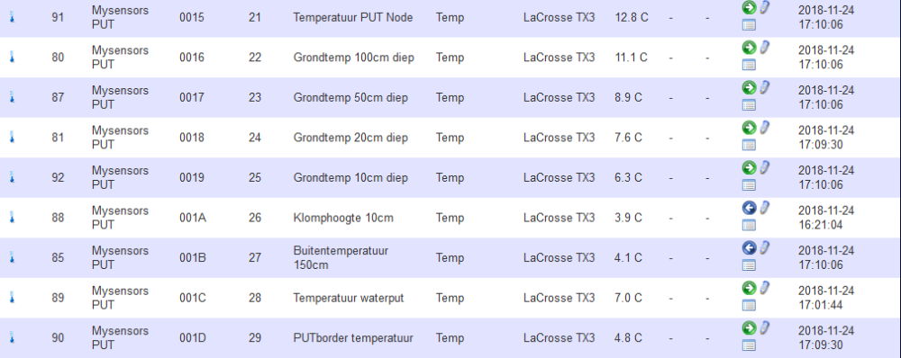
In the sketch I have now given all 9 sensors their own child ID, I only see no data from the 5th sensor, so I have to look at it next week, in the "test sketch" I see a temperature, so just have a look what is wrong.
The sensor network of 6 sensors I made in a daisy chain, and two sensors I made separately to the sensor node, and the 9th is fixed on the node's PCB.
Next week still good testing and make a small adjustment for sending the (temporary) rain sensor and then I hope to finally install everything.
Thank you very much for all the help and tips, I finally solved my "problem"!
dzjr
-
If you have access to an oscilloscope, see what the signal looks like at the end. I had a problem a while ago with too long cable for i2c. See https://forum.mysensors.org/post/92967 for pictures.
Stronger pullup at the end of the cable might help.
@mfalkvidd I have a oscilloscope but it is a old analog scope so i can't use it to analyse the 1wire singal.
But i have orderd a very simple logic analyzer for the next time i need one!.
The problem is now solved by using a 2K2 resistor istead of te regulear 4K7 resistor.
-
https://www.maximintegrated.com/en/app-notes/index.mvp/id/148
Here is maxim's guide on wiring for 1-wire. There are a few things to note, one is the "weight" of each sensor's cable. Read that section closely. Another is hubs. Hubs are basically a 1 wire switch that connects each segement of the network 1 at a time, so you can essentially walk though each ray of your star. The third is the suggestion above to use multiple pins on the arduino and just make several simpler networks.
Thank you for the link, i allready find that on a coffe break, but on the smartphone it is nog easy to read, so i read it this weekend on the laptop.
All the nine sensors are now working, i rearrenged the sensor network en used a 2K2 resistor in stead of a 4K7 resistor and that turned out to be the problem.
Thank you for helping
-
I have had good luck with 1 wire but only after careful attention to the wiring itself. Star topology can work fine for several sensors, but daisy chain is important for less trouble, as mentioned.
Wiring comments: wiring is the most important thing.
-
Use a twisted pair cable (or twist your single conductor wires). Cat5 or telephone wire or similar works well. Solder all connections in the daisy chains or use wire nuts or terminal blocks, or other connectors. Do not just hand twist.
-
Your ground and + wires to the sensors should be connected directly to the board terminal closest to the power supply. Don't use skinny jumper wires or connect to a different convenient spot on the board, or to some other ground or +5 device connected to the board. (Yes, all +5 and ground terminals are not 'the same' when it comes to analog circuits.)
-
Don't run the wires in a bundle or nearby other wiring.
-
A lower value pull-up resistor is easy to try and may help. Another trick is adding a 100 ohm resistor in series where the 1-wire signal line connects to the board. (Disconnect wire from board, connect resistor to board, connect wire to resistor.)
Tim
@grubstake I now have used a 4 wire YCY (screened signal cable), and that also is working ( 9 sensors on one pin).
Ultimately, the use of a 2K2 resistor was a good solutionDo you recommend to use the 5 volt of the arduino, or is it better to use the 5 volts which I use as power supply of the arduino?
And can I or should I put the ground of the sensors on the arduino?
-
-
@grubstake I now have used a 4 wire YCY (screened signal cable), and that also is working ( 9 sensors on one pin).
Ultimately, the use of a 2K2 resistor was a good solutionDo you recommend to use the 5 volt of the arduino, or is it better to use the 5 volts which I use as power supply of the arduino?
And can I or should I put the ground of the sensors on the arduino?
@dzjr I believe the point @Grubstake was making is to ensure solid and stable connection for voltage and ground to the board itself, not elsewhere, the issue is to ensure stability.
Glad the stronger pullup solved your problem but would caution on choice of cable. Telephone wire or Cat5 as also stated is known to work well and reliably for One-Wire, is cheap and readily available. Screening or grounding unused cores does affect capacitance, which may lead to problems in final layout. -
Thanks again for your help, last weekend I installed everything outside, and everything remains stable!
The only "problem" I still have is that the resolution of the sensors is 9 Bit, while I prefer to have an 11 or 12 bit resolution.
now I have made a second setup with two sensors and the same sketch (only name and IP address are different) and that gives a 12 bit resolution.
Is this because I have connected 9 sensors, or is there possibly something wrong with the reading time in the sketch?
Or is it just a programming error?the whole sketch is a bit big to post, so I cut it into pieces.
before:
// Dallas temp stukje
#define COMPARE_TEMP 1 // 1= zenden alleen bij verandering 0= direct zenden
#define ONE_WIRE_BUS 6
#define TEMPERATURE_PRECISION 12
#define MAX_ATTACHED_DS18B20 13
unsigned long SLEEP_TIME = 300; //slaaptijd tussen twee metingen in ms
OneWire oneWire(ONE_WIRE_BUS); //Een oneWire-exemplaar instellen om te communiceren met alle OneWire-apparaten
DallasTemperature sensors(&oneWire); //OneWire naar Dallas
float lastTemperature[MAX_ATTACHED_DS18B20];
int numSensors=0;
bool receivedConfig = false;
bool metric = true;

DeviceAddress Probe01 = { 0x28, 0xFF, 0x64, 0x1D, 0xF8, 0x4F, 0x3A, 0x08 }; // op print
DeviceAddress Probe02 = { 0x28, 0xFF, 0x64, 0x1D, 0xF9, 0x9D, 0xDC, 0x5E  }; // temp op -100 cm
DeviceAddress Probe03 = { 0x28, 0xED, 0x25, 0x77, 0x91, 0x13, 0x02, 0xFF }; // temp op -50 mtr
DeviceAddress Probe04 = { 0x28, 0xC5, 0x51, 0x77, 0x91, 0x0B, 0x02, 0x00 }; // temp op -20 cm
DeviceAddress Probe05 = { 0x28, 0xDC, 0x25, 0x77, 0x91, 0x13, 0x02, 0x25 }; // temp op -10 cm
DeviceAddress Probe06 = { 0x28, 0x54, 0x96, 0x77, 0x91, 0x08, 0x02, 0xA0 }; // temp op 10 cm
DeviceAddress Probe07 = { 0x28, 0x1F, 0x11, 0x43, 0x98, 0x25, 0x00, 0x8B }; // temp op 150 cm
DeviceAddress Probe08 = { 0x28, 0xFF, 0x0A, 0x63, 0x73, 0x16, 0x05, 0x9F }; // temp van water in put
DeviceAddress Probe09 = { 0x28, 0x98, 0x9C, 0x77, 0x91, 0x19, 0x02, 0xD7 }; // temp in border


// Initialiseer temperatuurbericht
MyMessage msg(0, V_TEMP);
Void Loop:
void loop()

{
{
  // Fetch temperatures from Dallas sensors
  sensors.requestTemperatures();

  // query conversion time and sleep until conversion completed
  int16_t conversionTime = sensors.millisToWaitForConversion(sensors.getResolution());

  wait(conversionTime);

  // Read temperatures and send them to controller
  for (int i=0; i<numSensors && i<MAX_ATTACHED_DS18B20; i++) {

    // Fetch and round temperature to one decimal
   // float temperature = static_cast<float>(static_cast<int>((getControllerConfig().isMetric?sensors.getTempCByIndex(i):sensors.getTempFByIndex(i)) * 10.)) / 10.;
  float temperature;
    // voor geadreseerde sensoren
    switch (i)  {
      case 0:
        temperature = sensors.getTempC(Probe01);
        break;
      case 1:
        temperature = sensors.getTempC(Probe02);
        break;
      case 2:
        temperature = sensors.getTempC(Probe03);
        break;
      case 3:
        temperature = sensors.getTempC(Probe04);
        break;
      case 4:
        temperature = sensors.getTempC(Probe05);
        break;
      case 5:
        temperature = sensors.getTempC(Probe06);
        break;
      case 6:
        temperature = sensors.getTempC(Probe07);
        break;
      case 7:
        temperature = sensors.getTempC(Probe08);
        break;
      case 8:
        temperature = sensors.getTempC(Probe09);
        break;
      default:
        temperature = sensors.getTempCByIndex(Probe09);
        break;
    }

    // Only send data if temperature has changed and no error
    #if COMPARE_TEMP == 1
    if (lastTemperature[i] != temperature && temperature != -127.00 && temperature != 85.00) {
    #else
    if (temperature != -127.00 && temperature != 85.00) {
    #endif

      // Send in the new temperature
      send(msg.setSensor(i+21).set(temperature,1));
      // Save new temperatures for next compare
      lastTemperature[i]=temperature;
    }
    }
    }
The complete code you can find here; sorry the comments are in dutch...
https://github.com/dzjr/MySensors-Put-NodeThis was my first real MySensor and second Arduino sketch / project, so if you have some comments or tips, I am open to that!
Thank you for the help!
dzjr
-
Thanks again for your help, last weekend I installed everything outside, and everything remains stable!
The only "problem" I still have is that the resolution of the sensors is 9 Bit, while I prefer to have an 11 or 12 bit resolution.
now I have made a second setup with two sensors and the same sketch (only name and IP address are different) and that gives a 12 bit resolution.
Is this because I have connected 9 sensors, or is there possibly something wrong with the reading time in the sketch?
Or is it just a programming error?the whole sketch is a bit big to post, so I cut it into pieces.
before:
// Dallas temp stukje
#define COMPARE_TEMP 1 // 1= zenden alleen bij verandering 0= direct zenden
#define ONE_WIRE_BUS 6
#define TEMPERATURE_PRECISION 12
#define MAX_ATTACHED_DS18B20 13
unsigned long SLEEP_TIME = 300; //slaaptijd tussen twee metingen in ms
OneWire oneWire(ONE_WIRE_BUS); //Een oneWire-exemplaar instellen om te communiceren met alle OneWire-apparaten
DallasTemperature sensors(&oneWire); //OneWire naar Dallas
float lastTemperature[MAX_ATTACHED_DS18B20];
int numSensors=0;
bool receivedConfig = false;
bool metric = true;

DeviceAddress Probe01 = { 0x28, 0xFF, 0x64, 0x1D, 0xF8, 0x4F, 0x3A, 0x08 }; // op print
DeviceAddress Probe02 = { 0x28, 0xFF, 0x64, 0x1D, 0xF9, 0x9D, 0xDC, 0x5E  }; // temp op -100 cm
DeviceAddress Probe03 = { 0x28, 0xED, 0x25, 0x77, 0x91, 0x13, 0x02, 0xFF }; // temp op -50 mtr
DeviceAddress Probe04 = { 0x28, 0xC5, 0x51, 0x77, 0x91, 0x0B, 0x02, 0x00 }; // temp op -20 cm
DeviceAddress Probe05 = { 0x28, 0xDC, 0x25, 0x77, 0x91, 0x13, 0x02, 0x25 }; // temp op -10 cm
DeviceAddress Probe06 = { 0x28, 0x54, 0x96, 0x77, 0x91, 0x08, 0x02, 0xA0 }; // temp op 10 cm
DeviceAddress Probe07 = { 0x28, 0x1F, 0x11, 0x43, 0x98, 0x25, 0x00, 0x8B }; // temp op 150 cm
DeviceAddress Probe08 = { 0x28, 0xFF, 0x0A, 0x63, 0x73, 0x16, 0x05, 0x9F }; // temp van water in put
DeviceAddress Probe09 = { 0x28, 0x98, 0x9C, 0x77, 0x91, 0x19, 0x02, 0xD7 }; // temp in border


// Initialiseer temperatuurbericht
MyMessage msg(0, V_TEMP);
Void Loop:
void loop()

{
{
  // Fetch temperatures from Dallas sensors
  sensors.requestTemperatures();

  // query conversion time and sleep until conversion completed
  int16_t conversionTime = sensors.millisToWaitForConversion(sensors.getResolution());

  wait(conversionTime);

  // Read temperatures and send them to controller
  for (int i=0; i<numSensors && i<MAX_ATTACHED_DS18B20; i++) {

    // Fetch and round temperature to one decimal
   // float temperature = static_cast<float>(static_cast<int>((getControllerConfig().isMetric?sensors.getTempCByIndex(i):sensors.getTempFByIndex(i)) * 10.)) / 10.;
  float temperature;
    // voor geadreseerde sensoren
    switch (i)  {
      case 0:
        temperature = sensors.getTempC(Probe01);
        break;
      case 1:
        temperature = sensors.getTempC(Probe02);
        break;
      case 2:
        temperature = sensors.getTempC(Probe03);
        break;
      case 3:
        temperature = sensors.getTempC(Probe04);
        break;
      case 4:
        temperature = sensors.getTempC(Probe05);
        break;
      case 5:
        temperature = sensors.getTempC(Probe06);
        break;
      case 6:
        temperature = sensors.getTempC(Probe07);
        break;
      case 7:
        temperature = sensors.getTempC(Probe08);
        break;
      case 8:
        temperature = sensors.getTempC(Probe09);
        break;
      default:
        temperature = sensors.getTempCByIndex(Probe09);
        break;
    }

    // Only send data if temperature has changed and no error
    #if COMPARE_TEMP == 1
    if (lastTemperature[i] != temperature && temperature != -127.00 && temperature != 85.00) {
    #else
    if (temperature != -127.00 && temperature != 85.00) {
    #endif

      // Send in the new temperature
      send(msg.setSensor(i+21).set(temperature,1));
      // Save new temperatures for next compare
      lastTemperature[i]=temperature;
    }
    }
    }
The complete code you can find here; sorry the comments are in dutch...
https://github.com/dzjr/MySensors-Put-NodeThis was my first real MySensor and second Arduino sketch / project, so if you have some comments or tips, I am open to that!
Thank you for the help!
dzjr
@dzjr Check out the read times on the Dallas specs, from memory it increases markedly with higher resolutions....
-
Thanks again for your help, last weekend I installed everything outside, and everything remains stable!
The only "problem" I still have is that the resolution of the sensors is 9 Bit, while I prefer to have an 11 or 12 bit resolution.
now I have made a second setup with two sensors and the same sketch (only name and IP address are different) and that gives a 12 bit resolution.
Is this because I have connected 9 sensors, or is there possibly something wrong with the reading time in the sketch?
Or is it just a programming error?the whole sketch is a bit big to post, so I cut it into pieces.
before:
// Dallas temp stukje
#define COMPARE_TEMP 1 // 1= zenden alleen bij verandering 0= direct zenden
#define ONE_WIRE_BUS 6
#define TEMPERATURE_PRECISION 12
#define MAX_ATTACHED_DS18B20 13
unsigned long SLEEP_TIME = 300; //slaaptijd tussen twee metingen in ms
OneWire oneWire(ONE_WIRE_BUS); //Een oneWire-exemplaar instellen om te communiceren met alle OneWire-apparaten
DallasTemperature sensors(&oneWire); //OneWire naar Dallas
float lastTemperature[MAX_ATTACHED_DS18B20];
int numSensors=0;
bool receivedConfig = false;
bool metric = true;

DeviceAddress Probe01 = { 0x28, 0xFF, 0x64, 0x1D, 0xF8, 0x4F, 0x3A, 0x08 }; // op print
DeviceAddress Probe02 = { 0x28, 0xFF, 0x64, 0x1D, 0xF9, 0x9D, 0xDC, 0x5E  }; // temp op -100 cm
DeviceAddress Probe03 = { 0x28, 0xED, 0x25, 0x77, 0x91, 0x13, 0x02, 0xFF }; // temp op -50 mtr
DeviceAddress Probe04 = { 0x28, 0xC5, 0x51, 0x77, 0x91, 0x0B, 0x02, 0x00 }; // temp op -20 cm
DeviceAddress Probe05 = { 0x28, 0xDC, 0x25, 0x77, 0x91, 0x13, 0x02, 0x25 }; // temp op -10 cm
DeviceAddress Probe06 = { 0x28, 0x54, 0x96, 0x77, 0x91, 0x08, 0x02, 0xA0 }; // temp op 10 cm
DeviceAddress Probe07 = { 0x28, 0x1F, 0x11, 0x43, 0x98, 0x25, 0x00, 0x8B }; // temp op 150 cm
DeviceAddress Probe08 = { 0x28, 0xFF, 0x0A, 0x63, 0x73, 0x16, 0x05, 0x9F }; // temp van water in put
DeviceAddress Probe09 = { 0x28, 0x98, 0x9C, 0x77, 0x91, 0x19, 0x02, 0xD7 }; // temp in border


// Initialiseer temperatuurbericht
MyMessage msg(0, V_TEMP);
Void Loop:
void loop()

{
{
  // Fetch temperatures from Dallas sensors
  sensors.requestTemperatures();

  // query conversion time and sleep until conversion completed
  int16_t conversionTime = sensors.millisToWaitForConversion(sensors.getResolution());

  wait(conversionTime);

  // Read temperatures and send them to controller
  for (int i=0; i<numSensors && i<MAX_ATTACHED_DS18B20; i++) {

    // Fetch and round temperature to one decimal
   // float temperature = static_cast<float>(static_cast<int>((getControllerConfig().isMetric?sensors.getTempCByIndex(i):sensors.getTempFByIndex(i)) * 10.)) / 10.;
  float temperature;
    // voor geadreseerde sensoren
    switch (i)  {
      case 0:
        temperature = sensors.getTempC(Probe01);
        break;
      case 1:
        temperature = sensors.getTempC(Probe02);
        break;
      case 2:
        temperature = sensors.getTempC(Probe03);
        break;
      case 3:
        temperature = sensors.getTempC(Probe04);
        break;
      case 4:
        temperature = sensors.getTempC(Probe05);
        break;
      case 5:
        temperature = sensors.getTempC(Probe06);
        break;
      case 6:
        temperature = sensors.getTempC(Probe07);
        break;
      case 7:
        temperature = sensors.getTempC(Probe08);
        break;
      case 8:
        temperature = sensors.getTempC(Probe09);
        break;
      default:
        temperature = sensors.getTempCByIndex(Probe09);
        break;
    }

    // Only send data if temperature has changed and no error
    #if COMPARE_TEMP == 1
    if (lastTemperature[i] != temperature && temperature != -127.00 && temperature != 85.00) {
    #else
    if (temperature != -127.00 && temperature != 85.00) {
    #endif

      // Send in the new temperature
      send(msg.setSensor(i+21).set(temperature,1));
      // Save new temperatures for next compare
      lastTemperature[i]=temperature;
    }
    }
    }
The complete code you can find here; sorry the comments are in dutch...
https://github.com/dzjr/MySensors-Put-NodeThis was my first real MySensor and second Arduino sketch / project, so if you have some comments or tips, I am open to that!
Thank you for the help!
dzjr
@dzjr you have the define
#define TEMPERATURE_PRECISION 12In the github code this is not utilized, so the sensors are operating in 9 bit resolution.
You need to add the following in the before or setup
sensors.setResolution(TEMPERATURE_PRECISION); -
@dzjr you have the define
#define TEMPERATURE_PRECISION 12In the github code this is not utilized, so the sensors are operating in 9 bit resolution.
You need to add the following in the before or setup
sensors.setResolution(TEMPERATURE_PRECISION);Thanks for the reply, i have tryed to load the new sketch into the Arduino, only i cant make USB connection, do i have look at that first 😕.
You will hear from me.
Dzjr
-
after replacing the arduino (I could not connect the board) I was able to load the sketch again.
I now have a better resolution, I do not think I have 12 bits but maybe that's because of the link with domoticz.
As I wrote the node is installed, but still think that I must adapt to the sketch.
I now only have a dallas sensor that does not work anymore, but that will be okay.
-
@mfalkvidd Yes i know that, i allready read it in the spec sheet.
-
after replacing the arduino (I could not connect the board) I was able to load the sketch again.
I now have a better resolution, I do not think I have 12 bits but maybe that's because of the link with domoticz.
As I wrote the node is installed, but still think that I must adapt to the sketch.
I now only have a dallas sensor that does not work anymore, but that will be okay.
-
@dzjr To get the extra resolution sent to the controller try using
send(msg.setSensor(i+21).set(temperature,2));@hard-shovel I will keep that in mind,
for now it is working (only one dallas is broken).
-
@zboblamont said in Multiple Dallas Temperatuur sensors at one sensor node:
If you cannot daisy chain them because there is no sequential route between locations, use a separate pin for each data line (powered via resistor) and communicate with each line in turn.
The line here is using 3 cores in 20-30m of Cat5e cable to ensure each chip is physically sequential on the line.
When I added a further sensor location, a loop had to be spliced in to keep the line a daisy chain. It is a small house, the length is purely down to the route, and cable is cheap.in case you can not daisy chain them because there is no sequential direction among locations, use a separate pin for each data line (powered thru resistor) and talk with each line in flip.
the road here is using three cores in 20-30m of Cat5e cable to make certain each chip is physically sequential on the road.
after I delivered a similarly sensor vicinity, a loop needed to be spliced in to preserve the road a daisy chain. it is a small residence, the period is purely down to the route, and cable is cheap.
Hello! It looks like you're interested in this conversation, but you don't have an account yet.
Getting fed up of having to scroll through the same posts each visit? When you register for an account, you'll always come back to exactly where you were before, and choose to be notified of new replies (either via email, or push notification). You'll also be able to save bookmarks and upvote posts to show your appreciation to other community members.
With your input, this post could be even better 💗
Register Login