The script for 'Example with button' works perfectly! Thanks for that.
Has someone a script for multiple Relays with buttons ready to use for me?
I want to use it in my garden to switch the lights with physical buttons and also control them with Domoticz.
b0wi
Posts
-
💬 Relay -
💬 Building a WiFi Gateway using ESP8266@mfalkvidd said in 💬 Building a WiFi Gateway using ESP8266:
Indication leds: the same pin can be used. Pro: only one pin is needed. Con: you won't be able to see the type of indication. An alternaive, if you can't find enough pins, is to only activate one or two.
Inclusion: hopefully someone else can assist. I have never used inclusion.
It's working now!
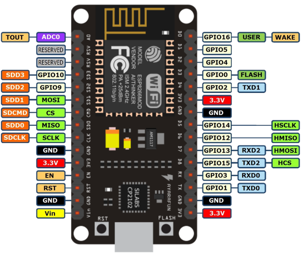
I'm using the following pins for the leds:// Flash leds on rx/tx/err // Led pins used if blinking feature is enabled above #define MY_DEFAULT_ERR_LED_PIN 0 // [D3 / GPIO 0] Error led pin (Red) #define MY_DEFAULT_RX_LED_PIN 2 // [D4 / GPIO 2] Receive led pin (Green) #define MY_DEFAULT_TX_LED_PIN 16 // [D0 / GPIO 16] Send led pin (Yellow)
The leds where on all the time except when there was some activity, so I had to invent the leds:
// Inverses the behavior of leds
#define MY_WITH_LEDS_BLINKING_INVERSE
For the inclusion button I've used:
// Digital pin used for inclusion mode button
#define MY_INCLUSION_MODE_BUTTON_PIN 5 // [D1 / GPIO 5] Button pin
I needed to use an pull up resistor (10K ohm) for more stability.

-
💬 Building a WiFi Gateway using ESP8266Thanks @mfalkvidd, I'm using this board: https://nl.aliexpress.com/item/NodeMcu-Lua-WIFI-Internet-of-Things-development-board-based-ESP8266-module/32448461056.html?spm=a2g0s.13010208.99999999.329.1df83c00aOlGkL
I've to use different pins for each LED right?
// Flash leds on rx/tx/err
// Led pins used if blinking feature is enabled above
#define MY_DEFAULT_ERR_LED_PIN 16 // Error led pin
#define MY_DEFAULT_RX_LED_PIN 16 // Receive led pin
#define MY_DEFAULT_TX_LED_PIN 16 // the PCB, on board LED
And how can I test my inclusion button?
Is there something to see in the log output? -
💬 Building a WiFi Gateway using ESP8266Hello! I'm so happy with the MySensors community the forum helped me so much to find answers, but I can't figure out the following:
I'm building an Wi-Fi Gateway using an ESP8266. That gateway is running now but I want to add the LEDS and inclusion mode button. In the comments of the code I find out that I have to use pin 16 for all the leds?// Flash leds on rx/tx/err // Led pins used if blinking feature is enabled above #define MY_DEFAULT_ERR_LED_PIN 16 // Error led pin #define MY_DEFAULT_RX_LED_PIN 16 // Receive led pin #define MY_DEFAULT_TX_LED_PIN 16 // the PCB, on board LEDIs that correct? And with D? Pin do I have to use?
For the inclusion mode button I have to use pin D1:
// Digital pin used for inclusion mode button
#define MY_INCLUSION_MODE_BUTTON_PIN D1
But I can't compile this because I have to use an pin number and not just D1. How can I fix that? And how can I test/debug the button to see of it's in the inclusion mode?
Thanks in advance!
Robin
