Navigation

    • Register
    • Login
    • OpenHardware.io
    • Categories
    • Recent
    • Tags
    • Popular
    1. Home
    2. dzjr
    3. Posts
    • Profile
    • Following
    • Followers
    • Topics
    • Posts
    • Best
    • Groups

    Posts made by dzjr

    • RE: Air Quality sensor CJMCU-8118

      @skywatch

      Thank you for your response,

      Of course I also used the separate (test) sketch to test, I also arrive at the end of the measuring range, with one of the combined, and with the second (had ordered two) I don't get any measurements at all, unfortunately.

      The HDC sensor does send values, and with the IΒ²C scanner I also see two sensors, but the CCS gives me no or incorrect values.

      I'll just say that I bought a fake sensor, I will now just order a separate CCS-811.

      Just understood that the CCS-811 does not need to be called, because first chose the BME860, but I didn't get any good value from that, I think because the calibration is not going well.
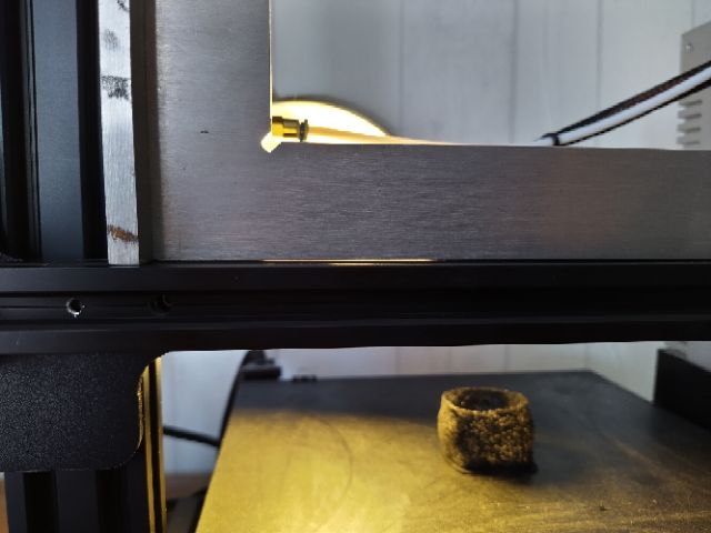
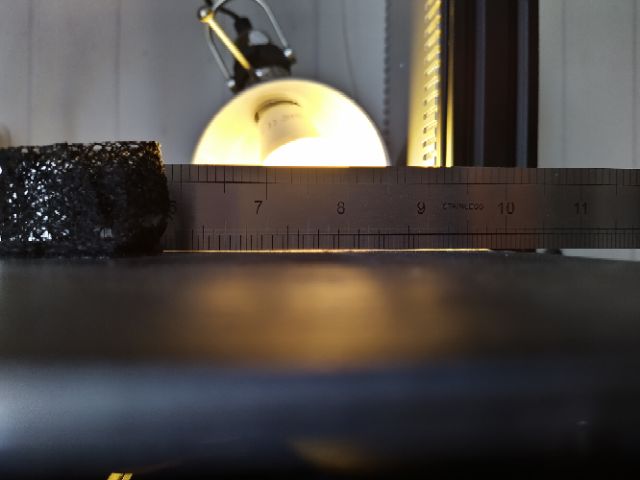
      posted in Hardware
      dzjr
      dzjr
    • Air Quality sensor CJMCU-8118

      Hello MYSensors friends,

      I am making some air quality & temp/hum sensors for the home, I have already finished the first one with a BME280 and a CCS-811 sensor that also works, including an rgb led.

      For the other sensors I ordered a CJMCU-8118, which is actually a CCS-811 and an HDC-1080 in one, so that saves some space on the assembly.

      Only now I run into the problem that the CCS-811 part indicates extremely high values, while the other sensor with the separate CCS-811 gives low values ...

      I used the same scketch for both, only replaced a BME part for the HDC.

      Does any of you know how it is possible that the combined sensor indicates such a high value, the sensor has now been burned in for over a day.

      or maybe someone has another option without me having to calibrate the sensors first.
      I am not concerned with exact values, but simply an indication of the air quality.

      thank you!
      dzjr

      posted in Hardware
      dzjr
      dzjr
    • RE: πŸ’¬ Simple compact RS485 node (ATmega328 + MAX485)

      @cabat The PCBs have been delivered !!

      only now the weather is very nice here, so I don't feel like hanging out in the workshop ...

      I'll let you know when I'm ready!

      posted in OpenHardware.io
      dzjr
      dzjr
    • RE: Best 3d printers

      @NeverDie
      I got the IKEA LOTS, and the results seem a little better, but still not stable.

      Sometimes slightly up, then down again.

      if I do the trick with the piece of paper and make sure that the piece of paper is just attached, so making a line of the filament, I have to adjust some wheels again every time.

      Unfortunately, the supplier of the printer did not respond, so I have no support for that, unfortunately.

      As a last option I will place the nuts, and possibly remove the springs completely from the print bed.

      I probably do something very stupid wrong and it turns out to be a menu error somewhere deep in the settings or something.

      I now have a raspberryPi with octoprint attached to the printer.

      posted in Enclosures / 3D Printing
      dzjr
      dzjr
    • RE: Best 3d printers

      @NeverDie

      i have checked the bed, it looks like it is not flat, also the horizontal profile is not flat.

      i am now trying to sell it.....

      ![alt text](IMG_20200622_145639_4.jpg image url)

      IMG_20200622_145543_4.jpg

      posted in Enclosures / 3D Printing
      dzjr
      dzjr
    • RE: Best 3d printers

      @NeverDie
      The main "problem" is that I just cannot get the bed stable, I will get an IKEA LOTS first, and I will take the printer out and assemble it again.

      I understand that the printer needs to be adjusted, but I am a little disappointed that the YouTube videos pretend that it is a job of 5 to 10 minutes, but it takes more than 10 days for me ...
      Apparently I put something wrong together, I will watch the CHEP video again.

      I'm going to take the printer completely apart and then reassemble it piece by piece, and then I'll post the result.

      posted in Enclosures / 3D Printing
      dzjr
      dzjr
    • RE: Best 3d printers

      @BearWithBeard Thank you for your response,

      I do notice that the print nozzle runs free on the sides, and gets stuck in the middle ....

      and that the back seems more stable than the front, the springs behind are much tighter.

      I will visit IKEA next week and purchase the LOTS.

      posted in Enclosures / 3D Printing
      dzjr
      dzjr
    • RE: Best 3d printers

      Well, so I bought the Ender3, but can't say it's a good buy ....

      To be honest, I regret it very much and am thinking about getting rid of it.

      I have had the printer for over two weeks now, and have been leveling the bed every night for two weeks.

      I have already taken the printer apart and reassembled it with a square hook, but that does not help.

      If I think that the bed has been leveled correctly and again prints a test print from here, the second print does not go well ....

      Yes, I heated bed (45 degrees C) before leveling.
      and I already have several youtube videos where they say, leveling is an easy job ...

      Does anyone have a tip?
      Or is choosing a different 3D printer a better idea?

      posted in Enclosures / 3D Printing
      dzjr
      dzjr
    • RE: πŸ’¬ Simple compact RS485 node (ATmega328 + MAX485)

      @cabat

      The PCB's i orderd are also send friday.

      So i hope is came this week!

      posted in OpenHardware.io
      dzjr
      dzjr
    • RE: Best 3d printers

      @pptacek

      Than i will order the Ender-3!

      maybe when i will buy another printer later, but we will see.

      posted in Enclosures / 3D Printing
      dzjr
      dzjr
    • RE: Best 3d printers

      @pptacek Thank you,

      Clear explanation, it certainly has an important difference.

      Do you think I have to pay a significant amount for the FFCP to improve it?

      I had more or less opted for the Ender-3, but I can still opt for the FFCP ...

      I understand that it is not a cheap hobby, hence the question of what is the best buy for me as a start.

      posted in Enclosures / 3D Printing
      dzjr
      dzjr
    • RE: Best 3d printers

      @alowhum

      I also think I'm going to buy an Ender-3,
      The difference between the 3 and the 3-Pro turns out not to be very big, in this video they tell the differences.

      If I would like to have a larger / other later, the costs are manageable, I think ....
      Or is the Flashforge Creator really worth the extra money (my dad wants to contribute too)?

      Thank you for explaining the Raspberry Pi addition,
      I have already seen a tutorial how it works, I still have a Pi-3 and Pi-2, which I can use nicely, also in combination with a camera.

      posted in Enclosures / 3D Printing
      dzjr
      dzjr
    • RE: Best 3d printers

      @alowhum

      Thank you for your response to my message,
      It took a little longer on this side because my work took a lot of time this week.

      I have read through part of the link, and keep reading that the Ender-3 (pro) would be the best choice?

      Of the Prusa i3, I read on the Dutch platform Tweakers.net that there are some safety aspects, so would the power supply not be fireproof?

      So if I see your message like this it would end up on the Ender 3 (Pro?)
      Also thanks to @pptacek's response

      How did you mean the touch screen? do you mean that you actually have to replace the controller with a Raspberry pi?

      posted in Enclosures / 3D Printing
      dzjr
      dzjr
    • RE: Best 3d printers

      @pptacek
      Thank you for your response to my message,
      It took a little longer on this side because my work took a lot of time this week.

      1 & 2 will not apply to me either, I may not have 3D printing experience, but I have enough technical skills to adjust and assemble something, but I don't want to be able to print something first. half an hour to adjust everything.

      So if I see your message like this, it would end up on the Ender 3 (Pro?) Or the Flashforge Creator Pro.
      I was thinking of max € 500 myself, but is it worth the price difference of about € 400?

      Ender 3 = € 180
      Ender 3-Pro = € 235
      Flashforge Creater Pro = 625

      posted in Enclosures / 3D Printing
      dzjr
      dzjr
    • RE: Best 3d printers

      MySensors Friends,

      I also plan to finally purchase a 3D printer.

      What do you recommend for a beginner right now?

      What do I want to make?
      Enclosures for sensors.
      small parts .
      and who knows what else in the future.

      So I am looking for a 3D printer that I can gain experience with as a beginner.
      Β  not too small, maintenance friendly, but that does not mean that I do not want to carry out maintenance.

      I don't really know yet what material I want to print with, what is the best and most versatile material to start with?

      Thank you in advance for your advice and thinking along.

      dzjr

      posted in Enclosures / 3D Printing
      dzjr
      dzjr
    • RE: πŸ’¬ Simple compact RS485 node (ATmega328 + MAX485)

      @cabat unfortunately i am still waiting for the pcb's so i could try it unfortunately ...
      Still listed as "In Fabrication" hope it comes soon ...

      in the meantime I have received all parts

      posted in OpenHardware.io
      dzjr
      dzjr
    • RE: Your workshop :)

      @skywatch that is looking very good, but why would you measure the wind speed of your workshop?
      πŸ˜‡

      posted in General Discussion
      dzjr
      dzjr
    • Kind message & thank you all

      Hello MySensors friends,

      I have been building MySensors nodes for various applications for a while now, and I have learned a lot thanks to you and this forum.

      To give something in return, I recently made a donation to support the network, and I would like to thank you extra by posting this here.

      What I especially notice about this forum is that the users are generally very helpful and friendly.

      Normally I am not such a forum user because in many Dutch forums there are always some users who find their self important, and who like to take someone down.
      Fortunately I notice very little of this here on the MySensors forum, thank you for that !!

      I will soon post some projects that I have made.

      I ❀ MySensors!

      Thank you!

      posted in General Discussion
      dzjr
      dzjr
    • RS-232 in a MySensors RS485 network for GSM/SMS modem

      Friends of MySensors,

      For some alarms I would like to use an SMS modem so that I can send a message to my phone even when the internet fails.

      Now I have a Siemens MC35i GSM modem which I would like to use for this which can be controlled via RS232.

      However, I have a wired MySensors RS485 network, and I was wondering if these two go together, considering you have a total of 3 serial connections (incl pin 0/1).

      Is there a simple example in which, for example, when an incoming alarm telegram (from the MySensors network) sends a certain text string / SMS message?

      Or maybe you have a much better solution for this.

      Sending an SMS over the internet is not an option as I want to use this as a backup in case of an internet outage.
      Last night it turned out that I also did not receive pushover messages due to a major power outage in the region.

      I am very curious about your ideas.

      Thanks for contributing ideas.

      dzjr

      posted in Hardware
      dzjr
      dzjr
    • RE: πŸ’¬ Simple compact RS485 node (ATmega328 + MAX485)

      @cabat I have ordered four pcb's and the other components (resistors, capacitors, max485 and voltage regulator in china) and the ATmega at a german webshop.

      do you have some advice for smd soldering?

      posted in OpenHardware.io
      dzjr
      dzjr
    • RE: πŸ’¬ Simple compact RS485 node (ATmega328 + MAX485)

      @cabat Thanks,

      i will give it a try!

      posted in OpenHardware.io
      dzjr
      dzjr
    • room/air quality sensor

      MySensors friends,

      I made a new post in response to this post air quality node , responding to a post from 2018 did not seem advisable to me.

      Due to other things, the MySensors project has stopped here for a while, but I have started again, and among other things I want to make a room sensor (humidity temperature air quality), which will integrate into the wall.
      Of course, that installation is not the problem, the big question is of course which sensor should I use?
      Or possibly which combination of sensors?

      I have now done a test with the BME680, but I also ran into calculating the IAQ, so the sensor seems to be a good choice if you look at the specs, but not if you want to integrate it yourself.
      or are templates already available for this?

      Another option is the CCS811, possibly together with a Temp / Hum sensor (Si7021 / BME280?).

      but maybe there are other and better options possible?

      I don't have to have a laboratory precision, it's just about being able to see what the air quality is (good / average / bad / dangerous)

      Preferably everything together with a pro mini and RS485.

      Thanks for contributing ideas.

      dzjr

      posted in General Discussion
      dzjr
      dzjr
    • RE: πŸ’¬ Simple compact RS485 node (ATmega328 + MAX485)

      @cabat
      sorry I'm new to ordering PCBs hence maybe the stupid question ..
      If I order the PCB do I get the separate PCB without SMD components?
      or are the SMD components already on the PCB?

      Soldering "normal" components is going to work, and I also have experience with it, but SMD components will be a new challenge, not that I don't want to, but I don't have the right stuff (yet).

      posted in OpenHardware.io
      dzjr
      dzjr
    • RE: πŸ’¬ Simple compact RS485 node (ATmega328 + MAX485)

      @cabat then i will wait πŸ™‚

      posted in OpenHardware.io
      dzjr
      dzjr
    • RE: πŸ’¬ Simple compact RS485 node (ATmega328 + MAX485)

      it is also possible to order an assembled (RS-485) PCB, especially the SMD components.

      Please let me know!

      posted in OpenHardware.io
      dzjr
      dzjr
    • RE: Manual adjust the persistence file instead of adjust the node's

      @MichaΕ‚-Szura

      my config is:

      mysensors:
        gateways:
        - device: '192.168.0.147'
          persistence_file: 'mysensors147.json'
          tcp_port: 5003
        - device: '192.168.0.146'
          persistence_file: 'mysensors146.json'
          tcp_port: 5003    
        optimistic: true
        persistence: true
        retain: true
        version: '2.3'
      

      i also have some errors in the log, but i still have to look where the problem is.

      2020-02-16 17:21:14 ERROR (MainThread) [homeassistant.components.sensor] Error while setting up mysensors platform for sensor
      Traceback (most recent call last):
        File "/usr/src/homeassistant/homeassistant/helpers/entity_platform.py", line 159, in _async_setup_platform
          await asyncio.wait_for(asyncio.shield(task), SLOW_SETUP_MAX_WAIT)
        File "/usr/local/lib/python3.7/asyncio/tasks.py", line 442, in wait_for
          return fut.result()
        File "/usr/src/homeassistant/homeassistant/components/mysensors/sensor.py", line 53, in async_setup_platform
          async_add_entities=async_add_entities,
        File "/usr/src/homeassistant/homeassistant/components/mysensors/__init__.py", line 178, in setup_mysensors_platform
          devices[dev_id] = device_class_copy(*args_copy)
        File "/usr/src/homeassistant/homeassistant/components/mysensors/device.py", line 39, in __init__
          child = gateway.sensors[node_id].children[child_id]
      KeyError: '31'
      
      posted in Home Assistant
      dzjr
      dzjr
    • RE: Best choise for a controller

      @monte Sorry for the late response, I was working on other HA integrations so I left MySensors for a while. ☺

      But now I had a Domoticz jam for the third time, so it was a trigger to make the move with at least one gateway.

      I did indeed see some values in HA, but, as you may have seen in the other post, I have been so cheeky to just modify the JSON file, and that works!

      I will, however, adapt new sensor nodes to the format desired by HA.

      By the way, I want to make you very happy with HA now, what a lot of integrations are possible!
      And it looks even better than Domoticz!

      posted in Controllers
      dzjr
      dzjr
    • RE: Manual adjust the persistence file instead of adjust the node's

      @monte

      Thank you for your response,

      I just tried it and it seems to work!

      The only thing left is to find the correct value, but I can at least control one of the relays!

          "101": {
              "sensor_id": 101,
              "children": {
                  "21": {
                      "id": 21,
                      "type": 6,
                      "description": "Temp in put node",
                      "values": {}
                  },
                  "1": {
                      "id": 1,
                      "type": 3,
                      "description": "Put Klep-1",
                      "values": {
      					"2": "0"
      				}
                  },
                  "11": {
                      "id": 11,
                      "type": 35,
                      "description": "Put Grondvocht-1",
                      "values": {
                          "37": "153"
                      }
                  },
         
              "type": 17,
              "sketch_name": "PutSensor Node",
              "sketch_version": "2.0",
              "battery_level": 0,
              "protocol_version": "2.3.1",
              "heartbeat": 0
          },
      

      The way of working:

      -disable the MySensors intergration in configuration.yaml
      -restart HA
      -edit the MySensors.json file (in used Notepad ++)
      -Write the file in the config folder
      -enable the MySensors integration again in configuration.yaml
      -restart HA

      • look into the development tools -> states

      if all is well you will see the sensors in between, and in the User Interface you can add them and switch them there too.

      You just have to adjust the names separately.

      So it saves a lot of work by modifying the MySensors.json file instead of modifying the nodes, although I am going to create new ones as they should with HA.

      Is there perhaps an overview with which value belongs to which V_TYPE?

      It saved me some time, of course I only have to adjust the values for the T_TYPE that do not send a value (periodically).

      posted in Home Assistant
      dzjr
      dzjr
    • Manual adjust the persistence file instead of adjust the node's

      Hello MySensors friends

      I'm moving from Domoticz to H-A, mainly because I have quite a few crashes, even now that I have domoticz running on a NUC ...

      I already have HA for almost everything, even more than with Domoticz.

      Now the most important step; Adding the MySensors sensors, I currently have 14 node's running and I was wondering if there is a possibility to add these node's to HA without having to adjust the node's, for example by adjusting the mysensors .json persistence file.

      If it doesn't work, there is nothing else to adjust the nodes of course.

      thank you in advance

      posted in Home Assistant
      dzjr
      dzjr
    • RE: Best choise for a controller

      @monte
      Among other things, I use a modified old telephone node from @SuperKris , I use fixed powersupply and RS485 as a transport layer.

      The Sketch is to big to post here
      I have put it on my Github

      I see all the devices in the JSON file (also on the github),

      I also have a display node where i use N2N communication and 8 switch childs for controlling relays, There are more child IDs in the Json file but they were still there to test the display with MYSController, so you can ignore it completely, i have to remove them in the sketch.

      The 3rd sensornode i have on de workbench i send some MQ values, doorcontacts, a PIR status and i recieve two childs.
      i also uploaded on github.
      but i see all the node id's in de json file.

      posted in Controllers
      dzjr
      dzjr
    • RE: 2 Arduinos talk to each other over RS485

      I have it up and running, you have to send the value from node A to node B directly

      Here is a topic about it

      link text

      posted in Development
      dzjr
      dzjr
    • RE: Best choise for a controller

      @rejoe2 Thank you also for pointing out FHEM, if you don't look at it you know for sure that it won't work!

      Perhaps I will use it again in the future

      posted in Controllers
      dzjr
      dzjr
    • RE: Best choise for a controller

      @monte

      Sorry for the late response, I had some problems with a cheap Chinese solder board which I wanted to have solved first: P

      I adjusted the sketch, as far as I understood it, I send a value for each V_TYPE, I now indeed see some more childs, but I don't see the relays / controls anywhere.
      I also see the other sensors not yet in the device list, they are in the json file by the way, but that is confirmed by the presentation.

      Do I have to adjust some extras in HA for that?

      posted in Controllers
      dzjr
      dzjr
    • RE: Best choise for a controller

      I have the new server running with VirtualBox from Oracle as a virtual machine host.

      Luckily I found an explanation via google to install hassio via VirtualBox, it was a bit more work than I had expected to build the server ...

      I also have FHEM running on a Virtual machine, and to be honest it is not what I am looking for, among other things FHEM does not see the sensor names in the presentation, so this will all have to be set manually, and further I saw that you have to set a lot by hand.
      Now that is not a problem, but compared to another controller that is a downside I think, but I am probably going too short.

      I also run Home Assistant, although I had a considerable crash, so I reinstalled the hassio.
      I think H-A is pretty powerful, many integrations, as HA saw Ikea lamps and Sonos at the same time.

      I have already added a MySensors gateway (the test gateway on my desk) but I did not immediately see the sensors appear in HA, so that is something I have to figure out.

      At the moment I am still in doubt between Domoticz and HA, where Domoticz has the advantage that the MySensors sensors can be added very easily by setting it in the hardware menu and then you can also monitor them immediately.
      However, I find the coarse web interface of domoticz a little less.

      If I completely switch to HA, then really not until I have thoroughly immersed myself in it, so a lot of reading work ...

      dzjr

      posted in Controllers
      dzjr
      dzjr
    • RE: Best choise for a controller

      @neverdie
      Thank you for thinking along, I appreciate that!

      I already planned to build a virtual machine so that I could test / try several controllers next to each other.

      posted in Controllers
      dzjr
      dzjr
    • RE: Best choise for a controller

      @grubstake Yes I know that building a new controller is a lot of work, but yes I prefer not to run beta anymore, and I understood that from stable to beta would not be a problem, but from beta to stable is very complicated, that's why I want to start again ...

      The only thing I would like to take with me is the historical sensor data of certain (weather) sensors.

      I have the second controller running because if I also run the second mysensors gateway on the first controller the controller crashes very quickly (every 3 to 4 hours), and then I have already completely disabled the modbus plugin.
      I have searched on the domoticz forum, there is a call that the database is corrupt, but the SD card issue sounds more plausible to me afterwards.

      I'm going to try if I can run multiple virtual controllers on the new controller PC so that I can test it next to each other.

      posted in Controllers
      dzjr
      dzjr
    • RE: Best choise for a controller

      Friends,

      I ordered a mini PC anyway, and am going to try both HA and FHEM (maybe with a virtual OS), in addition to my current Domoticz system for the time being, and then see what works best for my situation.

      What I had forgotten to say is that I will also use the controller to control the garden irrigation, of which I control the water valves and read the sensors with Mysensors, so I will certainly include the ease of scripting.

      posted in Controllers
      dzjr
      dzjr
    • RE: Best choise for a controller

      @neverdie

      Thank you for your tip, unfortunately there are quite a few costs such as import duties .....

      In the end I want to switch to a complete system, but after an afternoon of serving around I no longer know what I should and should not take .......
      There is just a little too much choice in everything, and I don't want to take a risk with a second hand from a private person who might be broken or something.

      I think I'll start with the Pi4 for the time being, and add an SSD once.

      posted in Controllers
      dzjr
      dzjr
    • RE: Best choise for a controller

      @rejoe2 I had never looked at FHEM myself, I will certainly do so.

      As a server, I also received a tip to use an Intel nuc instead of a Pi.

      posted in Controllers
      dzjr
      dzjr
    • RE: Best choise for a controller

      @zboblamont
      Thank you for the information, i will look for a good SSD, that is not so difficult i think.

      Also i will think of ordering a AD55 for powering the pi instead of the 5V 5A psu i use now.

      posted in Controllers
      dzjr
      dzjr
    • RE: Best choise for a controller

      @zboblamont

      Do you use the SSD / HDD instead of the SD card, or only as storage?
      Did you use a separate USB drive or a Rasp-Pi SSD sheild like for example this one ?

      For the Pi4 I read that it is not (yet) supported to boot from SSD, namely ...

      What strikes me is that if domoticz has to process more measurement data that monit sees a problem sooner, or that Domoticz is fixed ....
      it seems like a buffer is full or something like that.

      And do you use a Meanwell ADD-155 series for the UPS Power supply?

      posted in Controllers
      dzjr
      dzjr
    • RE: Best choise for a controller

      @zboblamont thank you for your response

      To be honest, a "Fake" SD card is very possible, just think that the card I used came from Action Store, which is very well known in the Netherlands, and which is not known as the most expensive store ....

      I have now ordered a new Sandisk Micro SD card, but I am definitely considering your option for an SSD.

      I had seen the DC/DC (Meanwell) UPS before (in a post from you?), But I already bought the APC UPS, which can also be an advantage given that my entire network continues to run for about 30 minutes at a (rare) power failure.

      posted in Controllers
      dzjr
      dzjr
    • RE: Best choise for a controller

      @electrik Thank you for your comment,

      I was already thinking that it might be a problem with the SD card, so I ordered a new one from a better webshop (Reichelt.de).
      I also ordered a new RaspberryPi 4 4GB, and then build a new controller with domoticz on the Pi4.

      posted in Controllers
      dzjr
      dzjr
    • RE: RS485 & ENC28J60 gateway

      I have now been running the gateway for more than half a year, and unfortunately the gateway runs regularly (about once every 2 weeks), so I am going to replace the gateway for a W5100 ethernet adapter.
      I used it in a second gateway, and this gateway is stable, I haven't had any crashes in about 4 months.

      posted in Hardware
      dzjr
      dzjr
    • Reading out Modbus with MySensors

      Hello MySensors friends,

      In my power cabinet I have placed an energy meter which I read out via Modbus.
      I can read the Modbus via a UBS Stick directly on the controller, this works reasonably well, but with the used domoticz plugin I have to create all the desired registers as separate hardware in domoticz.

      It worked reasonably well, but at some point domoticz got stuck completely, so I switched everything off again.

      Because I still like to be able to read this meter (in addition to my smart meter), I wondered if it is an idea to read out Modbus via a MySensors node, and does anyone have experience with it?
      I have a wired RS485 mysensors network.

      Thanks in advance!

      posted in Hardware
      dzjr
      dzjr
    • Best choise for a controller

      Hello MySensors friends,

      I plan to completely rebuild my controller, probably with a RaspberryPi 4, the current configuration crashes regularly, I have already set up a second controller to be able to read one of my MySensors gateways, that helped for a while, but now domoticz restarts every 1.5 days on average, I have installed "Monit" on the Pi to monitor the controller.

      Now I was wondering if domoticz is the right choice for my situation, or if you might recommend a better choice?

      My setup is:
      2x MySensors Ethernet gateways (both RS485) where I collect sensor data and control dimmers. relays, valves etc.
      option for a 3rd MySensors gateway (RF Gateway).
      DMX Garden lighting control (via MySensors with its own Ethernet gateway)
      Z-Wave for the smoke detectors in my house.
      IKEA Tradfri gateway, possibly with a ConBee-II Zigbee stick instead of the IKEA Gateway.
      P1 Smart energy meter (Dutch energy meter)
      APC UPS (via USB)
      RF Link (for 433mhz components)
      Sonos control
      Modbus readout (possibly I can read through Mysensors?)
      Read out Luftdaten sensor (via Json)
      Push notification via PushOver

      I now use a Raspberry Pi 3 with Domoticz Beta, but prefer to run stable
      And a Raspberry Pi 2 with Domoticz Stable where I read one of my MySensors gateway's.
      But I prefer to use one controller.

      I am curious about your experiences and tips.

      thank you in advance
      dzjr

      posted in Controllers
      dzjr
      dzjr
    • RE: πŸ’¬ Building a wired RS485 sensor network

      @zrom69

      I have a node with 52 child id's on a Arduino mega,

      Arnout 22 of Them receiving data (relay & dimmers) and the rest are sending data, binary, temp/hum, soil moisture and analog data.

      Not all the nodes are in use, but i see the data in domoticz.

      I dont know how manny childs you want to use, for me 52 on one node are very mutch.

      posted in Announcements
      dzjr
      dzjr
    • Extrenal contact from water valve on same child-id

      Hello MySensors friends,

      I made a node to control a water valve, the valve has its own status contact which I use as status signaling in the controller (Domoticz) of the valve,
      The contact uses the same child ID as the control of the valve, in MYScontroller I see that this works well, I send the valve open, if the valve is open the status will also be set to 1, so exactly as I want it .

      Only within Domoticz does the status of the control change immediately when the button is pressed, and when the valve is open I see the status getting a trigger again, so the berict will certainly come through.

      In the Domoticz hardware settings I have already disabled ACT from this child ID.

      Does anyone know how I can adjust this so that the status does not change until the valve has actually changed position?

      Thank you in advance

      dzjr

      posted in Domoticz
      dzjr
      dzjr
    • RE: Domoticz crashes using MySensors gateway after update

      @masmat

      I now have setup a second domoticz server whit the stable version and there is domoticz working fine whit the same gateway....

      posted in Domoticz
      dzjr
      dzjr
    • Domoticz crashes using MySensors gateway after update

      Hello everyone at MySensors,
      I have crosspost this also at the domoticz forum
      I use Domoticz 4.11062 Beta as controller.

      After the last update I have a problem with receiving data from one of my MySensors Ethernet gateways.

      It has worked well for months, only since Monday does domoticz get stuck, and I get the error:

       2019-07-31 21:05:05.638 Error: Domoticz(pid:22708, tid:22844('MySensors')) received fatal signal 11 (Segmentation fault)
      2019-07-31 21:05:05.638 Error: siginfo address=0x58b4, address=(nil)
      2019-07-31 21:11:25.298 Error: Domoticz(pid:23643, tid:23706('MainWorker')) received fatal signal 11 (Segmentation fault)
      2019-07-31 21:11:25.298 Error: siginfo address=0x76d49af4, address=0x27e828 
      

      If I look in the test software "MySController" the data does come through well from the gateway.

      From the fault log I understand that it would be a database error.

      I also tried to completely set up the gateway in domoticz, then the data comes in properly, only after a reboot does domoticz crash again.

      I have connected a self-built weather station to this MySensors gateway with, among other things, a rain sensor which sends the status as "TEXT".

      The reason I use the Beta version of Domoticz is because the Tradfri plugin did not work well with the build version, and it is not advisable to restore from beta to stable.

      I hope one of you wants and can help me.

      thanks in advance

      posted in Domoticz
      dzjr
      dzjr
    • RE: πŸ’¬ Building a wired RS485 sensor network

      @dzjr said in πŸ’¬ Building a wired RS485 sensor network:

      hello MySensors friends,

      I am currently making a node based on an arduino Mega 2560 with transport via RS-485, the build page says that we should use the MEGA pin 46 & 48, I was wondering if I would like a reference for this. in the sketch.
      Second question; can I use pin 47 for the DE pin with:

      #define MY_RS485_DE_PIN 47
      

      I haven't tested anything yet, so actually I just ask a lazy question πŸ˜‰

      I have it working, so you don't have to adjust anything for a Mega, and pin 47 for DE also works!

      posted in Announcements
      dzjr
      dzjr
    • RE: πŸ’¬ Building a wired RS485 sensor network

      hello MySensors friends,

      I am currently making a node based on an arduino Mega 2560 with transport via RS-485, the build page says that we should use the MEGA pin 46 & 48, I was wondering if I would like a reference for this. in the sketch.
      Second question; can I use pin 47 for the DE pin with:

      #define MY_RS485_DE_PIN 47
      

      I haven't tested anything yet, so actually I just ask a lazy question πŸ˜‰

      posted in Announcements
      dzjr
      dzjr
    • Water Pressure Sensor

      Hello friends of MySensors,

      in reply on this discussion :
      Re: Water pressure sensor

      I made a similar sketch, only if I use the sketch as in the message I ended up at 0.5 bar too little (based on a manometer), but luckily @lekeb subtracted 0.5 from the analog value, so that was resolved quickly.

      I just wondered S_BARO is the right type for water pressure, because my controller, Domoticz, thinks it's a barometer ......

      Thank you for thinking along.

      dzjr

      posted in My Project
      dzjr
      dzjr
    • RE: Right sensor/message type for using analog message in Domoticz

      @flyingdomotic

      I tried that, only then the text status will not appear in domoticz.

      I didn't use/tried it for the analog value, maybe i'll try that,

      thank you!

      posted in Domoticz
      dzjr
      dzjr
    • Right sensor/message type for using analog message in Domoticz

      Hello MySensors friends,

      For my rain sensor, I also send the analogue value to the controller in addition to the text of the rain status (with V_TEXT / S_INFO), I tried some types, but in domoticz that is immediately converted to another value, so ultimately also via V_TEXT / S_INFO sent the raw value (0 - 1023) to the controller, partly because at that time I only used that value to determine the correct value for the rain status.

      In the meantime that works pretty well, and I want to keep seeing the analogue value to be able to make a graph of it.
      Only Domoticz makes a table of it since it is a text message.

      is there another type I can use that Domoticz understands, and displays the analog value between 0 and 1023?

      the rain status (dry, raindrops, rain, heavy rain) is of course also in the table, but is it also possible to put it directly in a graph within domoticz?

      Another question;
      I have placed a water pressure sensor which measures the drinking water pressure, after looking around I came out to use (V_PRESSURE / S_BARO), after all water pressure is also pressure ...
      But now domoticz sees the sensor only as a barometer which measures the air pressure, so including the weather forecast .....

      Has anyone tried this before in combination with domoticz?

      thank you in advance !

      posted in Domoticz
      dzjr
      dzjr
    • RE: Ideal Sensor read interval

      Hi @bgunnarb

      Thank you for the reply, I use a directly fed (RS485) sensor (network), partly because I use a 24VDC power supply for the heater on the rain sensor (the rain evaporates faster)

      So I don't need to increase the interval to save batteries, but I will definitely take your tip about the smooth curves with you.

      I want to create a script in the controller for the LUX value for controlling the garden lighting, for example turning on the light at a lux value <300, and turning it off again at a lux value> 500 or something like that.

      in the sketch I have now made a separate time interval for each sensor, which is actually because I am still searching for the ideal values of the rain sensor.

      posted in Development
      dzjr
      dzjr
    • RE: Ideal Sensor read interval

      @yveaux

      Thank You,

      i will try to adjust the sketch!

      posted in Development
      dzjr
      dzjr
    • RE: Ideal Sensor read interval

      @yveaux
      Today it is raining \0/, so I could really test the rain meter "Live", only in domoticz I only get an update every hour, I read that you get an update every minute, I wondered how you set that up.

      I use Domoticz as a controller, and used the sketch from @TheoL as the basis of the sketch.

      posted in Development
      dzjr
      dzjr
    • RE: Ideal Sensor read interval

      @yveaux @kimot

      Thank you for your responses,

      I use RS-485 instead of RF, I already had to bring power to the node, and then also just a data pair.

      The log does not have to generate real-time data, but it also does not have to have large intervals.

      Increasing the readout time was therefore mainly to avoid generating too much data about the gateway (ethernet).

      One minute seems like a good time for the sensors, but only for soil moisture do I make it 15 minutes, because I only put voltage on it when reading to increase the life span.

      Thanks again!

      dzjr

      posted in Development
      dzjr
      dzjr
    • Ideal Sensor read interval

      Hello MySensors friends,

      I have built a weather station (with two nodes) with a rain sensor, a rain meter, a BME280, a Lux sensor, a UV sensor and a general (dallas) temperature sensor (this was already in the used housing).

      I have everything working now, installed it in the garden yesterday, I just wondered what the ideal measurement intervals are for the sensors.

      In the example sketches, both 30 seconds and 60 seconds were used.

      I had the following in mind:

      BME280 sensor; 5 minutes
      Temperature sensor 5 minutes
      Lux sensor; 1 minute
      UV sensor; 1 minute (although I also think of 5 minutes)
      Rain sensor; at change (use a text as a message instead of a value)
      Ground moisture; 15 minutes

      (this is the list that I use now, but perhaps it can still be supplemented)

      I will only use the value of the lux sensor for steering (garden lighting), I also use the soil moisture, but that is not so critical.

      The other sensors is purely for registration (because it is possible).

      Thanks for contributing ideas!

      dzjr

      posted in Development
      dzjr
      dzjr
    • RE: How to protect rain sensor from oxidation?

      For my soil moisture sensors I use a transistor with which I switch the voltage on the sensor on and off with an interval of 15 minutes.

      For a rain sensor I am lucky to have an old rain sensor from a greenhouse climate system,

      This sensor works in much the same way, only there are power resistors at the rear, which act as a kind of heating, these switch on when moisture or rain is measured on the sensor, and off again when they are dry.

      posted in Hardware
      dzjr
      dzjr
    • RE: Increse/Decrese a value with a button

      @electrik I already dit set it at 0,5 so it is changing 1 degree.

      I now have made it even 0.05 so i can change it by 0,1 degree.

      Thanks for all the help!

      posted in Troubleshooting
      dzjr
      dzjr
    • RE: Increse/Decrese a value with a button

      @electrik
      Thank you all for the help!

      It's working!!!'

      I have done the following;

      at the top:

      float Heater_set_High = 17;
      float Change_Degree = 0.5;
      unsinged long SetHigherOld = 0;
      unsinged long SetLowerOld = 0;
      

      i used 0,5 becouse than the change of de setpoint is changed by 1 when you press the button.

      The reading from te button i do with the debouncer (SetHigher & SetLower)

      The sketch:

      if (SetHigher !=SetHigherOld){
      Heater_set_High += ChangeDegree;
      SetHigherOld = SetHigher;
      }
      
      if (SetLower !=SetLowerOld){
      Heater_set_High -= ChangeDegree;
      SetLowerOld = SetLower;
      }
      
      // To protect te setpoint going to high i made this:
      
      if (Heater_set_High >= 25){
      Heater_set_High = 25;
      }
      else if (Heater_set_High <=7){
      Heater_set_High = 7;
      }
      
      //to reset the High setpoint after High temperature time or switching it off:
      
      if (Heater_High == LOW){
      Heater_set_High = 17;
      }


      I also can change it in the controller by sending a temperature message to the node.

      When i finished the project i will make a post of this project.

      posted in Troubleshooting
      dzjr
      dzjr
    • RE: Increse/Decrese a value with a button

      @electrik

      I even tried that, and it's still sky high

      the code i made is :

      int SetHigher == digitalRead(Higher_PIN);
      int SetHigherOld ;
      
      if (SetHigher != SetHigherOld)
      {
      Heating_set_High ++;
      SetHigherOld = SetHigher;
      }


      Also tried boolean for digitaRead.

      !!! EDIT, changed the code !!!

      posted in Troubleshooting
      dzjr
      dzjr
    • RE: Increse/Decrese a value with a button

      @dbemowsk i did edited the original post as you asked.

      posted in Troubleshooting
      dzjr
      dzjr
    • RE: Increse/Decrese a value with a button

      @mfalkvidd

      i have used the debouncer example from the button exemple, for changing the setpoint from frost protection to working setpoint the debouncers are working.

      posted in Troubleshooting
      dzjr
      dzjr
    • Increse/Decrese a value with a button

      Hello MySensors friends,

      I am working on making a thermostat for my shed, in general it already works.
      I use two set points, one as frost protection, 5 degrees C, and a second one if I want to work in the shed.

      To change the set points I use two push buttons, and I can also operate it via the controller so that the heating can be set higher without having to go to the shed.
      This all works, it is still in parts / breadboards on my desk for testing.

      Now I would like to make an extra function where I can manually increase or decrease the 2nd setpoint (high setpoint).

      I have already tried many things and I have the problem that the setpoint goes sky-high until I release the button, so not just one degree up or down .....

      What have I tried:
      input both with digitalread and with a debouncer, both have the same effect.

      -if (SetHigher == HIGH) {
      Setpoint2 ++;
      }
      
      -if (SetHigher == HIGH) {
      Setpoint2 + = 1;
      }
      
      -if (SetHigher! = SetHigherOld) {
      Setpoint2 ++;
      (SetHigherOld = SetHigher);
      }
      
      
      -if SetHigher == HIGH && SetHigherOld == 0) {
      SetHigherOld = 1;
      Setpoint2 ++;
      wait (1)
      SetHigherOld = 0;
      }
      

      and many other possibilities.
      Some times it resulted in no increase or decrease at all, but mostly in the gigantic increase or decrease of the set point.

      To be honest, I am about to give up now, I have tried all options on different forums, but without result.

      It is not a MySensors problem, that part just works, so do the other functions, just raising or lowering the setpoint a few degrees does not work ...

      The entire sketch is more than 800 lines long (I also connected an LCD 1602), so probably some overkill to post it here.

      I use an Arduino Uno for testing.

      Who knows maybe a tip, or perhaps the solution for this challenge?

      Thanks in advance!

      !! EDITED at request of @dbemowsk !!

      posted in Troubleshooting
      dzjr
      dzjr
    • RE: 2 dallas temp + 4 relays

      @kimot
      In this node i can do that, i had copied it from another sketch i used 8 dallas sensors and i just copied that to this sketch.

      Perhaps i wil adjust the sketch and hardware.

      posted in Troubleshooting
      dzjr
      dzjr
    • RE: 2 dallas temp + 4 relays

      @rejoe2

      Yes i tried is, i disable'd it in the sketch, but than the node's are nog presenting good to MYSController, only the update's are coming true but without the name's, only the first node give his client names.
      So ik just use wait in void setup.

      0_1546544175576_7235d3d6-97e7-4a34-b31e-5c67ac9b9147-image.png

      posted in Troubleshooting
      dzjr
      dzjr
    • RE: 2 dallas temp + 4 relays

      @rejoe2

      thank you, now I understand how it works, had it tried without a wait and then the transport did not start well, not all nodes were visible in the MySController, with "wait" in the setup all node's are visible in the controller at a complete restart (in case of power failure)

      The current method with dallas sensors also works well for me, not me to change the sensors, but to always give the sensors a fixed child id in Domoticz.

      posted in Troubleshooting
      dzjr
      dzjr
    • RE: 2 dallas temp + 4 relays

      I have it working!

      In "void setup" I removed the extra lines , and then it worked \ o /

      // Theo: initialize the array with 0.0 as a value.
      for (int i = 0; i < numSensors && i < MAX_ATTACHED_DS18B20; i++) {
        lastTemperature[MAX_ATTACHED_DS18B20] = 0.0;
      };
      

      @ rejoe2 i removed the " wait transport" ,
      I tried your Dallas_Addresses_Array_Solution sketch, I think that maybe there are some library adjustments given, because it did not work directly (I got 00000000 as message).
      By the way, if I disconnect one sensor, another sensor is set it place at the controller, if it is connected again then it is back to the original ID.

      I have changed this line (line 114)

      float temperature = static_cast<float>(static_cast<int>((metric ? sensors.getTempC(dallasAddresses[i]) : sensors.getTempF(dallasAddresses[i])) * 10.)) / 10.;
      

      into this: (from the example sketch at the build section)

      float temperature = static_cast<float>(static_cast<int>((getControllerConfig().isMetric?sensors.getTempCByIndex(i):sensors.getTempFByIndex(i)) * 10.)) / 10.;
      
      posted in Troubleshooting
      dzjr
      dzjr
    • RE: 2 dallas temp + 4 relays

      @rejoe2

      I thought that with #define MY_TRANSPORT_WAIT_READY_MS you could start the gateway first and then the node, I built everything with one 5 volt power supply, which is why I want the node to start later, before I now have a wait in void put down.

      I will take a look at the DALLAS scketch tonight or I can also use it in this sketch.

      posted in Troubleshooting
      dzjr
      dzjr
    • RE: 2 dallas temp + 4 relays

      @theol
      As a first of course a happy new year for all of you.

      @TheoL thank you for your work, that reads and programs a lot easier with their own voids, did not know that could work!

      I just loaded the net, only the temperature sensors do not come through, I'll tell you tonight if I can find it.

      The sketch is partly based on the MySensor-Garage Sketch from @rejoe2 , I copied the parts I needed (for the water meter), and for the temperature I copied it from another sketch which I had also used for another project. .

      As I said before, I am a beginner with Arduino, so I am very happy with this help and advice.

      Thanks again for your help

      posted in Troubleshooting
      dzjr
      dzjr
    • RE: 2 dallas temp + 4 relays

      @theol

      Yes, it is easier to discuss in Dutch, but that can not be followed for the rest.

      The only thing that does not work (well) is the reading of the temperature sensors after I turned off the "wait".

      Need to take a look at why the conversionTime does not work properly.

      The use of many blocks is mainly because I am a beginner, my third real arduino sketch.
      And I copied it partly from @rejoe2 his example, and tried to get it working, which also partly succeeded. partly by applying more blocks {} ....

      I can only learn from being very friendly that you help with making the sketch better.

      I would say,

      Neem een oliebol van mij!

      posted in Troubleshooting
      dzjr
      dzjr
    • RE: 2 dallas temp + 4 relays

      @theol

      i have uploaded the complete sketch at Github at here: link url)

      posted in Troubleshooting
      dzjr
      dzjr
    • RE: 2 dallas temp + 4 relays

      @rejoe2

      I have again put a wait (500) in the loop, otherwise the sketch does not read any temperature .....
      between

      {
          //Dallas temperature sensoren
          // Fetch temperatures from Dallas sensors 
          sensors.requestTemperatures();
          // query conversion time and sleep until conversion completed
          int16_t conversionTime = sensors.millisToWaitForConversion(sensors.getResolution());
          
       
          wait(500);
      
          // Read temperatures and send them to controller 
          for (int i=0; i<numSensors && i<MAX_ATTACHED_DS18B20; i++) {
      
      posted in Troubleshooting
      dzjr
      dzjr
    • RE: RS485 & ENC28J60 gateway

      @theol

      thank you for your response and the link to the interesting document!

      The gateway has only run a few hours with 3 node's, so do not know if it goes well after days.

      As far as I could see, I turned off all unnecessary lines in the sketch.
      However, I notice the W5100 library is a lot less used, but I only have that for a UNO ....

      posted in Hardware
      dzjr
      dzjr
    • RS485 & ENC28J60 gateway

      Hello MySensor friends;

      I have made a RS-485 tot ethernet gateway with a ENC28J60 Ethernet adapter, and it is working good.

      Only when i load it to the Arduino i got a warning that 97% of the dynamic memory is used.
      Is it a problem for a good working gateway?

      All the not direct needed parts i comment out, including the debug.

      The message: It is in dutch....

      De schets gebruikt 27498 bytes (85%)  programma-opslagruimte. Maximum is 32256 bytes.
      Globale variabelen gebruiken 1998 bytes (97%) van het dynamisch geheugen. Resteren 50 bytes voor lokale variabelen. Maximum is 2048 bytes.
      Weinig geheugen beschikbaar, er kunnen zich stabiliteitsproblemen voordoen


      The sketch:

      // Enable debug prints to serial monitor
      //#define MY_DEBUG
      
      // Enable RS485 transport layer
      #define MY_RS485
      
      // Define this to enables DE-pin management on defined pin
      #define MY_RS485_DE_PIN 2
      
      // Set RS485 baud rate to use
      #define MY_RS485_BAUD_RATE 9600
      
      // Enable this if RS485 is connected to a hardware serial port
      //#define MY_RS485_HWSERIAL Serial1
      
      // Enable serial gateway
      #define MY_GATEWAY_SERIAL
      // Enable gateway ethernet module type
      //#define MY_GATEWAY_W5100
      #define MY_GATEWAY_ENC28J60
      
      // Enable MY_IP_ADDRESS here if you want a static ip address (no DHCP)
      #define MY_IP_ADDRESS 192,168,0,14
      
      // If using static ip you can define Gateway and Subnet address as well
      #define MY_IP_GATEWAY_ADDRESS 192,168,0,1
      #define MY_IP_SUBNET_ADDRESS 255,255,255,0
      
      
      // The port to keep open on node server mode / or port to contact in client mode
      #define MY_PORT 5003
      
      #define MY_MAC_ADDRESS 0xDE, 0xAD, 0xBE, 0xEF, 0xFE, 0x59
      
      
      //#define MY_NODE_ID 01
      //#include <Ethernet.h>
      #include <SPI.h>
      #include <UIPEthernet.h>
      #include <MySensors.h>
      
      void setup()
      {
      	// Setup locally attached sensors
      }
      
      void presentation()
      {
        //sendSketchInfo("RS 485 Gateway", "1.0");
      	// Present locally attached sensors here
      }
      
      void loop()
      {
      	// Send locally attached sensors data here
      }
      
      posted in Hardware
      dzjr
      dzjr
    • RE: 2 dallas temp + 4 relays

      @mghaff

      in the Dallas temperature library there is also a test sketch, with that you can check of the Dallas sensors are working.

      My experience with multiple dallas sensors (more than 4) is that de 4K7 resistor not the right choise is, beter to use a 2K2 resisitor.

      maybe you can look at this forum post for that

      posted in Troubleshooting
      dzjr
      dzjr
    • RE: 2 dallas temp + 4 relays

      @rejoe2

      To be honest I had to experiment a bit to get it working, but that is probably because I have little "experience" with Arduino code writing.

      But fortunately here at MySensors we get a lot of help and tips at this forum.

      posted in Troubleshooting
      dzjr
      dzjr
    • RE: 2 dallas temp + 4 relays

      @rejoe2 said in 2 dallas temp + 4 relays:

      ost in the other on

      thank you for your tip to adjust the sketch, I am now working with a node for the water meter (partly based on your example of GITHUB) and I think I understand now what you mean.

      I will adjust the sketch of the example!

      I still have a wait (3000); in "void before" to start just after the gateway, because I use an RS-485 network.

      posted in Troubleshooting
      dzjr
      dzjr
    • RE: 2 dallas temp + 4 relays

      @mghaff my sketch is working good, dallas and moisture readings are good, and i can control my relays.

      posted in Troubleshooting
      dzjr
      dzjr
    • RE: 2 dallas temp + 4 relays

      @mghaff i had also that problem, i have 4 relay's and 9 dallas sensors.

      if you want to look at it, i made a post of it at https://forum.mysensors.org/topic/9915/plant-watering-node

      prehaps it can help you.

      posted in Troubleshooting
      dzjr
      dzjr
    • RE: plant watering node

      @alowhum is that a valve where you can switch between two water supply's?

      for me 24VDC is a normal voltage becouse i am a electric engineer, and the we use 24VDC for the most common things

      posted in My Project
      dzjr
      dzjr
    • RE: Multiple Dallas Temperatuur sensors at one sensor node

      @hard-shovel I will keep that in mind,

      for now it is working (only one dallas is broken).

      posted in Troubleshooting
      dzjr
      dzjr
    • RE: plant watering node

      @tmaster

      Thanks for the compliment!

      These valves are warm, but not hot, I do not know what they do when water flows.

      I do not dare to say what the valves do with a lower DC voltage, I think they need a higher voltage to turn them on, and after that you can probably go with a lower voltage.

      in this one I use 24VDC continuously for the valves.

      This part is only the beginning, the water should come from an (underground) rain barrel, but I still have to make and program that control ..

      dzjr

      posted in My Project
      dzjr
      dzjr
    • RE: plant watering node

      @alowhum I used these kind of valves;

      Aliexpress Valve

      it is not the one i orderd, but the same kind.

      posted in My Project
      dzjr
      dzjr
    • RE: Multiple Dallas Temperatuur sensors at one sensor node

      @mfalkvidd Yes i know that, i allready read it in the spec sheet.

      posted in Troubleshooting
      dzjr
      dzjr
    • plant watering node

      This is my first MySensors sketch, I did some test sketches but they were mainly to be familiarized with the different MySensors "Build" sketches.

      I wanted to irrigate my garden already, when I had set up the garden I had already laid cables and pipes for irrigation.
      I also knew that in the middle of the garden I wanted to have a sort of I / O module with which I could measure the soil moisture and control the water valves.
      This I / O module I had already made with an Arduino Uno and a relay card and a voltage regulator to control both the valves and the uno with one power supply (24VDC for the valves).

      I searched for a long time for a good and reliable communication layer between this I / O and the central unit.
      Thanks to a tip from someone at work, I came out on Domoticz as controller and that's how I came across MySensors as an ideal self-build protocol.

      In the end I made a sketch, adjusted the hardware design and finally arrived at what I now built.
      At first I thought of an RF communication layer, but actually ethernet also appeared to work, and I had already built a cat5 cable so that choice was easy, even considering I think a wired connection is more reliable than a wireless one.

      I have used 4 soil moisture sensors that control via a transistor circuit, so there is only voltage on the sensors when they are read.
      I also used 4 relays to control the four water valves.
      In order to determine whether it is not too cold to water, I initially had two dallas temperature sensors in mind, but in the end they were nine.
      I now measure the soil temperature at 4 depths (100, 50, 20, 10 cm), at 10cm above the ground, and at 1.5 meters.
      In addition, I measure the soil temperature of the border, the water temperature and the temperature of the node.
      finally I have made a rain sensor, I only have to install it.

      When programming I had some problems, at first the sensors reacted wrongly when it was wet they were domoticz that it was dry and vice versa.
      but after some help from here on the forum I have been able to solve this.
      link text

      After that I had some problems with getting the Dallas sensors working, but again I got help from the forum, and eventually the use of a 2K2 resistor instead of a 4K7 turned out to be the solution.
      link text
      I have used the unique sensor adress in the sketch to be shure that the sensors still are the same.

      For a long time the node has been at my desk to test, and after the nine dallas sensors have been working, I have installed everything outside.

      From the 5 volt via the voltage regulator I also feed the Luftdaten sensor that I have hanging in the garden.

      What I still have to do;

      Last adjustments, including the reading time (is now at 1 minute, and this will be 15 minutes)
      Placing the Rain sensor.
      Replace food for a more water-resistant version.

      The final sketch, the comment's are in dutch.

      /******************************************************************
       Created with PROGRAMINO IDE for Arduino - 06.09.2018 10:28:51
       Project     :Tuin beregening bij de put
       Libraries   :Mysensors en andere
       Author      :Dzjr
       Description :Sensor Node via Ethernet
      ******************************************************************/
      
      // Debug uitgang via serieel (USB)
      #define MY_DEBUG
      
      // Ethernet
      // Enable gateway ethernet module type
      #define MY_GATEWAY_W5100
      
      //Enable MY_IP_ADDRESS //we gebruiken geen DHCP 
      #define MY_IP_ADDRESS 192,168,0,145
      
      // Gateway en Subnet
      #define MY_IP_GATEWAY_ADDRESS 192,168,0,1
      #define MY_IP_SUBNET_ADDRESS 255,255,255,0
      
      // De Ethernet Poort
      #define MY_PORT 5003
      
      // Het MAC address, DEAD BEEF FEED = Standaard
      #define MY_MAC_ADDRESS 0xDE, 0xAD, 0xBE, 0xEF, 0xFE, 0xED
      
      
      #define MY_NODE_ID 10 // sensor node nummer, alleen voor RF
      #include <Ethernet.h>
      #include <SPI.h>
      #include <MySensors.h>  
      #include <DallasTemperature.h>
      #include <OneWire.h>
      
      
      // Relais stukje
      #define RELAY_PIN 2  // Arduino I/O voor het eerste relais
      #define NUMBER_OF_RELAYS 4 // Totaal aangesloten relais
      #define RELAY_ON 0  // GPIO waarde voor Aan
      #define RELAY_OFF 1 // GPIO waarde voor Uit
      
      
      // Dallas temp stukje
      #define COMPARE_TEMP 1 // 1= zenden alleen bij verandering 0= direct zenden
      #define ONE_WIRE_BUS 6 
      #define TEMPERATURE_PRECISION 12
      #define MAX_ATTACHED_DS18B20 13
      unsigned long SLEEP_TIME = 300; //slaaptijd tussen twee metingen in ms
      OneWire oneWire(ONE_WIRE_BUS); //Een oneWire-exemplaar instellen om te communiceren met alle OneWire-apparaten
      DallasTemperature sensors(&oneWire); //OneWire naar Dallas
      float lastTemperature[MAX_ATTACHED_DS18B20];
      int numSensors=0;
      bool receivedConfig = false;
      bool metric = true;
      
      DeviceAddress Probe01 = { 0x28, 0xFF, 0x9B, 0x0D, 0xB3, 0x17, 0x04, 0xA9 }; // op print
      DeviceAddress Probe02 = { 0x28, 0xB2, 0xC9, 0x77, 0x91, 0x11, 0x02, 0x9F }; // temp op -100 cm
      DeviceAddress Probe03 = { 0x28, 0xED, 0x25, 0x77, 0x91, 0x13, 0x02, 0xFF }; // temp op -50 mtr
      DeviceAddress Probe04 = { 0x28, 0xC5, 0x51, 0x77, 0x91, 0x0B, 0x02, 0x00 }; // temp op -20 cm
      DeviceAddress Probe05 = { 0x28, 0xDC, 0x25, 0x77, 0x91, 0x13, 0x02, 0x25 }; // temp op -10 cm
      DeviceAddress Probe06 = { 0x28, 0x54, 0x96, 0x77, 0x91, 0x08, 0x02, 0xA0 }; // temp op 10 cm
      DeviceAddress Probe07 = { 0x28, 0x1F, 0x11, 0x43, 0x98, 0x25, 0x00, 0x8B }; // temp op 150 cm
      DeviceAddress Probe08 = { 0x28, 0xFF, 0x0A, 0x63, 0x73, 0x16, 0x05, 0x9F }; // temp van water in put
      DeviceAddress Probe09 = { 0x28, 0x98, 0x9C, 0x77, 0x91, 0x19, 0x02, 0xD7 }; // temp in border
      
      
      // Initialiseer temperatuurbericht
      MyMessage msg(0, V_TEMP);
      
      
      //vochtsensoren stukje
      #define CHILD_ID_MOISTURE1 11
      #define CHILD_ID_MOISTURE2 12
      #define CHILD_ID_MOISTURE3 13
      #define CHILD_ID_MOISTURE4 14
      #define CHILD_ID_RAIN 15
      #define VOCHT_TRANS_PIN 7
      #define VOCHT_PUT_1_PIN A0
      #define VOCHT_PUT_2_PIN A1
      #define VOCHT_PUT_3_PIN A2
      #define VOCHT_PUT_4_PIN A3
      #define REGEN_PIN A4
      #define WACHTTIJD_VOCHT 30000 // tijd tussen twee metingen in miliseconden
      #define STABILISEERTIJD 5000 // wachttijd voor metingen
      
      MyMessage msg11(CHILD_ID_MOISTURE1, V_LEVEL);
      MyMessage msg12(CHILD_ID_MOISTURE2, V_LEVEL);
      MyMessage msg13(CHILD_ID_MOISTURE3, V_LEVEL);
      MyMessage msg14(CHILD_ID_MOISTURE4, V_LEVEL);
      MyMessage msg15(CHILD_ID_RAIN, V_TEXT);
      int lastsoilValue11 = 0;
      int lastsoilValue12 = 0;
      int lastsoilValue13 = 0;
      int lastsoilValue14 = 0;
      int lastrainValue = 0;
      
      // lowest and highest sensor readings:
      const int sensorMin = 0;     // sensor minimum
      const int sensorMax = 1024;  // sensor maximum
      
      
      void before()
      {sensors.begin();
      
        for (int sensor=1, pin=RELAY_PIN; sensor<=NUMBER_OF_RELAYS; sensor++, pin++) {
          // Set de Relais pinnen als uitgang
          pinMode(pin, OUTPUT);
          // Set relais uitgang als laatst bekende waarde (uit eeprom geheugen)
          digitalWrite(pin, loadState(sensor)?RELAY_ON:RELAY_OFF);
        }
       
        }
         
      void setup()
      {
       sensors.setWaitForConversion(false);
        pinMode(VOCHT_TRANS_PIN,OUTPUT);
        sensors.setResolution(TEMPERATURE_PRECISION);
       }
       
      void presentation()
      {
        // Send the sketch version information to the gateway and Controller
        sendSketchInfo("Beregening bij de Put", "1.1");
      
         numSensors = sensors.getDeviceCount();
        
        for (int i=0; i<numSensors && i<MAX_ATTACHED_DS18B20; i++) 
        for (int sensor=1, pin=RELAY_PIN; sensor<=NUMBER_OF_RELAYS; sensor++, pin++)


            {
          // Register all sensors to gw (they will be created as child devices)
          present(i+21, S_TEMP);
          present(sensor, S_BINARY);
          present(CHILD_ID_MOISTURE1, S_MOISTURE);
          present(CHILD_ID_MOISTURE2, S_MOISTURE);
          present(CHILD_ID_MOISTURE3, S_MOISTURE);
          present(CHILD_ID_MOISTURE4, S_MOISTURE);
          present(CHILD_ID_RAIN, S_INFO);
        }   
      }
      
      
      void loop()
      
      {
      {     
        // Fetch temperatures from Dallas sensors
        sensors.requestTemperatures();
      
        // query conversion time and sleep until conversion completed
        int16_t conversionTime = sensors.millisToWaitForConversion(sensors.getResolution());
       
        wait(conversionTime);
      
        // Read temperatures and send them to controller 
        for (int i=0; i<numSensors && i<MAX_ATTACHED_DS18B20; i++) {
       
          // Fetch and round temperature to one decimal
         // float temperature = static_cast<float>(static_cast<int>((getControllerConfig().isMetric?sensors.getTempCByIndex(i):sensors.getTempFByIndex(i)) * 10.)) / 10.;
        float temperature;
          // voor geadreseerde sensoren
          switch (i)  {
            case 0:
              temperature = sensors.getTempC(Probe01);
              break;
            case 1:
              temperature = sensors.getTempC(Probe02);
              break;
            case 2:
              temperature = sensors.getTempC(Probe03);
              break;
            case 3:
              temperature = sensors.getTempC(Probe04);
              break;
            case 4:
              temperature = sensors.getTempC(Probe05);
              break;
            case 5:
              temperature = sensors.getTempC(Probe06);
              break;
            case 6:
              temperature = sensors.getTempC(Probe07);
              break;
            case 7:
              temperature = sensors.getTempC(Probe08);
              break;
            case 8:
              temperature = sensors.getTempC(Probe09);
              break; 
            default:
              temperature = sensors.getTempCByIndex(Probe09);
              break;
          }
       
          // Only send data if temperature has changed and no error
          #if COMPARE_TEMP == 1
          if (lastTemperature[i] != temperature && temperature != -127.00 && temperature != 85.00) {
          #else
          if (temperature != -127.00 && temperature != 85.00) {
          #endif
       
            // Send in the new temperature
            send(msg.setSensor(i+21).set(temperature,1));
            // Save new temperatures for next compare
            lastTemperature[i]=temperature;
          }
          }
          }
      {
        //Vochtmetingen
        digitalWrite(VOCHT_TRANS_PIN,HIGH);
        wait(STABILISEERTIJD); // metingen stabiliseren
        
        int moistureLevel11 = (analogRead(VOCHT_PUT_1_PIN)) / 5.23;
          if (moistureLevel11 != lastsoilValue11) {
          send (msg11.set(moistureLevel11));
          lastsoilValue11 = moistureLevel11;}
          
        int moistureLevel12 = (analogRead(VOCHT_PUT_2_PIN)) / 5.23;
          if (moistureLevel12 != lastsoilValue12) {
          send (msg12.set(moistureLevel12));
          lastsoilValue12 = moistureLevel12;}
          
        int moistureLevel13 = (analogRead(VOCHT_PUT_3_PIN)) / 5.23;
          if (moistureLevel13 != lastsoilValue13) {
          send (msg13.set(moistureLevel13));
          lastsoilValue13 = moistureLevel13;}
          
        int moistureLevel14 = (analogRead(VOCHT_PUT_4_PIN) / 5.23);
          if (moistureLevel14 != lastsoilValue14) {
          send (msg14.set(moistureLevel14));
          lastsoilValue14 = moistureLevel14;}
        
        int rainLevel = map(analogRead(REGEN_PIN), sensorMin, sensorMax, 0, 3);
       
         switch (rainLevel) {
       case 0:    // Sensor is droog
          send(msg15.set("Het is droog"));
          break;
       case 1:    // Sensor raakt nat
          send(msg15.set("Het Regent"));
          break;
       case 2:   // Sensor is volledig bedekt met water
          send(msg15.set("Zware Regen"));
          break;
        }
      
          
        digitalWrite(VOCHT_TRANS_PIN,LOW);
          
        wait(WACHTTIJD_VOCHT);
      }
      }
      
      void receive(const MyMessage &message)
      
      {
        // We only expect one type of message from controller. But we better check anyway.
        if (message.type==V_STATUS) 
        {
          // Change relay state
          digitalWrite(message.sensor-1+RELAY_PIN, message.getBool()?RELAY_ON:RELAY_OFF);
          // Store state in eeprom
          saveState(message.sensor, message.getBool());
        }
        }
      

      0_1543097652189_Mysensor putnode f-(7).jpg
      0_1543097673021_Mysensor putnode f-(3).jpg
      0_1543097690788_Mysensor putnode f-(4).jpg

      posted in My Project
      dzjr
      dzjr
    • RE: Multiple Dallas Temperatuur sensors at one sensor node

      after replacing the arduino (I could not connect the board) I was able to load the sketch again.

      I now have a better resolution, I do not think I have 12 bits but maybe that's because of the link with domoticz.

      0_1543091621505_4d1fcb8e-a9db-4b02-a46c-61b211146652-image.png

      As I wrote the node is installed, but still think that I must adapt to the sketch.

      I now only have a dallas sensor that does not work anymore, but that will be okay.

      posted in Troubleshooting
      dzjr
      dzjr
    • RE: Multiple Dallas Temperatuur sensors at one sensor node

      @hard-shovel

      Thanks for the reply, i have tryed to load the new sketch into the Arduino, only i cant make USB connection, do i have look at that first πŸ˜•.

      You will hear from me.

      Dzjr

      posted in Troubleshooting
      dzjr
      dzjr
    • RE: Multiple Dallas Temperatuur sensors at one sensor node

      Thanks again for your help, last weekend I installed everything outside, and everything remains stable!

      The only "problem" I still have is that the resolution of the sensors is 9 Bit, while I prefer to have an 11 or 12 bit resolution.

      now I have made a second setup with two sensors and the same sketch (only name and IP address are different) and that gives a 12 bit resolution.
      Is this because I have connected 9 sensors, or is there possibly something wrong with the reading time in the sketch?
      Or is it just a programming error?

      the whole sketch is a bit big to post, so I cut it into pieces.

      before:

      
      // Dallas temp stukje
      #define COMPARE_TEMP 1 // 1= zenden alleen bij verandering 0= direct zenden
      #define ONE_WIRE_BUS 6 
      #define TEMPERATURE_PRECISION 12
      #define MAX_ATTACHED_DS18B20 13
      unsigned long SLEEP_TIME = 300; //slaaptijd tussen twee metingen in ms
      OneWire oneWire(ONE_WIRE_BUS); //Een oneWire-exemplaar instellen om te communiceren met alle OneWire-apparaten
      DallasTemperature sensors(&oneWire); //OneWire naar Dallas
      float lastTemperature[MAX_ATTACHED_DS18B20];
      int numSensors=0;
      bool receivedConfig = false;
      bool metric = true;
      
      DeviceAddress Probe01 = { 0x28, 0xFF, 0x64, 0x1D, 0xF8, 0x4F, 0x3A, 0x08 }; // op print
      DeviceAddress Probe02 = { 0x28, 0xFF, 0x64, 0x1D, 0xF9, 0x9D, 0xDC, 0x5E  }; // temp op -100 cm
      DeviceAddress Probe03 = { 0x28, 0xED, 0x25, 0x77, 0x91, 0x13, 0x02, 0xFF }; // temp op -50 mtr
      DeviceAddress Probe04 = { 0x28, 0xC5, 0x51, 0x77, 0x91, 0x0B, 0x02, 0x00 }; // temp op -20 cm
      DeviceAddress Probe05 = { 0x28, 0xDC, 0x25, 0x77, 0x91, 0x13, 0x02, 0x25 }; // temp op -10 cm
      DeviceAddress Probe06 = { 0x28, 0x54, 0x96, 0x77, 0x91, 0x08, 0x02, 0xA0 }; // temp op 10 cm
      DeviceAddress Probe07 = { 0x28, 0x1F, 0x11, 0x43, 0x98, 0x25, 0x00, 0x8B }; // temp op 150 cm
      DeviceAddress Probe08 = { 0x28, 0xFF, 0x0A, 0x63, 0x73, 0x16, 0x05, 0x9F }; // temp van water in put
      DeviceAddress Probe09 = { 0x28, 0x98, 0x9C, 0x77, 0x91, 0x19, 0x02, 0xD7 }; // temp in border
      
      
      // Initialiseer temperatuurbericht
      MyMessage msg(0, V_TEMP);


      Void Loop:

      void loop()
      
      {
      {     
        // Fetch temperatures from Dallas sensors
        sensors.requestTemperatures();
      
        // query conversion time and sleep until conversion completed
        int16_t conversionTime = sensors.millisToWaitForConversion(sensors.getResolution());
       
        wait(conversionTime);
      
        // Read temperatures and send them to controller 
        for (int i=0; i<numSensors && i<MAX_ATTACHED_DS18B20; i++) {
       
          // Fetch and round temperature to one decimal
         // float temperature = static_cast<float>(static_cast<int>((getControllerConfig().isMetric?sensors.getTempCByIndex(i):sensors.getTempFByIndex(i)) * 10.)) / 10.;
        float temperature;
          // voor geadreseerde sensoren
          switch (i)  {
            case 0:
              temperature = sensors.getTempC(Probe01);
              break;
            case 1:
              temperature = sensors.getTempC(Probe02);
              break;
            case 2:
              temperature = sensors.getTempC(Probe03);
              break;
            case 3:
              temperature = sensors.getTempC(Probe04);
              break;
            case 4:
              temperature = sensors.getTempC(Probe05);
              break;
            case 5:
              temperature = sensors.getTempC(Probe06);
              break;
            case 6:
              temperature = sensors.getTempC(Probe07);
              break;
            case 7:
              temperature = sensors.getTempC(Probe08);
              break;
            case 8:
              temperature = sensors.getTempC(Probe09);
              break; 
            default:
              temperature = sensors.getTempCByIndex(Probe09);
              break;
          }
       
          // Only send data if temperature has changed and no error
          #if COMPARE_TEMP == 1
          if (lastTemperature[i] != temperature && temperature != -127.00 && temperature != 85.00) {
          #else
          if (temperature != -127.00 && temperature != 85.00) {
          #endif
       
            // Send in the new temperature
            send(msg.setSensor(i+21).set(temperature,1));
            // Save new temperatures for next compare
            lastTemperature[i]=temperature;
          }
          }
          }
      

      The complete code you can find here; sorry the comments are in dutch...
      https://github.com/dzjr/MySensors-Put-Node

      This was my first real MySensor and second Arduino sketch / project, so if you have some comments or tips, I am open to that!

      Thank you for the help!

      dzjr

      posted in Troubleshooting
      dzjr
      dzjr
    • RE: Multiple Dallas Temperatuur sensors at one sensor node

      @grubstake I now have used a 4 wire YCY (screened signal cable), and that also is working ( 9 sensors on one pin).
      Ultimately, the use of a 2K2 resistor was a good solution

      Do you recommend to use the 5 volt of the arduino, or is it better to use the 5 volts which I use as power supply of the arduino?

      And can I or should I put the ground of the sensors on the arduino?

      posted in Troubleshooting
      dzjr
      dzjr
    • RE: Multiple Dallas Temperatuur sensors at one sensor node

      @wallyllama

      Thank you for the link, i allready find that on a coffe break, but on the smartphone it is nog easy to read, so i read it this weekend on the laptop.

      All the nine sensors are now working, i rearrenged the sensor network en used a 2K2 resistor in stead of a 4K7 resistor and that turned out to be the problem.

      Thank you for helping

      posted in Troubleshooting
      dzjr
      dzjr
    • RE: Multiple Dallas Temperatuur sensors at one sensor node

      @mfalkvidd I have a oscilloscope but it is a old analog scope so i can't use it to analyse the 1wire singal.

      But i have orderd a very simple logic analyzer for the next time i need one!.

      The problem is now solved by using a 2K2 resistor istead of te regulear 4K7 resistor.

      posted in Troubleshooting
      dzjr
      dzjr
    • RE: Multiple Dallas Temperatuur sensors at one sensor node

      @zboblamont

      I replaced the resistor an 2K2 resistor, and now see all nine sensors, 2K2 resistor also works with a single sensor.

      In the sketch I have now given all 9 sensors their own child ID, I only see no data from the 5th sensor, so I have to look at it next week, in the "test sketch" I see a temperature, so just have a look what is wrong.

      The sensor network of 6 sensors I made in a daisy chain, and two sensors I made separately to the sensor node, and the 9th is fixed on the node's PCB.

      Next week still good testing and make a small adjustment for sending the (temporary) rain sensor and then I hope to finally install everything.

      Thank you very much for all the help and tips, I finally solved my "problem"!

      dzjr

      posted in Troubleshooting
      dzjr
      dzjr
    • RE: Multiple Dallas Temperatuur sensors at one sensor node

      @zboblamont

      No, the 8th sensor is not connected because the search sketch does not find any sensor.
      Even with a 9th sensor, the sketch unfortunately does not find anything.

      and indeed there is no loop, on the other side of the wires I connected a multimeter to measure the 5V / GND voltage.
      The yellow bus wire has an open end.
      I also tried to connect a sensor at the end of the line as the 8th sensor.
      and I have used several sensors as "8th", so it is very likely that the sensors are okay

      posted in Troubleshooting
      dzjr
      dzjr
    • RE: Multiple Dallas Temperatuur sensors at one sensor node

      @zboblamont

      Thank you for your tips, at least I now have more knowledge about onewire.

      Last night there was something else in between, but now I have put the sensors in a daisy chain (see photo).

      0_1541622115400_IMG_20181107_204038 2e.jpg

      First I tested it with the "standard" Arduino dallas temperature sketch "oneWireSearch", I got up to 7 sensors in this one.

      0_1541622085409_Knipsel.PNG

      I connected the cable of the waterproof sensors to the three wires (GND, 5V and the onewire pin (pin7)), threaded and twisted together.

      When I connect an 8th sensor, the search sketch says that no sensors can be found, it does not matter which sensor is the 8th.

      If I connect the 7 sensors to the gateway node, I see the 7 sensors in domoticz, so that's where it is.
      it is then 6 wired sensors and a sensor on the PCB.

      does anyone know if the onewire bus might be a twisted pair?
      or is the distance between the branches too short?
      If the problem remains, I just make extra oneWire bus for the 4 ground temperature sensors as you already suggested ...

      posted in Troubleshooting
      dzjr
      dzjr
    • RE: Multiple Dallas Temperatuur sensors at one sensor node

      @skywatch i use a 4K7 resistor

      posted in Troubleshooting
      dzjr
      dzjr
    • RE: Multiple Dallas Temperatuur sensors at one sensor node

      @zboblamont

      Tomorrow I'm going to make a decent connection strip for the sensors, I had done it with some wires, but that does not work ideal of course.

      posted in Troubleshooting
      dzjr
      dzjr