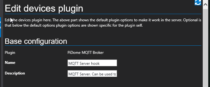
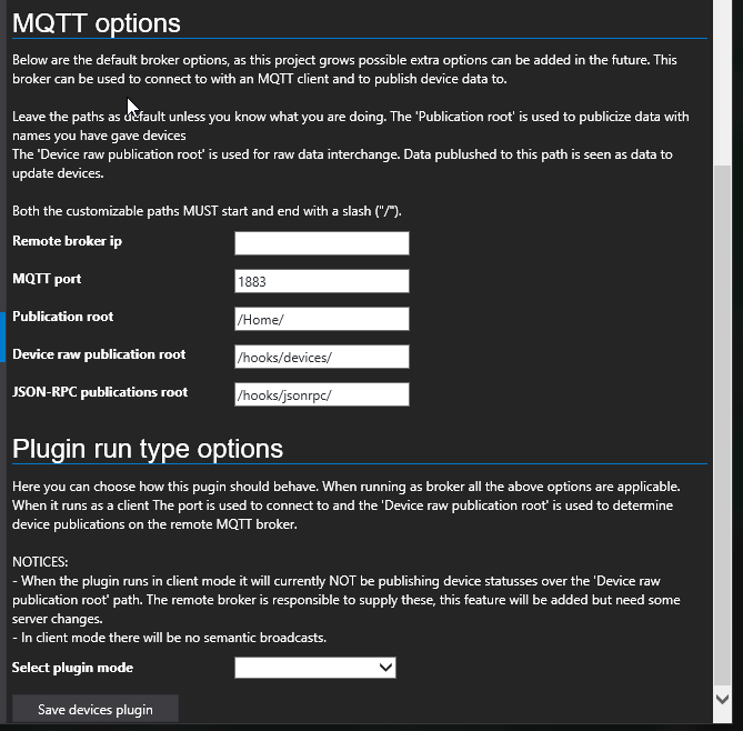
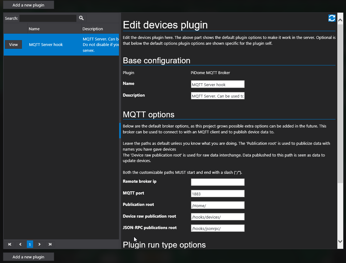
How to setup MQTT broker root ?
ARDUINO 1.6.8
MySENSORS ARDUINO LIBRARY V2.0.0-BETA
ARDUINO UNO R3 + W5100 ETHERNETSHIELD + NRF24L01 LONG RANGE
/**
 * The MySensors Arduino library handles the wireless radio link and protocol
 * between your home built sensors/actuators and HA controller of choice.
 * The sensors forms a self healing radio network with optional repeaters. Each
 * repeater and gateway builds a routing tables in EEPROM which keeps track of the
 * network topology allowing messages to be routed to nodes.
 *
 * Created by Henrik Ekblad <henrik.ekblad@mysensors.org>
 * Copyright (C) 2013-2015 Sensnology AB
 * Full contributor list: https://github.com/mysensors/Arduino/graphs/contributors
 *
 * Documentation: http://www.mysensors.org
 * Support Forum: http://forum.mysensors.org
 *
 * This program is free software; you can redistribute it and/or
 * modify it under the terms of the GNU General Public License
 * version 2 as published by the Free Software Foundation.
 *
 *******************************
 *
 * REVISION HISTORY
 * Version 1.0 - Henrik Ekblad
 *
 * DESCRIPTION
 * The W5100 MQTT gateway sends radio network (or locally attached sensors) data to your MQTT broker.
 * The node also listens to MY_MQTT_TOPIC_PREFIX and sends out those messages to the radio network
 *
 * LED purposes:
 * - To use the feature, uncomment WITH_LEDS_BLINKING in MyConfig.h
 * - RX (green) - blink fast on radio message recieved. In inclusion mode will blink fast only on presentation recieved
 * - TX (yellow) - blink fast on radio message transmitted. In inclusion mode will blink slowly
 * - ERR (red) - fast blink on error during transmission error or recieve crc error
 *
 * See http://www.mysensors.org/build/esp8266_gateway for wiring instructions.
 * nRF24L01+  ESP8266
 * VCC        VCC
 * CE         GPIO4
 * CSN/CS     GPIO15
 * SCK        GPIO14
 * MISO       GPIO12
 * MOSI       GPIO13
 *
 * Not all ESP8266 modules have all pins available on their external interface.
 * This code has been tested on an ESP-12 module.
 * The ESP8266 requires a certain pin configuration to download code, and another one to run code:
 * - Connect REST (reset) via 10K pullup resistor to VCC, and via switch to GND ('reset switch')
 * - Connect GPIO15 via 10K pulldown resistor to GND
 * - Connect CH_PD via 10K resistor to VCC
 * - Connect GPIO2 via 10K resistor to VCC
 * - Connect GPIO0 via 10K resistor to VCC, and via switch to GND ('bootload switch')
 *
  * Inclusion mode button:
 * - Connect GPIO5 via switch to GND ('inclusion switch')
 *
 * Hardware SHA204 signing is currently not supported!
 *
 * Make sure to fill in your ssid and WiFi password below for ssid & pass.
 */

#include <SPI.h>

// Enable debug prints to serial monitor
#define MY_DEBUG

// Enables and select radio type (if attached)
#define MY_RADIO_NRF24
//#define MY_RADIO_RFM69

#define MY_GATEWAY_MQTT_CLIENT

// Set this nodes subscripe and publish topic prefix
#define MY_MQTT_PUBLISH_TOPIC_PREFIX "mygateway1-out"
#define MY_MQTT_SUBSCRIBE_TOPIC_PREFIX "mygateway1-in"

// Set MQTT client id
#define MY_MQTT_CLIENT_ID "mysensors-1"

// W5100 Ethernet module SPI enable (optional if using a shield/module that manages SPI_EN signal)
//#define MY_W5100_SPI_EN 4

// Enable Soft SPI for NRF radio (note different radio wiring is required)
// The W5100 ethernet module seems to have a hard time co-operate with
// radio on the same spi bus.
#if !defined(MY_W5100_SPI_EN) && !defined(ARDUINO_ARCH_SAMD)
  #define MY_SOFTSPI
  #define MY_SOFT_SPI_SCK_PIN 14
  #define MY_SOFT_SPI_MISO_PIN 16
  #define MY_SOFT_SPI_MOSI_PIN 15
#endif

// When W5100 is connected we have to move CE/CSN pins for NRF radio
#define MY_RF24_CE_PIN 5
#define MY_RF24_CS_PIN 6

// Enable these if your MQTT broker requires usenrame/password
//#define MY_MQTT_USER "username"
//#define MY_MQTT_PASSWORD "password"

// Enable MY_IP_ADDRESS here if you want a static ip address (no DHCP)
#define MY_IP_ADDRESS 192,168,178,87

// If using static ip you need to define Gateway and Subnet address as well
#define MY_IP_GATEWAY_ADDRESS 192,168,178,1
#define MY_IP_SUBNET_ADDRESS 255,255,255,0

// MQTT broker ip address or url. Define one or the other.
//#define MY_CONTROLLER_URL_ADDRESS "m20.cloudmqtt.com"
#define MY_CONTROLLER_IP_ADDRESS 192, 168, 178, 68

// The MQTT broker port to to open
#define MY_PORT 1883

 /*
// Flash leds on rx/tx/err
#define MY_LEDS_BLINKING_FEATURE
// Set blinking period
#define MY_DEFAULT_LED_BLINK_PERIOD 300

// Enable inclusion mode
#define MY_INCLUSION_MODE_FEATURE
// Enable Inclusion mode button on gateway
#define MY_INCLUSION_BUTTON_FEATURE
// Set inclusion mode duration (in seconds)
#define MY_INCLUSION_MODE_DURATION 60
// Digital pin used for inclusion mode button
#define MY_INCLUSION_MODE_BUTTON_PIN  3

// Uncomment to override default HW configurations
//#define MY_DEFAULT_ERR_LED_PIN 16  // Error led pin
//#define MY_DEFAULT_RX_LED_PIN  16  // Receive led pin
//#define MY_DEFAULT_TX_LED_PIN  16  // the PCB, on board LED
*/

#include <Ethernet.h>
#include <MySensor.h>

void setup() {
}

void presentation() {
  // Present locally attached sensors here
}


void loop() {
  // Send locally attech sensors data here
}
ARDUINO NANO + NRF24L01
DallasTemperature Sensor
/**
 * The MySensors Arduino library handles the wireless radio link and protocol
 * between your home built sensors/actuators and HA controller of choice.
 * The sensors forms a self healing radio network with optional repeaters. Each
 * repeater and gateway builds a routing tables in EEPROM which keeps track of the
 * network topology allowing messages to be routed to nodes.
 *
 * Created by Henrik Ekblad <henrik.ekblad@mysensors.org>
 * Copyright (C) 2013-2015 Sensnology AB
 * Full contributor list: https://github.com/mysensors/Arduino/graphs/contributors
 *
 * Documentation: http://www.mysensors.org
 * Support Forum: http://forum.mysensors.org
 *
 * This program is free software; you can redistribute it and/or
 * modify it under the terms of the GNU General Public License
 * version 2 as published by the Free Software Foundation.
 *
 *******************************
 *
 * DESCRIPTION
 *
 * Example sketch showing how to send in DS1820B OneWire temperature readings back to the controller
 * http://www.mysensors.org/build/temp
 */

#include <MySensor.h>
#include <SPI.h>
#include <DallasTemperature.h>
#include <OneWire.h>
#include <MyHwATMega328.h>


#define COMPARE_TEMP 0 // Send temperature only if changed? 1 = Yes 0 = No

#define ONE_WIRE_BUS 3 // Pin where dallase sensor is connected
#define MAX_ATTACHED_DS18B20 16
#define RF24_CE_PIN 9 /*CE pin */
#define RF24_CS_PIN 10 /* CS pin, using 10  */
/* NRFRF24L01 radio driver (set high transmit power by default) */
MyTransportNRF24 radio(RF24_CE_PIN, RF24_CS_PIN, RF24_PA_LEVEL);

unsigned long SLEEP_TIME = 10000; // Sleep time between reads (in milliseconds)

MyHwATMega328 hw; /* Construct MySensors library */

OneWire oneWire(ONE_WIRE_BUS); // Setup a oneWire instance to communicate with any OneWire devices (not just Maxim/Dallas temperature ICs)
DallasTemperature sensors(&oneWire); // Pass the oneWire reference to Dallas Temperature.
MySensor gw(radio, hw); /* Construct MySensors library */
float lastTemperature[MAX_ATTACHED_DS18B20];
int numSensors=0;
int node_id = 30; /* set node ID here for manual */
boolean receivedConfig = false;
boolean metric = true;
// Initialize temperature message
MyMessage msg(0,V_TEMP);

void setup()
{
  // Startup up the OneWire library
  sensors.begin();
  // requestTemperatures() will not block current thread
  sensors.setWaitForConversion(false);

  // Startup and initialize MySensors library. Set callback for incoming messages.
  gw.begin(NULL,node_id);

  // Send the sketch version information to the gateway and Controller
  gw.sendSketchInfo("Temperature Sensor", "1.1");

  // Fetch the number of attached temperature sensors
  numSensors = sensors.getDeviceCount();

  // Present all sensors to controller
  for (int i=0; i<numSensors && i<MAX_ATTACHED_DS18B20; i++) {
     gw.present(i, S_TEMP);
  }
}


void loop()
{
  // Process incoming messages (like config from server)
  gw.process();

  // Fetch temperatures from Dallas sensors
  sensors.requestTemperatures();

  // query conversion time and sleep until conversion completed
  int16_t conversionTime = sensors.millisToWaitForConversion(sensors.getResolution());
  // sleep() call can be replaced by wait() call if node need to process incoming messages (or if node is repeater)
  gw.sleep(conversionTime);

  // Read temperatures and send them to controller
  for (int i=0; i<numSensors && i<MAX_ATTACHED_DS18B20; i++) {

    // Fetch and round temperature to one decimal
    float temperature = static_cast<float>(static_cast<int>((gw.getConfig().isMetric?sensors.getTempCByIndex(i):sensors.getTempFByIndex(i)) * 10.)) / 10.;

    // Only send data if temperature has changed and no error
    #if COMPARE_TEMP == 1
    if (lastTemperature[i] != temperature && temperature != -127.00 && temperature != 85.00) {
    #else
    if (temperature != -127.00 && temperature != 85.00) {
    #endif

      // Send in the new temperature
      gw.send(msg.setSensor(i).set(temperature,1));
      // Save new temperatures for next compare
      lastTemperature[i]=temperature;
    }
  }
  gw.sleep(SLEEP_TIME);
}```
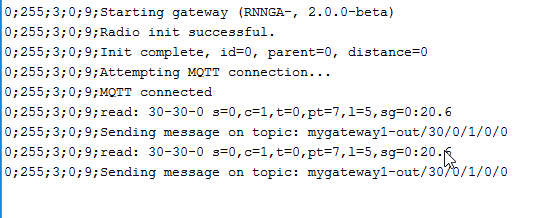
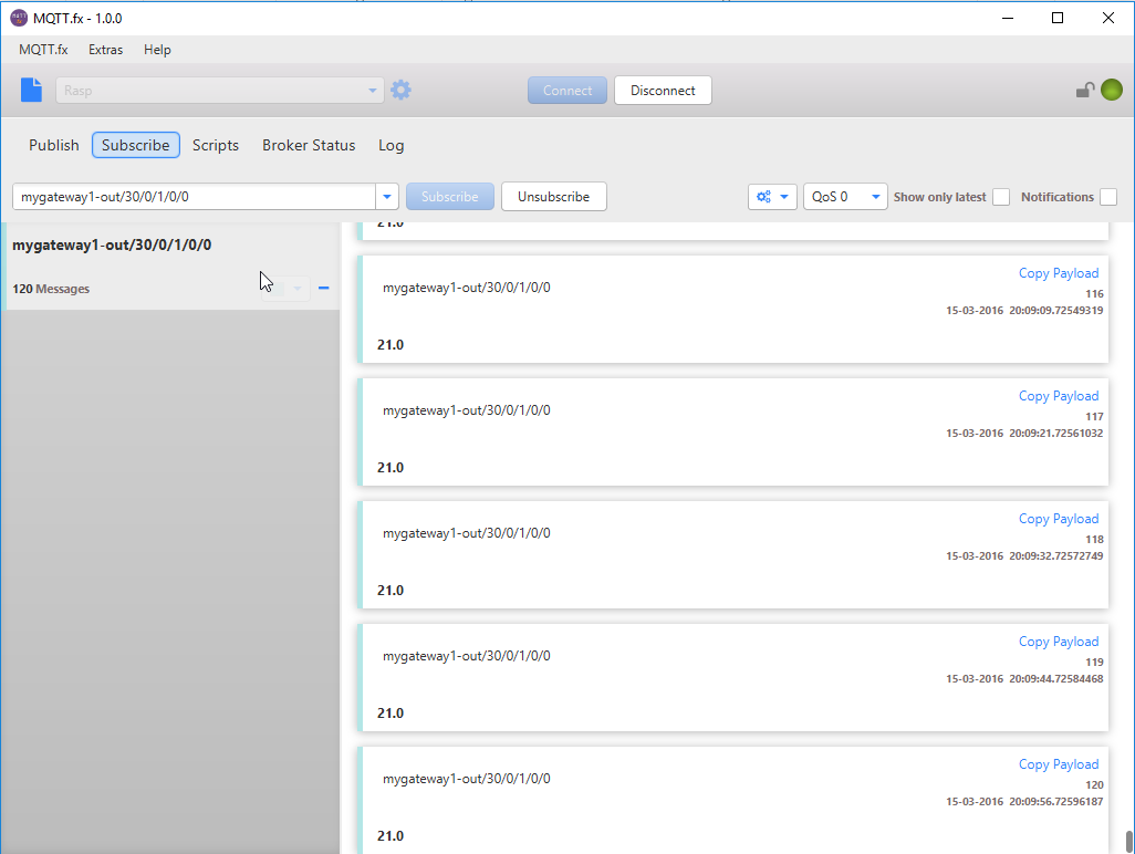
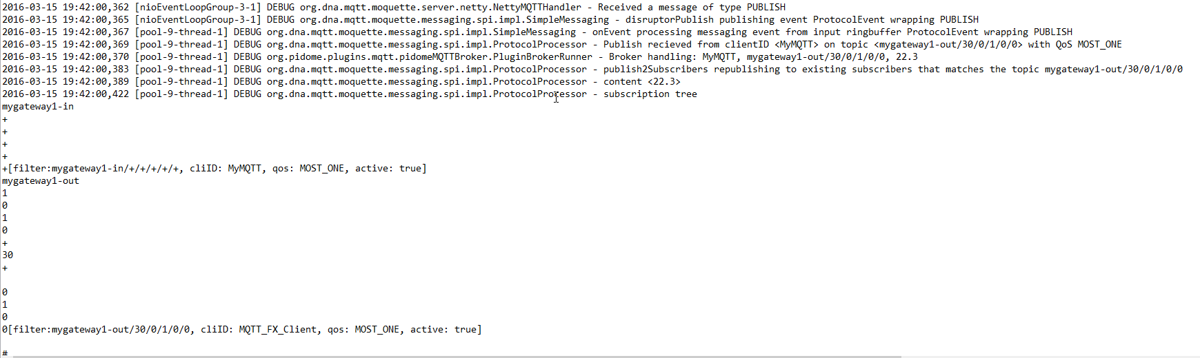
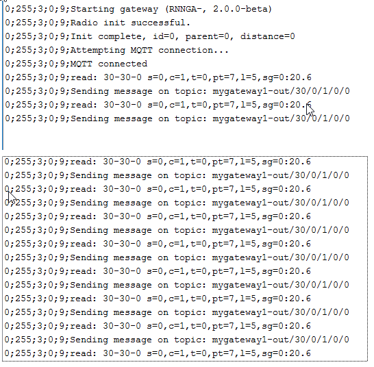
Serial log MQTTgateway
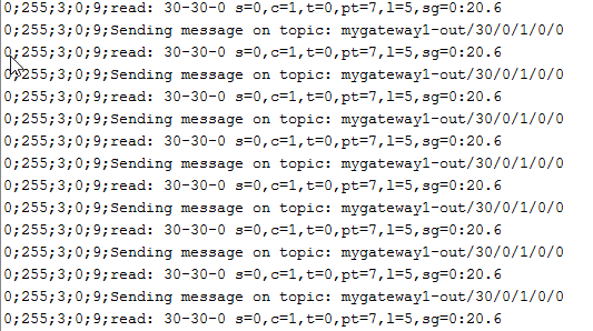
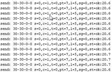
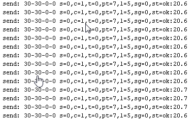
Serial log sensor
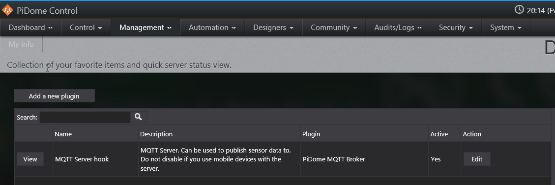
Pidome