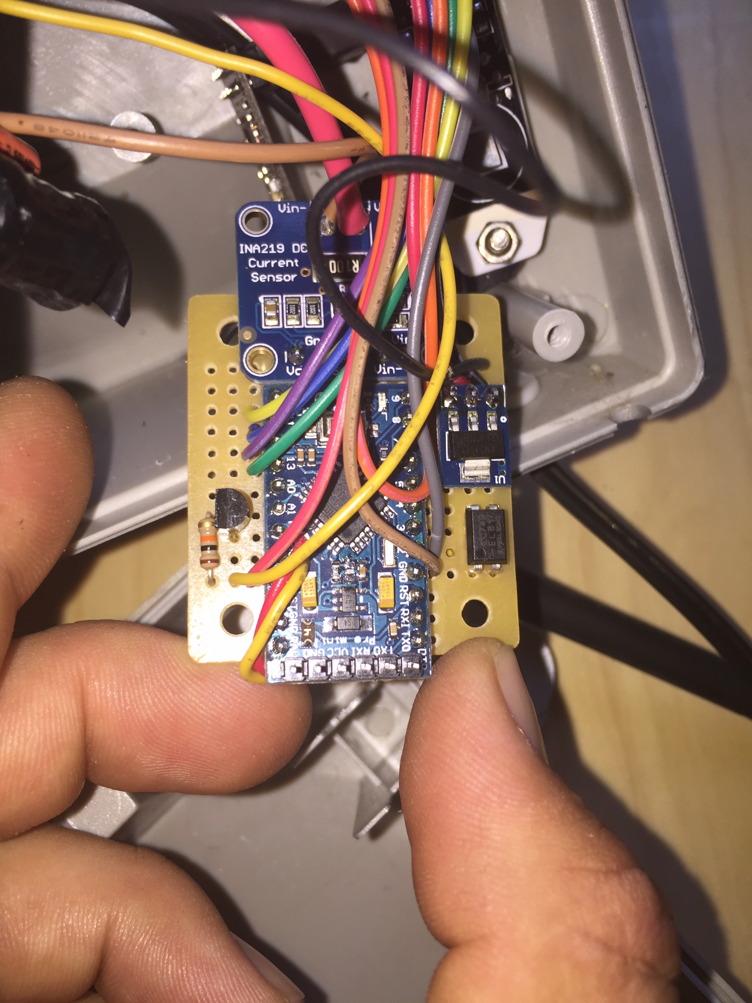
@Dwalt I used a general purpose BC547B transistor. The voltage drop was too low to use this alone so thats why I added a pc817 optoisolator as well! Im not very savvy with these kinds of circuits, but what I did is wire the signal source to a 10k resistor then to base. Vcc to 270ohm resistor into optoisolator then out to collector. Emitter to common ground. Don't forget the 10k pull down on the optoisolator output! In your case the wiring will be slightly different since your triggered signal is the inverse of mine!
HighSierraJoe
Posts
-
Solar powered LED motion activated light with MySensors upgrade -
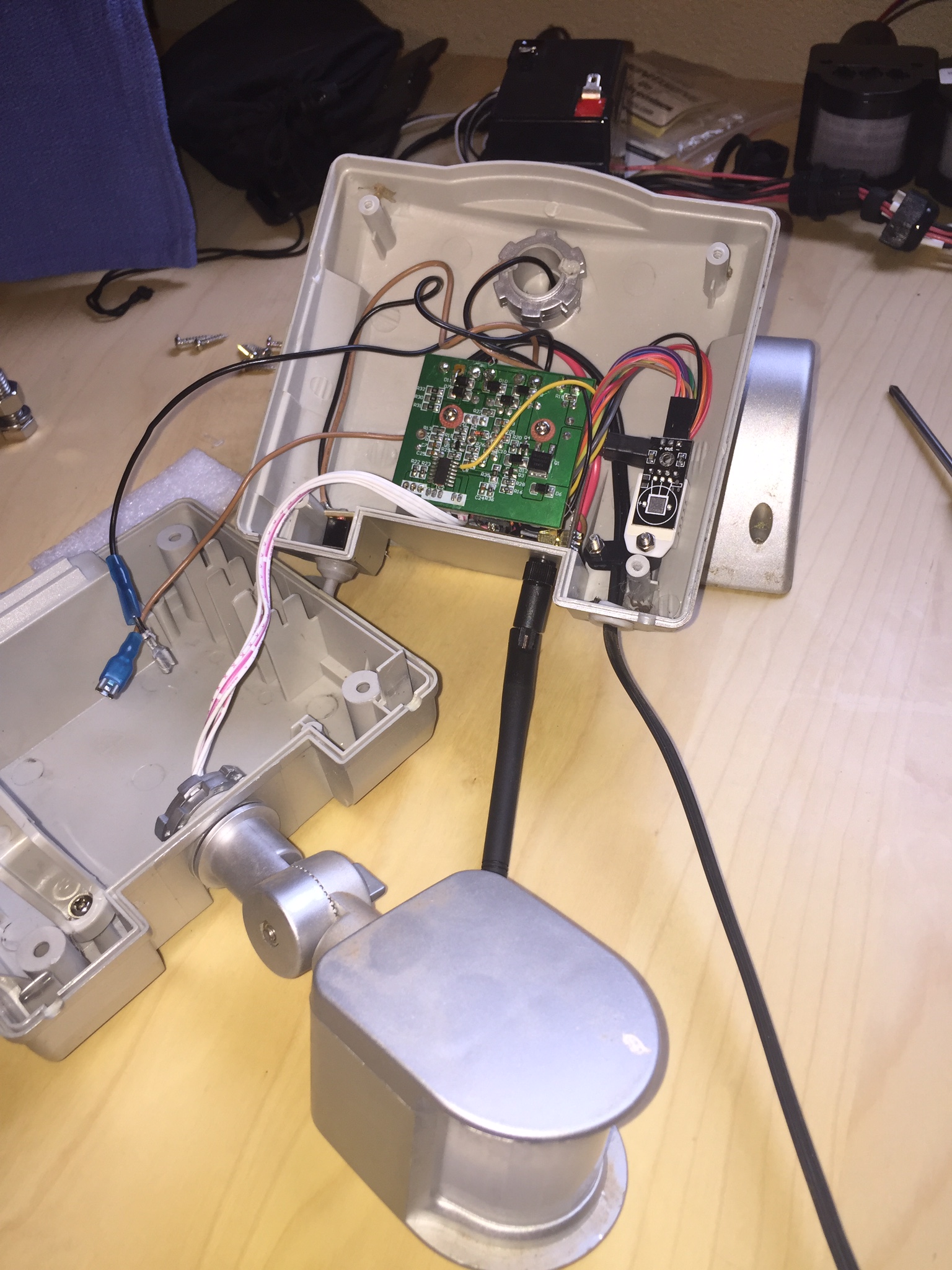
Solar powered LED motion activated light with MySensors upgrade@Dwalt I could not find the model of the chip as there is nothing printed on top of it, so I had to use my fluke and check each pin until I found the output signal. You can see in the bottom picture I soldered the yellow wire onto pin 13. Then as I mentioned earlier the signal voltage output was only 2.6 volts, right around the threshold for digital input detection, so when motion was triggered my readings were erratic. To fix this I had to build a simple transistor and optoisolator circuit to up convert the signal to 3.3 volts and satisfy the pro mini when detecting the motion trigger signal.
-
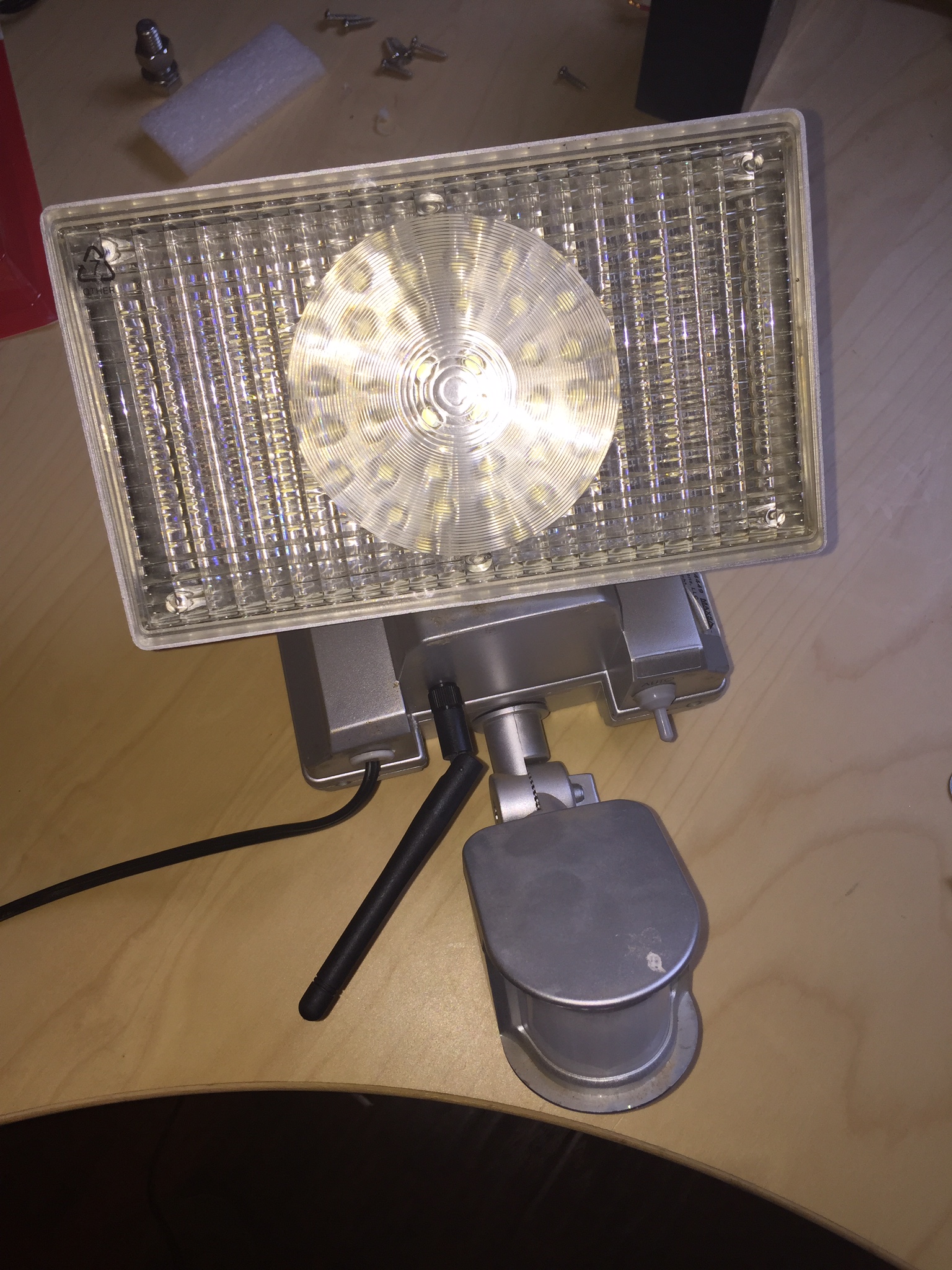
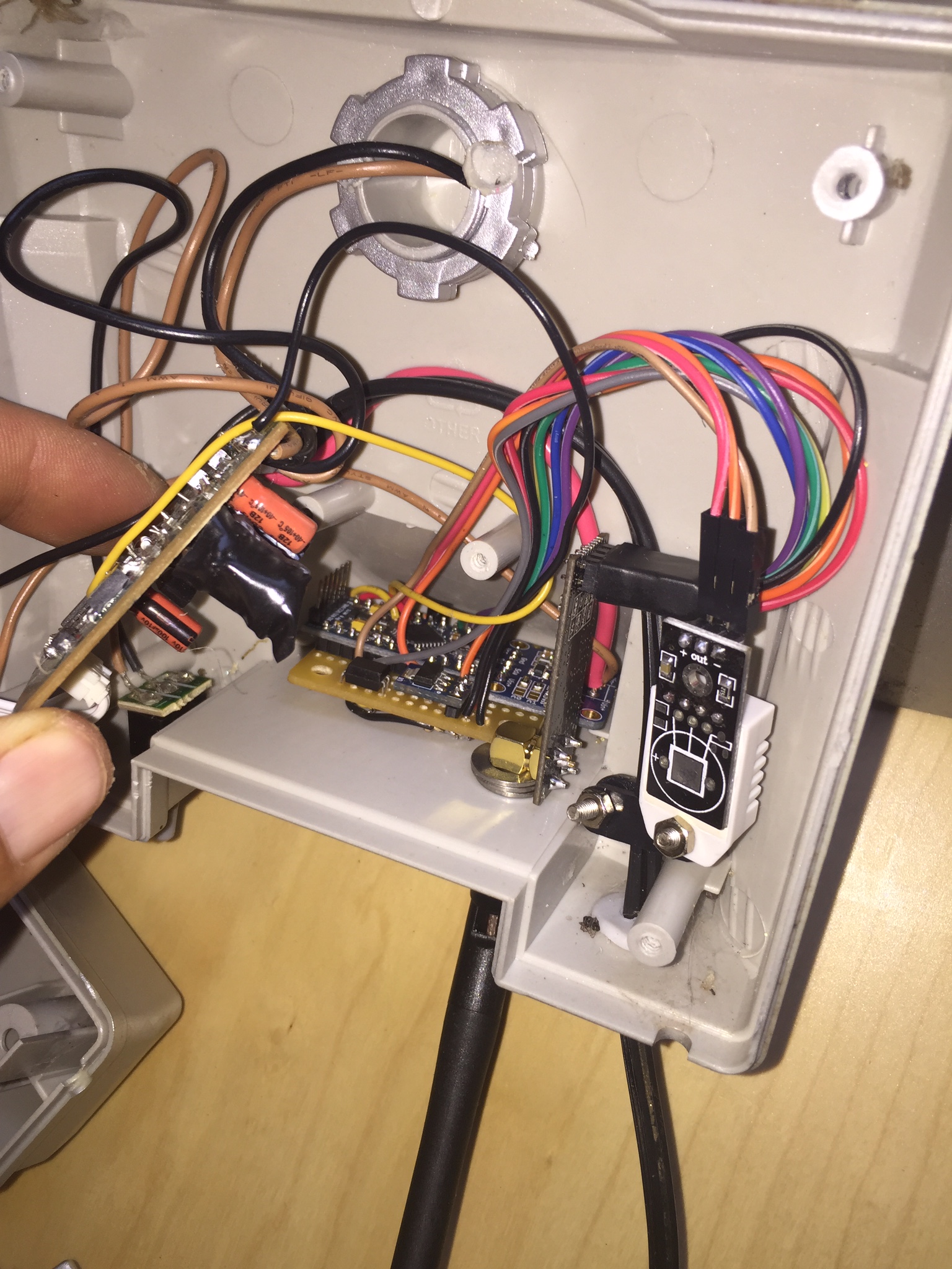
Solar powered LED motion activated light with MySensors upgradeI would like to share a recent project I did where I modified my Motion activated MAXSA 44449-L Silver 100-LED Solar-Powered Security Floodlight to include a nice MySensor upgrade! I used the 3.3v pro-mini and the NRF24L01+PA+LNA antenna version because of the 300m distance from the gateway. To my surprise it all fit perfectly well inside the existing chassis without modification besides the hole I had to drill for the antenna! It's been working great and running for about 3 weeks now without a glitch and graphing all sensors on Domoticz.
During the build and testing phase I ran into problem when sensing the motion output as the motion trigger output voltage only runs at 2.6 volts causing a very erratic detection with the pro mini digital input. So I had to build a simple transistor and optoisolator circuit to step up the output trigger voltage to 3.3 volts.
Features I included:
-sends back motion trigger status (most important!)
-sends temp and humidity using DHT22 probe(why not?)
-sends battery and watt usage including what comes in from the included solar panel during the day using the adafruit ina219 breakout board!


-
INA219 DC Current SensorThanks for the replies!
@hek
I added the 2 new variables as you suggested. I already hacked the power device so the values are being displayed in the proper amps and volts, but having a hard time getting notifications to work properly! So with that being said you have my vote as well to include this in 1.4 as its own device showing DC volts and amps or even converted to watts is acceptable.These split core CT's look pretty nice. They could make a cheap replacement to other energy monitors like TED5000 and would take up less room in your panel if you can tie multiple CT pairs into one wireless sensor node.
-
INA219 DC Current SensorI am new to the MySensors.org community but I have been having a blast building all types of wireless sensors since a first discovered this site a few weeks ago and would love be be able to contribute to this community!
The INA219 Current Sensor Breakout Board by Adafruit is a great little sensor for measuring current and voltages, up to 3.2 amps and 26 volts quite accurately! https://www.adafruit.com/products/904. It uses i2c to send its data and there is a nice library to go along with it. With a simple modification you can change the shunt resistor out to lower values measure higher currents or in my case I remove it completely so I can measure the current across a 500 amp shunt. Im using this sensor to monitor my camping trailer's battery voltage and current draw while it is parked. I also use it to monitor my auxiliary battery backup system that keeps my security camera server and wifi router running in case of a power failure. Ive been using an arduino web server running ajax script so I can monitor my battery systems remotely in real time.
It is most important for me to monitor my trailer batteries since I have spent hundreds of dollars on AGM batteries and would like to be alerted if for some reason the breaker to the trickle charger tripped or the charger malfunctioned and something was left on in the trailer that could draw the batteries down to dead! AGM batteries can only go dead just a few time before there no good.
I have wired the INA219 sensor into a sensor node, but since unfortunately there is no sensor type to associate with this particular sensor I have chosen to use the most related S_POWER sensor type and Power Meter device in my Vera3 and use the 2 variables (V_WATT, V_KWH) to send the voltage and current data over. I have even modified the JSON file in Vera3 so that the device label can read volts and current instead of the original watts and KWH. And also added in a couple of new notifications so that i can be alerted if the voltage drops below 12.6 volts or if current draw goes below 0.
It has been working for the time being, but this is quite a hack job and it would be great if there was a better and nicer way! It looks to me like this idea requires a whole new device to be added to the MySensors plugin and the corresponding variables added to sensors.h? Can someone help point me in the right direction with this? Maybe there are others out there that would be as interested in this project as I am! :)
