Navigation

    • Register
    • Login
    • OpenHardware.io
    • Categories
    • Recent
    • Tags
    • Popular
    1. Home
    2. phil83
    3. Posts
    • Profile
    • Following
    • Followers
    • Topics
    • Posts
    • Best
    • Groups

    Posts made by phil83

    • RE: Yet another PCB to address (nearly) all Arduino pins

      I finally went on with the project and received the pcbs last week... my soldering oven is running and I could finish the first board (still some parts are missing 😞 ) If only I had more time to work on that...
      Here are some impressions:

      0_1462218235982_IMG_0774.JPG
      I soldered some cables so that I can program it and check via ftdi...

      0_1462218348535_IMG_0775.JPG

      0_1462218430167_IMG_0780.JPG

      More to come soon...

      posted in Hardware
      phil83
      phil83
    • RE: Yet another PCB to address (nearly) all Arduino pins

      As I read your post again, you mean something like this:
      http://de.aliexpress.com/item/5-sets-Double-Row-Female-Socket-SMD-2-10-20pin-1-27mm-Pin-Header-connector/32542921161.html?isOrigTitle=true

      posted in Hardware
      phil83
      phil83
    • RE: Yet another PCB to address (nearly) all Arduino pins

      @GertSanders: On aliexpress you can find sets of male and female 1.25mm connectors, do you think about something like that:
      http://de.aliexpress.com/item/20sets-Micro-1-25mm-5pin-Cable-JST-1-25-5-Pin-Male-Female-Connector-plug-with/32464250609.html?spm=2114.010208.3.2.BMcTZF&ws_ab_test=searchweb201556_9,searchweb201644_5_505_506_503_504_301_10020_502_10001_10002_10017_10010_10005_10006_10011_10003_10021_10004_10022_10009_10008_10018_10019,searchweb201560_2,searchweb1451318400_-1,searchweb1451318411_6448&btsid=8ded8c25-db33-49ed-835b-307cb83c0f47

      posted in Hardware
      phil83
      phil83
    • RE: Yet another PCB to address (nearly) all Arduino pins

      @tbowmo: Sounds very impressive, chapeau! I'm looking forward to seeing your design when it is finished!

      posted in Hardware
      phil83
      phil83
    • RE: Yet another PCB to address (nearly) all Arduino pins

      @TD22057: My dealer in China does some panelization for me as well, last time I ordered 20 board (size about 25x45mm) and I received 42... That was more than fine for me. But thanks for the link!

      posted in Hardware
      phil83
      phil83
    • RE: Yet another PCB to address (nearly) all Arduino pins

      Hi all,
      many thanks for all the valuable input!
      I will share my files after having tested the board by myself for the first time!

      @GertSanders: I've never thought about using the SMD version of NRF24L01, it really looks interesting!

      @tbowmo: Your board size is really impressive, are you also using the EEPROM and ATSHA on that small size board?

      The smallest and still (hopefully) manufacturable for me seems to be around 44x21mm...
      0_1456693207843_micro sensor v1.1.png
      Right now I'm waiting for all of the parts of my reflow oven, I have some boards for testing here and in case I'm successful with reflowing, I will order new boards in China.

      Best regards,
      Philipp

      posted in Hardware
      phil83
      phil83
    • RE: Yet another PCB to address (nearly) all Arduino pins

      Hi TD,
      many thanks for the library, I incorporated the drill holes and it looks much better now!

      0_1456571043915_mini sensor v6.2.png

      Best regards,
      Philipp

      posted in Hardware
      phil83
      phil83
    • RE: Yet another PCB to address (nearly) all Arduino pins

      Hi there,

      I had some more time to work on it and I rearranged the parts on the board. One question for me is how big to make the drill holes for mounting? Is 2mm ok?

      0_1456510649033_v6.1.png
      0_1456510664572_v6.1scheme.png

      I will clean up the silk screen writings the weekend and then send it out to China 🙂

      Many thanks so far,
      best regards,
      Philipp

      posted in Hardware
      phil83
      phil83
    • RE: Yet another PCB to address (nearly) all Arduino pins

      Regarding the MYSX connector, I have seen the specification before but for me the 2.54mm pinheads are way to big since I wanted to have a really small board that I can also use for quite small sensors (window open for example). I changed some connections and came up with that scheme now:
      0_1456052963816_mini sensor v6.png

      I added the caps for the ICs, many thanks again for the hint!
      Philipp

      posted in Hardware
      phil83
      phil83
    • RE: Yet another PCB to address (nearly) all Arduino pins

      So this could be an updates pin assignment:

      Arduino Pin/ Function/ Pinhead
      0/ RXI/ not used
      1/ TXO/ not used
      2/ D2/ NRF24 / Pinhead 1 / Button (via jumper)
      3/ D3/ Pinhead 1
      4/ D4/ Pinhead 2
      5/ D5/ Pinhead ISP
      6/ D6/ LED
      7/ D7/ LED
      8/ D8/ 25AA256
      9/ D9/ NRF24
      10/ D10/ NRF24
      11/ MOSI/ Pinhead ISP
      12/ MISO/ Pinhead ISP
      13/ SCK/ Pinhead ISP
      A0/ A0/ Voltage divider
      A1/ A1/ Dallas 18B20
      A2/ A2/ Pinhead 2
      A3/ A3/ Pinhead ISP
      A4/ SDA/ Pinhead I2C
      A5/ SCL/ Pinhead I2C
      A6/ A6/ Pinhead 2
      A7/ A7/ Pinhead 1

      What do you think?
      Best regards,
      Philipp

      posted in Hardware
      phil83
      phil83
    • RE: Yet another PCB to address (nearly) all Arduino pins

      Hey guys,

      many thanks so far, I will incorporate TD's ideas tomorrow.
      For the A7, many thanks to Gert! Only A0-A5 can be used as digital pins so I will change this!
      Design rule check was fine.

      Thanks again and have a nice evening,
      Philipp

      posted in Hardware
      phil83
      phil83
    • Yet another PCB to address (nearly) all Arduino pins

      Hi everyone,

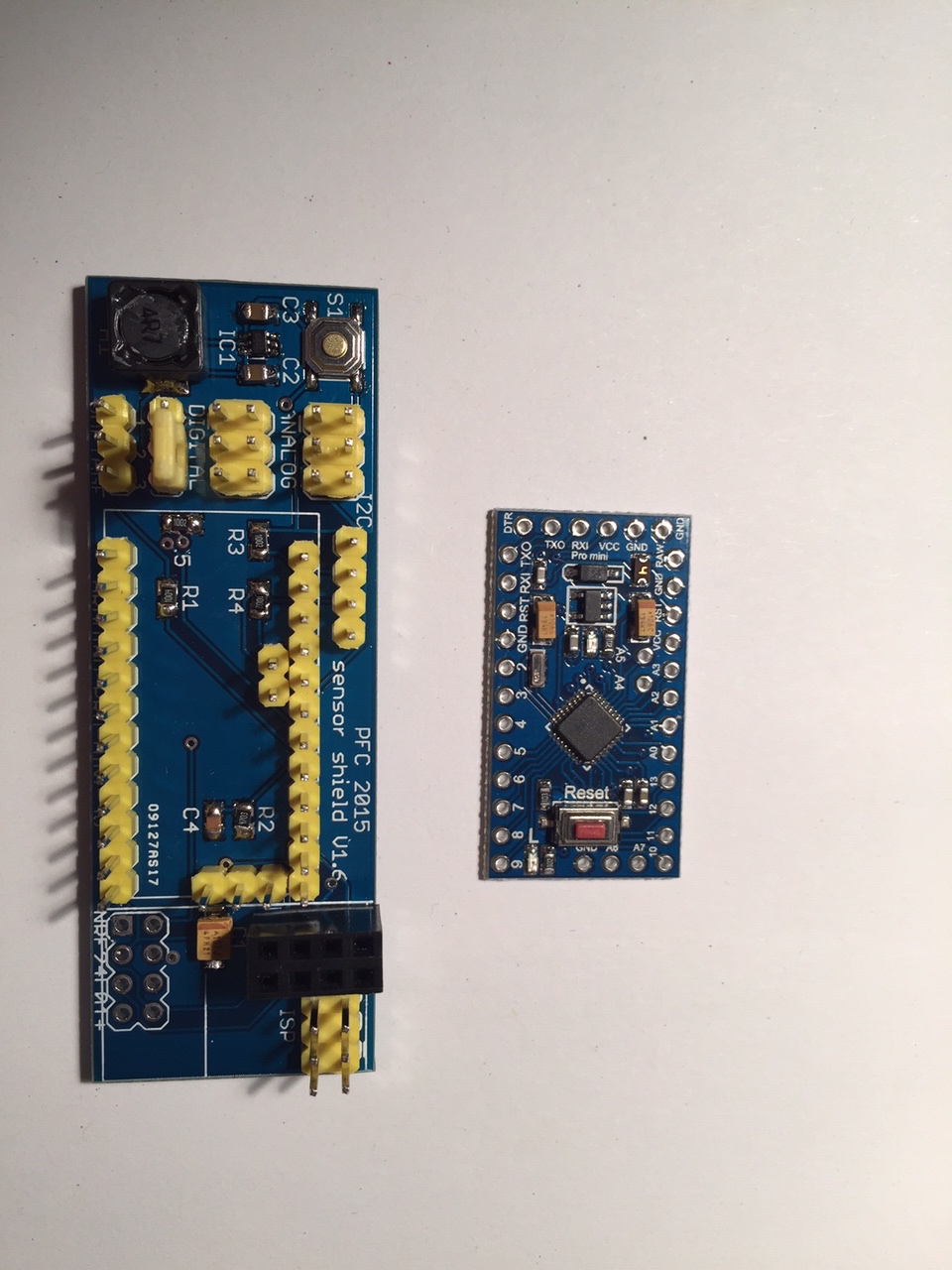
      after I had my first PCB manufactured last year in China, I'm a little bit addicted to designing and soldering new boards so here's another idea for a universal board. I'm building my own reflow oven right now, so I will try to directly use smt parts without using an arduino pro mini on top of my board.

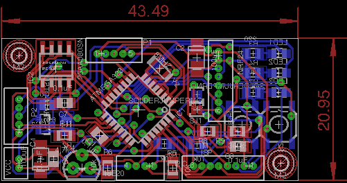
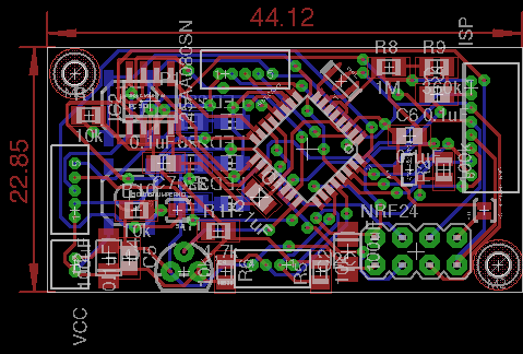
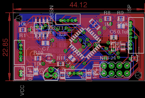
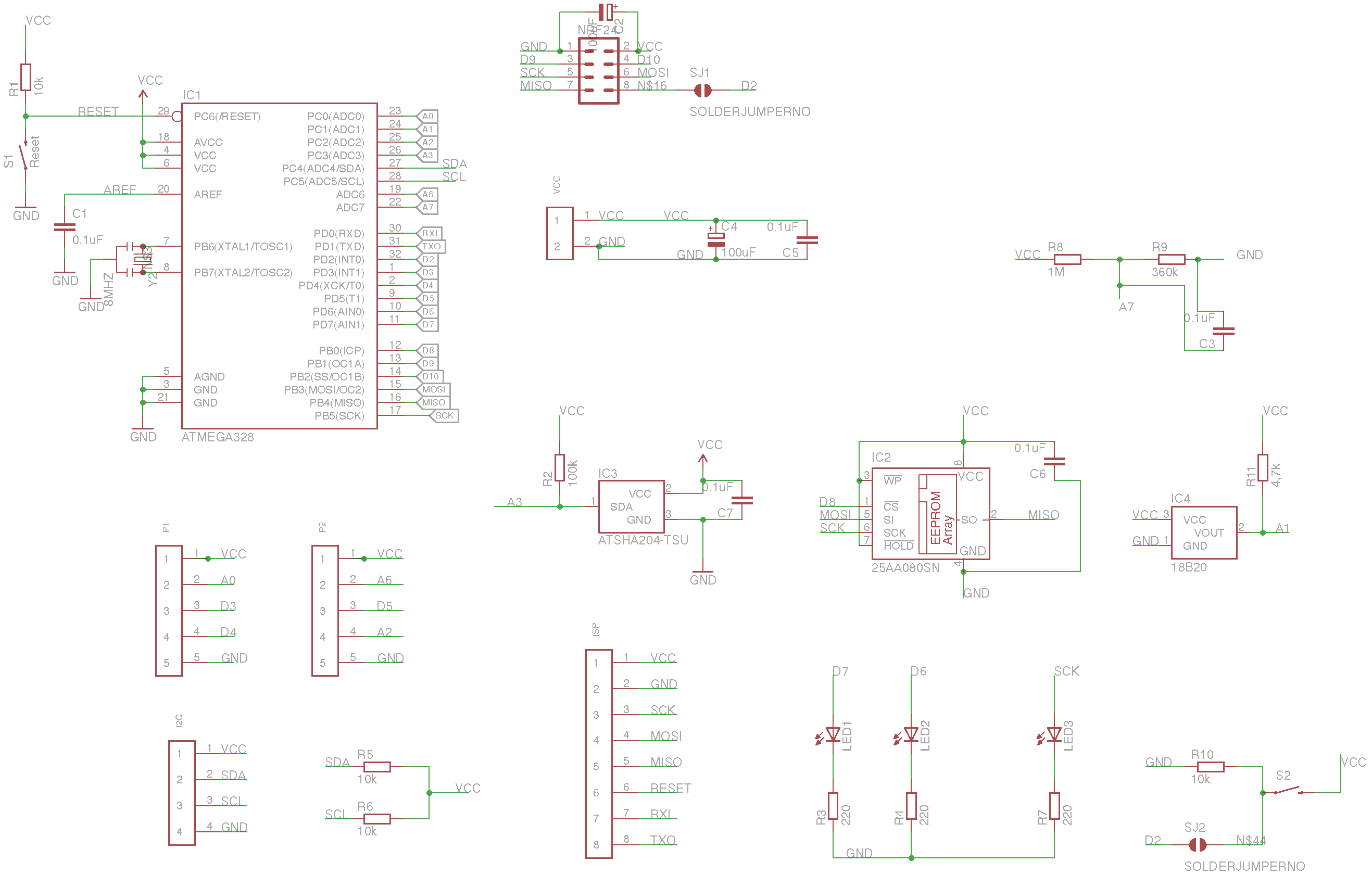
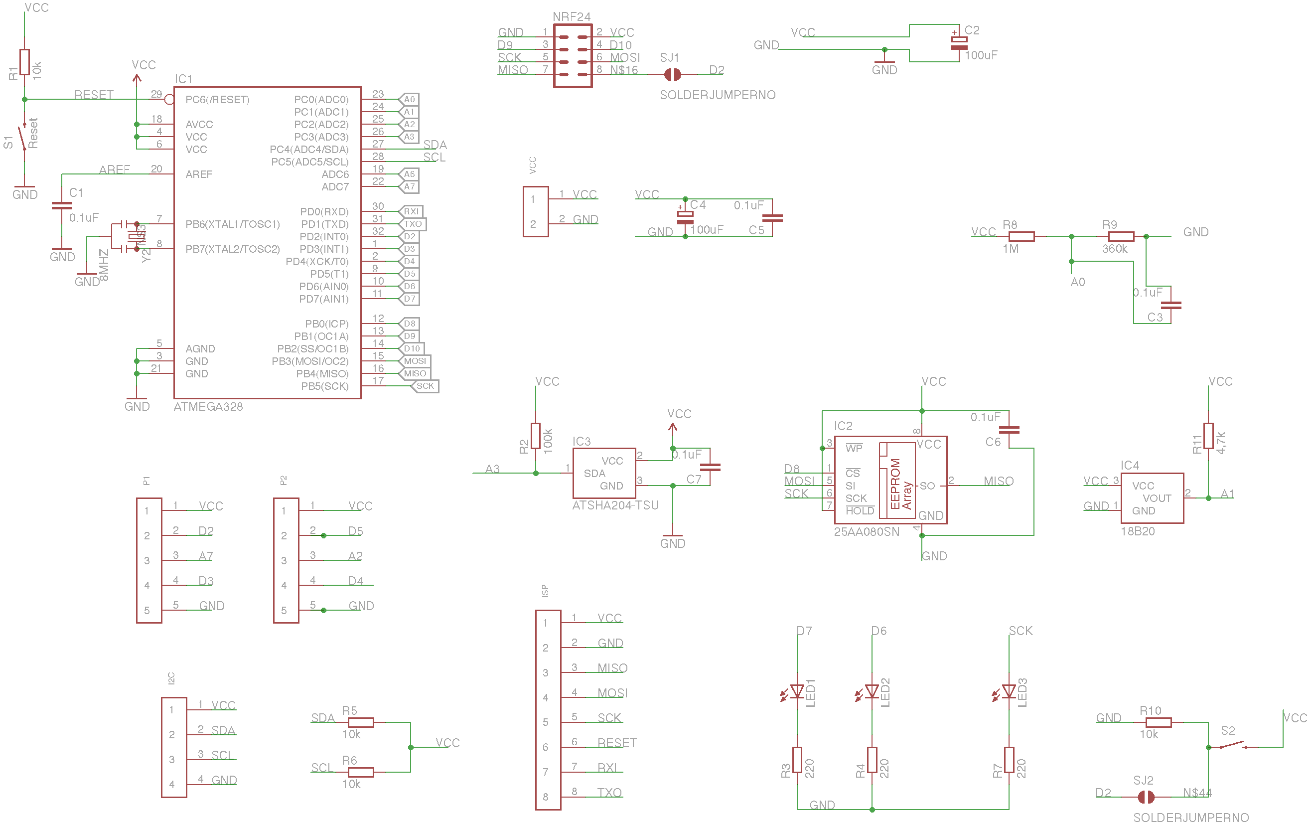
      The scheme looks like this:
      0_1455989457737_mini Sensor V6.png

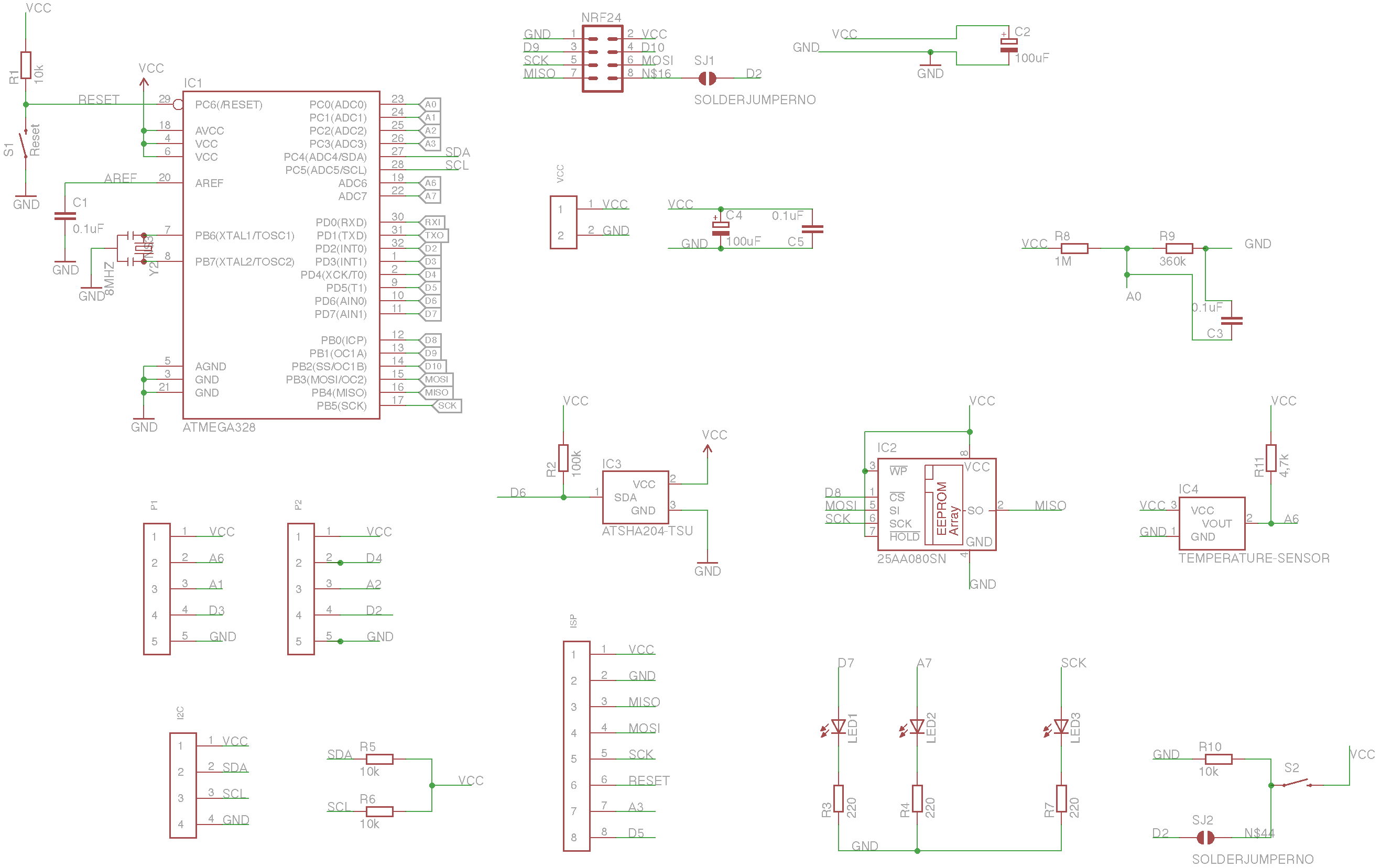
      I added as many parts as possible and tried to make nearly all other pins for Arduino accessible with some 1.25mm pinheads. Here's a list of all the pins and where you'll find them:

      Arduino Pin/ Function/ Pinhead
      0/ RXI/ not used
      1/ TXO/ not used
      2/ D2/ NRF24 / Pinhead 2 / Button (via jumper)
      3/ D3/ Pinhead 1
      4/ D4/ Pinhead 2
      5/ D5/ Pinhead ISP
      6/ D6/ ATSHA
      7/ D7/ LED
      8/ D8/ 25AA256
      9/ D9/ NRF24
      10/ D10/ NRF24
      11/ MOSI/ Pinhead ISP
      12/ MISO/ Pinhead ISP
      13/ SCK/ Pinhead ISP
      A0/ A0/ Voltage divider
      A1/ A1/ Pinhead 1
      A2/ A2/ Pinhead 2
      A3/ A3/ Pinhead ISP
      A4/ SDA/ Pinhead I2C
      A5/ SCL/ Pinhead I2C
      A6/ A6/ Dallas 14B20
      A7/ A7/ LED

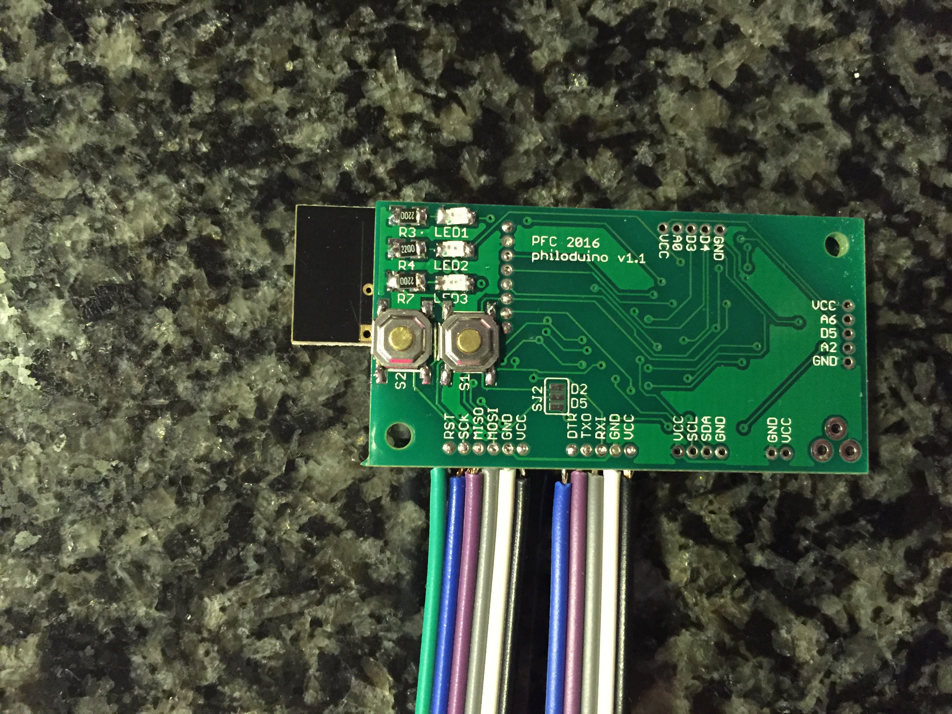
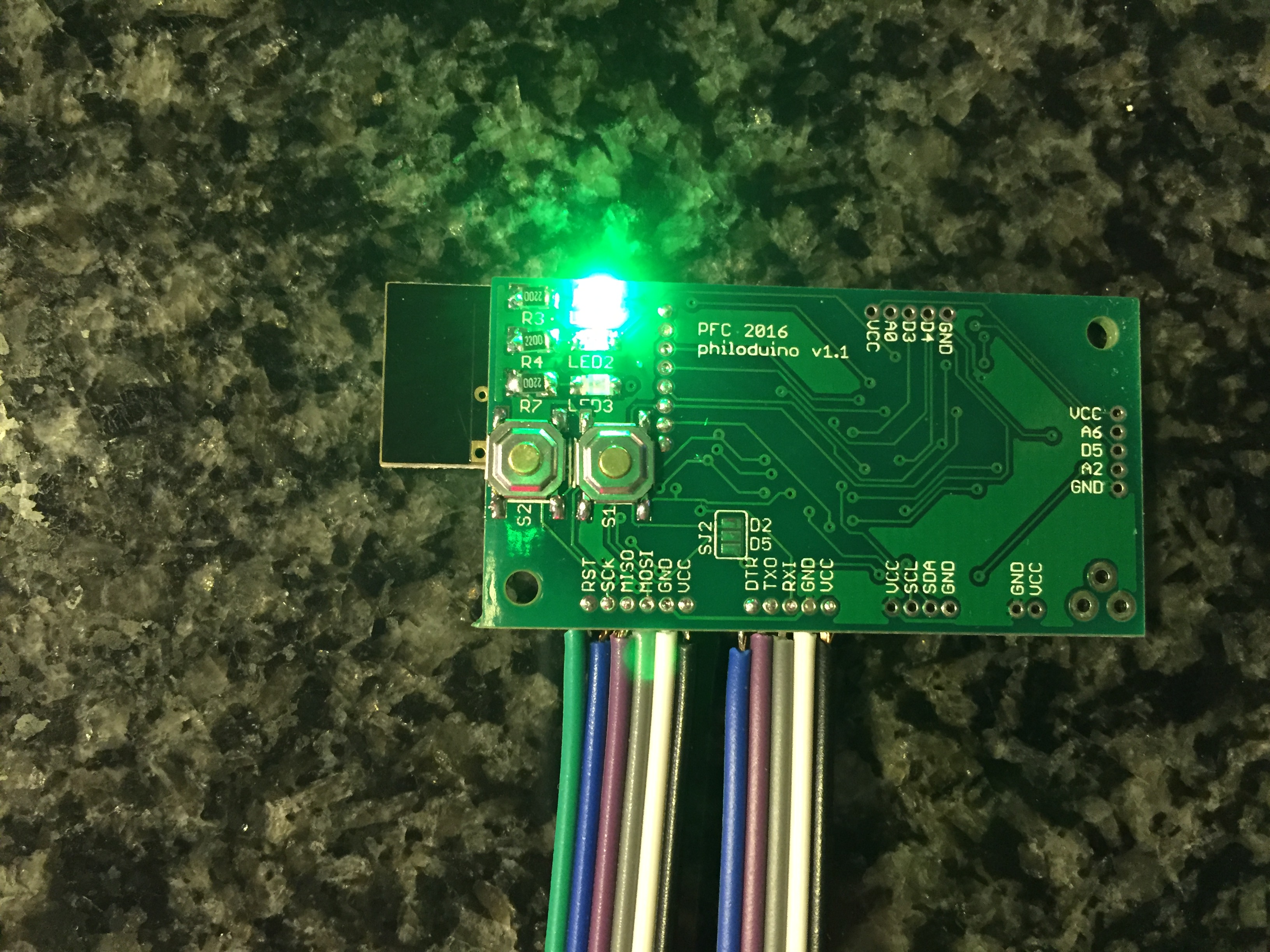
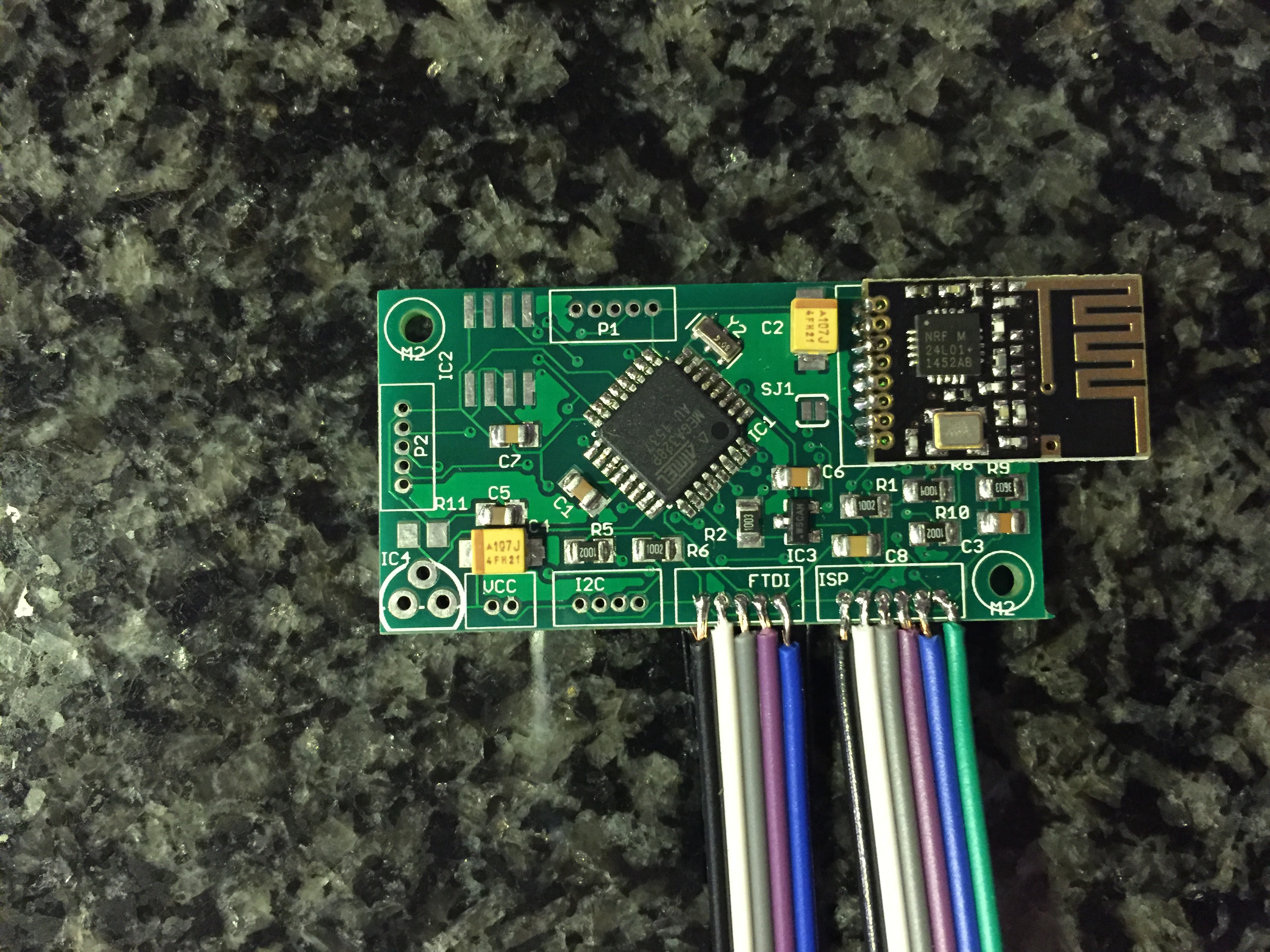
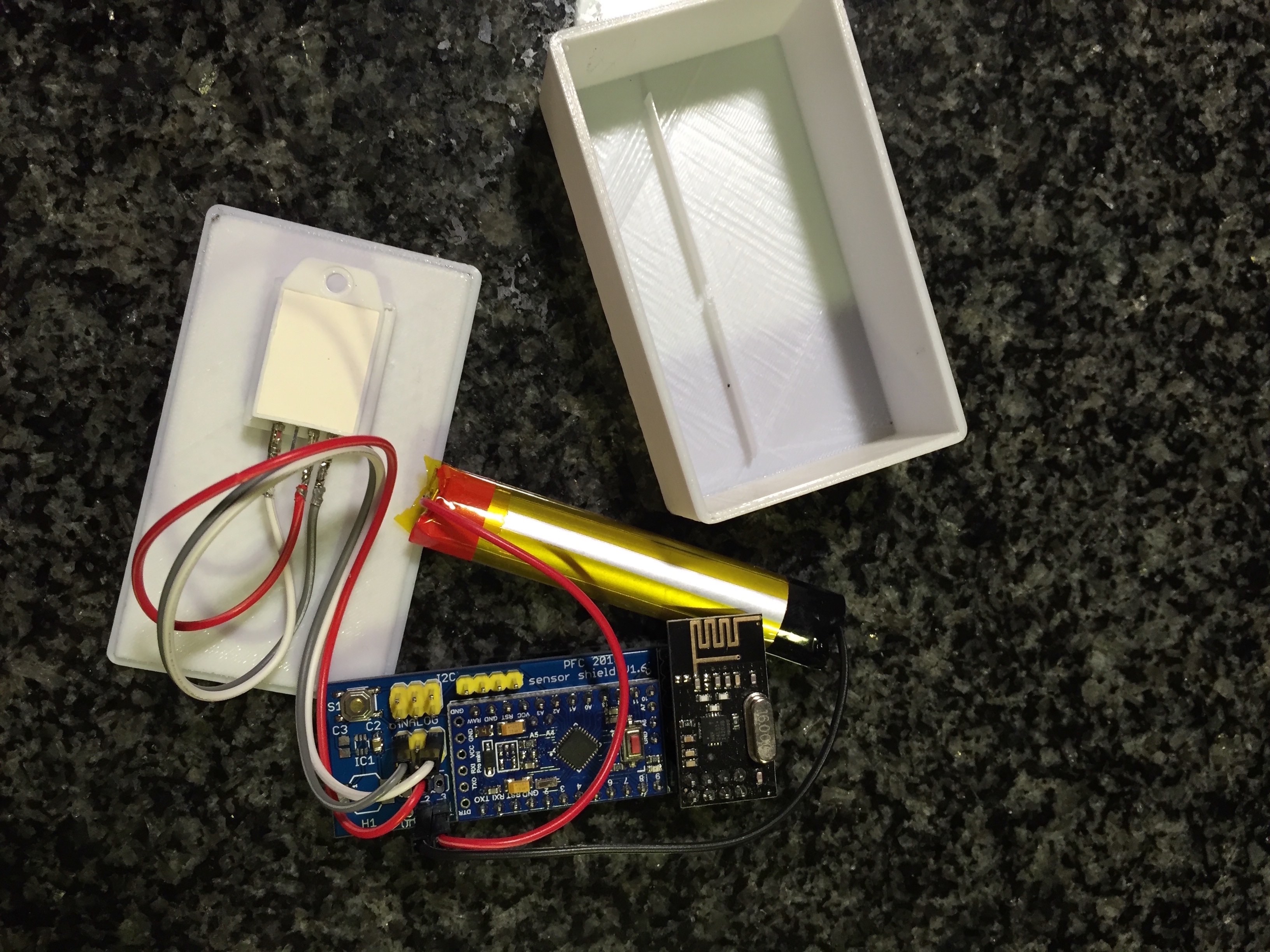
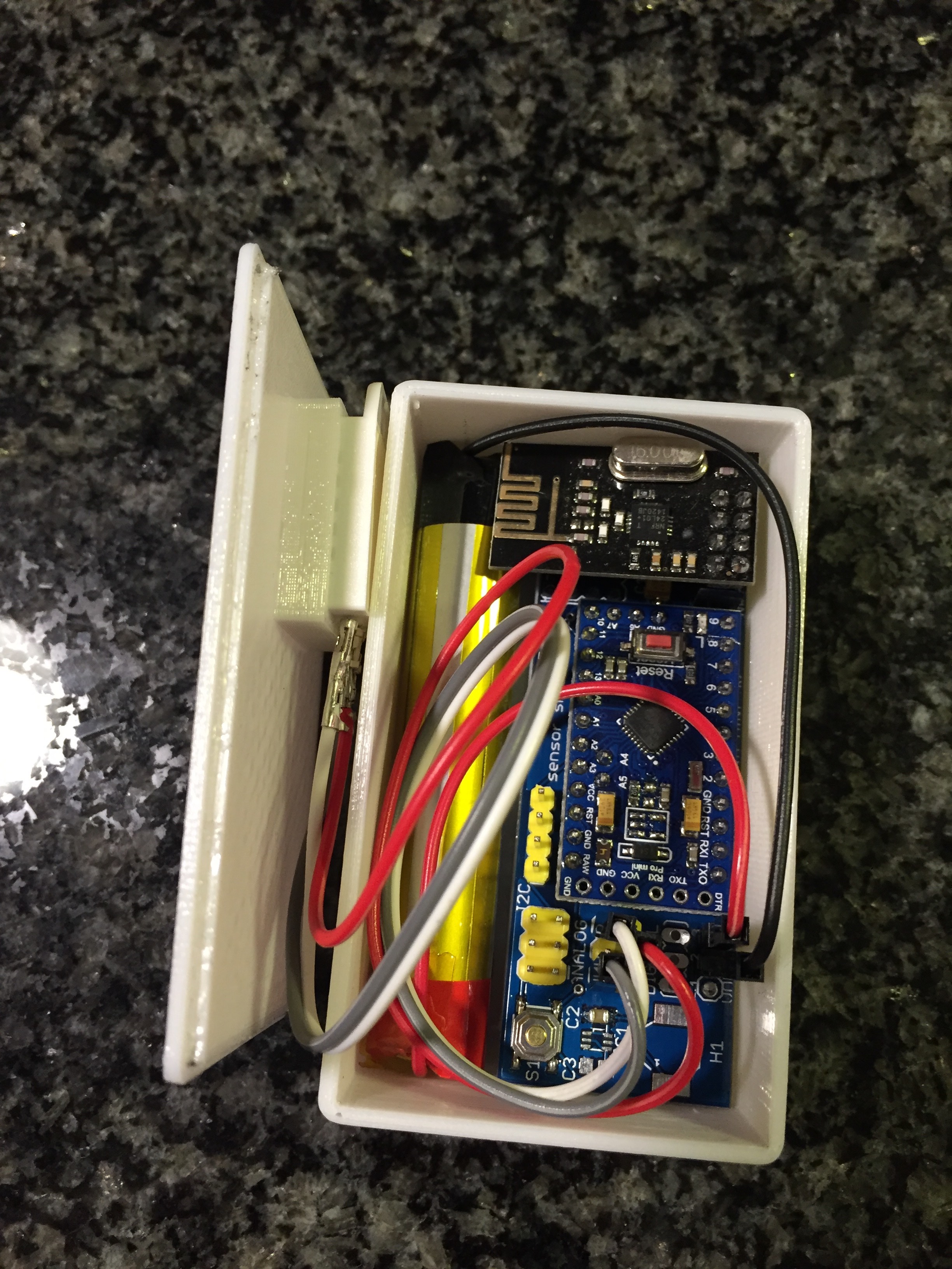
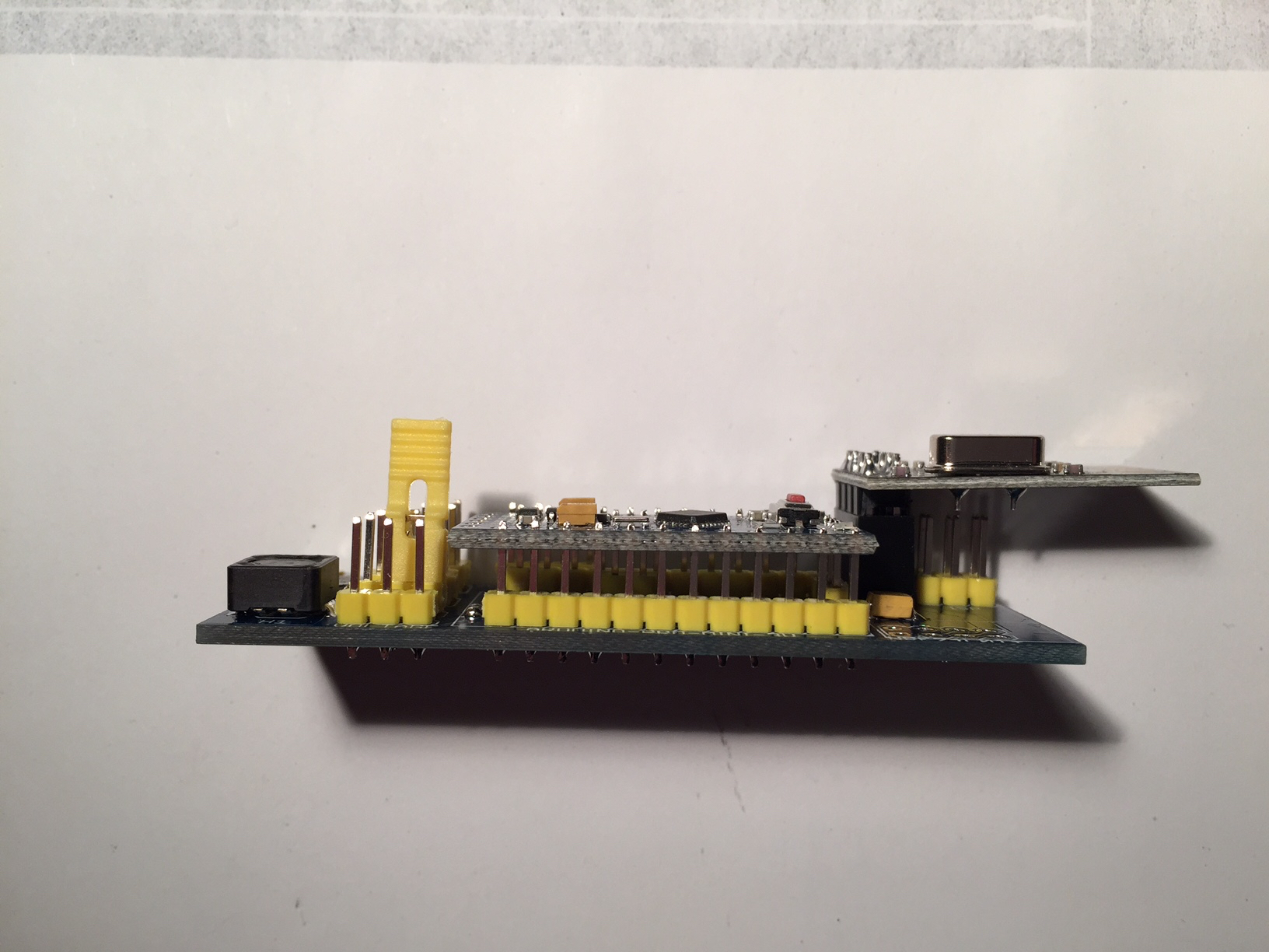
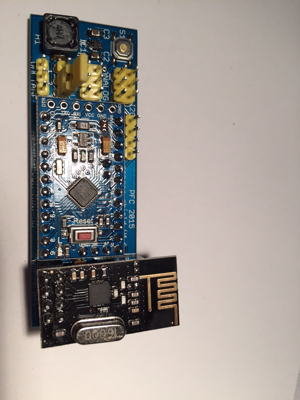
      On the front of the board, there's the Atmega, an ATSHA, an EEPROM and a D18B20. on the back, I have two tactile switches and 3 LEDs, the idea is to drill holes in the box and access them from the bottom side while the additional sensors will be in front of the Atmega chip. Besides the ISP head for programming, I added some more digital lines to the ISP pinhead so the pinhead can also being used to connect to another serial device (with the digital pins being CS lines).
      There are two connectors for connection to sensors etc and an I2C connector.
      0_1455990141375_mini sensor V6 board.png

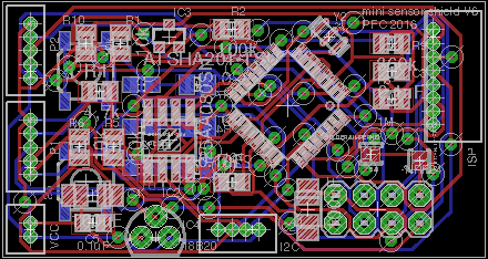
      Size of the board would be 44.1x23.5mm.

      What do you think of this layout? Is there any wrong connection regarding Arduino pins? Any ideas to improve the layout?

      Many thanks for your input in advance,
      best regards,
      Philipp

      posted in Hardware
      phil83
      phil83
    • RE: Sensor shield for Arduino Pro Mini 3.3V with boost up regulator

      Long time no see... I had time to work on my sensors lately and here are some pictures of my humidity sensor which is running here for three months now:

      0_1454090300302_IMG_00061.jpg
      0_1454090355121_IMG_00041.jpg
      0_1454090545068_IMG_00031.jpg

      I left out the power regulator shown above and also desoldered the LED and voltage regulator of the Arduino to safe power. The sensor is directly powered by 3.7V of the lithium battery. The voltage is measured and the battery will be recharged when it goes down.
      Since I also built a 3D printer lately, I was able to put the sensor into a little box. Now I can easily measure humidity and temperature in my bath room and see it in fhem on a raspberry.

      Currently I'm working on my next pcb... I will show the next one when I'm finished in a new thread.

      posted in My Project
      phil83
      phil83
    • RE: HumiditySensor code does not compile

      @BulldogLowell I just reinstalled arduino and now it is working... thank you for testing and telling me!

      posted in Troubleshooting
      phil83
      phil83
    • HumiditySensor code does not compile

      Hi everyone,

      I tried to compile the code for the HumiditySensor but it does not work. I downloaded the latest Arduino-master from Github, added all libraries but when I compile the code of the HumiditySensor, I get this answer:

      HumiditySensor.cpp.o: In function loop': /Users//Desktop/Desktop/HumiditySensor.ino:38: undefined reference to DHT::getTemperature()'
      /Users//Desktop/Desktop/HumiditySensor.ino:51: undefined reference to DHT::getHumidity()' HumiditySensor.cpp.o: In function setup':
      /Users//Desktop/Desktop/HumiditySensor.ino:22: undefined reference to `DHT::setup(unsigned char, DHT::DHT_MODEL_t)'

      I tried other sensors (for example distance) and they compile and work.
      I'm using a Mac, any other things of relevance?

      Thanks a lot,
      Philipp

      posted in Troubleshooting
      phil83
      phil83
    • RE: Sensor shield for Arduino Pro Mini 3.3V with boost up regulator

      @gloob : The scheme shown above is still the same, I only added a capacitor in parallel to the voltage divider!

      posted in My Project
      phil83
      phil83
    • RE: Sensor shield for Arduino Pro Mini 3.3V with boost up regulator

      Hi everyone,

      I received the last parts on monday and populated 2 boards so far. I found out, that one header for nrf24 is not working properly... most likely since the wires are too far away from the capacitor. The other header is working perfect. Here are the first pictures of the populated board:

      PFC sensor shield 1.6 A.jpg

      PFC sensor shield 1.6 B.jpg

      PFC sensor shield 1.6 C.jpg

      Though the hand soldering of the sot23-6 was not easy at all, I managed to do it. I tested the boards with the BatteryPoweredSensor and the voltage divider is working properly. I will now start to program more and see which sensor I can build with that board.

      Thanks again for all your help,
      Philipp

      posted in My Project
      phil83
      phil83
    • RE: Gerber/Eagle files and then...?

      There are several cheap producers that you can find at aliexpress.com. Just send them your gerber file and they will send a quote... I paid 16,80$ for ten up to size 5x10cm last time...

      posted in Hardware
      phil83
      phil83
    • RE: Sensor shield for Arduino Pro Mini 3.3V with boost up regulator

      I'm going to check the board in the next few weeks, when everything is fine, I will share...

      posted in My Project
      phil83
      phil83
    • RE: Sensor shield for Arduino Pro Mini 3.3V with boost up regulator

      Hey folks,

      I just received my first boards today. They really look nice, I never believed that it is so easy! Especially the manufacture in china was pretty cheap and looks really good. I had to wait four weeks, nearly perfect!

      pcb_16042015 Kopie.jpg

      Now I'm waiting for two more capacitors, all the other parts were delivered already. I hope to be able to solder next week and will keep you updated afterwards!
      I think I got infected by a virus by now since I'm already planning the next board ;-).

      Thanks again for all your help,
      Philipp

      posted in My Project
      phil83
      phil83
    • RE: [security] Introducing signing support to MySensors

      Any other Europeans interested in getting some chips from mouser? I could redistribute from Germany via letter. 😉

      posted in Development
      phil83
      phil83
    • RE: [security] Introducing signing support to MySensors

      @tbowmo Thanks for the info. I found mouser this morning as well but they charge me 20€ for shipping :-(.

      posted in Development
      phil83
      phil83
    • RE: [security] Introducing signing support to MySensors

      @Anticimex This really is great work!
      I have one question regarding ATSHA204A: do you know where to buy ATSHA204A-STUCZ-T? I couldn't find any supplier in Europe and even on Aliexpress, I could onlyfind the ATSHA204 in SOT23-3.

      posted in Development
      phil83
      phil83
    • RE: We are mostly using fake nRF24L01+'s, but worse fakes are emerging.

      I just used the GettingStarted and got the following reply from a nrf24l01+ with antenna:

      RF24/examples/GettingStarted/
      ROLE: Pong back
      *** PRESS 'T' to begin transmitting to the other node
      STATUS = 0x0e RX_DR=0 TX_DS=0 MAX_RT=0 RX_P_NO=7 TX_FULL=0
      RX_ADDR_P0-1 x00 = 0xe7e7e7e7e7 0xf0f0f0f0d2
      RX_ADDR_P2-5 x00 = 0xc3 0xc4 0xc5 0xc6
      TX_ADDR = 0xe7e7e7e7e7
      RX_PW_P0-6 x00 = 0x00 0x20 0x00 0x00 0x00 0x00
      EN_AA = 0x3f
      EN_RXADDR x00 = 0x03
      RF_CH = 0x4c
      RF_SETUP x00 = 0x07
      CONFIG = 0x0f
      DYNPD/FEATURE x00 = 0x00 0x00
      Data Rate = 1MBPS
      Model = nRF24L01+
      CRC Length = 16 bits
      PA Power = PA_HIGH

      So it's the same like @Magiske.

      posted in Hardware
      phil83
      phil83
    • RE: We are mostly using fake nRF24L01+'s, but worse fakes are emerging.

      @chaotic I would also be interested and could contribute to a complete list. But for reading and finding it would be much easier to open several threads dealing with different parts or groups of parts.

      posted in Hardware
      phil83
      phil83
    • RE: We are mostly using fake nRF24L01+'s, but worse fakes are emerging.

      Probably we could open a permanent thread where we can post our experiences with different aliexpress shops regarding nrf24l01+?

      Is there a chance to write a short arduino program to check the identity of the nrf chip used? Then we could check the ones we receive and put this experience also in the above mentioned thread?

      posted in Hardware
      phil83
      phil83
    • RE: Sensor shield for Arduino Pro Mini 3.3V with boost up regulator

      @m26872 Thanks for reminding me of the capacitor, I added it!

      posted in My Project
      phil83
      phil83
    • RE: Sensor shield for Arduino Pro Mini 3.3V with boost up regulator

      sensor shield rev 1.6 pcba.png
      @maha I'm going to check again this weekend and then I'm going to send it to China for manufacturing, thanks for all your help!

      posted in My Project
      phil83
      phil83
    • RE: Sensor shield for Arduino Pro Mini 3.3V with boost up regulator

      @bjornhallberg completely right - I have some here from Aliexpress and have a good and fast seller... but I asked for exactly that design before ordering...

      posted in My Project
      phil83
      phil83
    • RE: Sensor shield for Arduino Pro Mini 3.3V with boost up regulator

      @Zeph I wanted to use the internal reference as described here: http://www.mysensors.org/build/battery
      What do you think?

      posted in My Project
      phil83
      phil83
    • RE: Sensor shield for Arduino Pro Mini 3.3V with boost up regulator

      @maha Yes you're right, they are quite close... but they should be fine with my manufacturer. I'll try tonight to see what I can do to get the traces a little more apart, let's see. When I use the Gerber file, I can't find any spots where the lines are touching. The picture taken directly from Eagle is also probably not that accurate.

      posted in My Project
      phil83
      phil83
    • RE: Sensor shield for Arduino Pro Mini 3.3V with boost up regulator

      @maha you mean the traces close to the GND polygon? I used the design rules of my pcb supplier.

      posted in My Project
      phil83
      phil83
    • RE: Sensor shield for Arduino Pro Mini 3.3V with boost up regulator

      So this is my final board... what do you think?

      sensor shield rev 1.6 pcb.png

      posted in My Project
      phil83
      phil83
    • RE: Forum Upgraded

      @hek Thanks a lot for helping. There also seems to be an issue with uploading pictures, they only show up as a link.

      posted in Announcements
      phil83
      phil83
    • RE: Sensor shield for Arduino Pro Mini 3.3V with boost up regulator

      @bjornhallberg Yes, I totally agree... I could save probably 2cm in length of the board but have much more to solder.

      posted in My Project
      phil83
      phil83
    • RE: Sensor shield for Arduino Pro Mini 3.3V with boost up regulator

      @bjornhallberg thanks for the advice, I searched the web and now I'm most likely to use a 100uF tantalum capacitor close to the two female pin headers for the nrf24l01 module. Thank you!

      posted in My Project
      phil83
      phil83
    • RE: Sensor shield for Arduino Pro Mini 3.3V with boost up regulator

      @bjornhallberg Thanks for your input! I used that inductor since I can get it quite cheap and it is shielded. I tried to space the capacitors closer to the MCP, the resistors are quite far away - thats right, but they only deliver the voltage to put the MCP into 3.3V output mode, so this should be fine. Regarding the electrolytic capacitor - 470uF was a mistake of mine, I wanted to use 4.7uF as shown on the mysensors main page - they also use an electrolytic one. So now I put in a smaller one. With your input I could shrink the pcbs to 2.4x7.4cm, thank you once again!

      sensor shield rev 1.5b.png

      I checked prices yesterday and should have a final price of 5-6$ for pcb with parts but without arduino and nrf.

      Have a nice sunday,
      Philipp

      posted in My Project
      phil83
      phil83
    • Sensor shield for Arduino Pro Mini 3.3V with boost up regulator

      Hello,

      I've been reading here for quite a while and now I want to share my idea of a project with you. I love all the wonderful projects that are shown here, but I wanted to have a shield, where I can put an Arduino pro mini (china clone) and NRF24L01+ into and have connections for sensors outside together with a boost up regulator so I can use 1 or 2 cells for powering.
      Here is what I came up with. I really like to hear your ideas and suggestions, I tried to incorporate as many ideas and thoughts that I found elsewhere on this forum. It's actually the first time, that I'm trying to make my own pcb.

      Here's the scheme:

      sensor shield rev 1.5.png

      So these are the parts:

      • arduino pro mini 3.3V (china clone, have to remove voltage regulator and led)

      • two places to plug in the NRF24L01+ module (in both cases the antenna will not be covered by the shield pcb)

      • for voltage regulation, there is a MCP1640 (less power consumption than NCP1402 when everything is asleep)

      • a voltage divider on A0 to check battery voltage

      • a push button on D5

      • ISP port for programming

      • I2C port with pull-ups on SDA and SCL

      • two digital (D3 & D4) and two analog (A1 & A2) pins together with GND and VCC for sensors on 3-pin connectors

      So my first pcb would look like this:

      sensor shield rev 1.5 pcb.png
      Size is 2.4 x 7.9 cm, it could be smaller but I need space for SMD soldering.
      What do you think? Is the design worth sending to China for pcb manufacturing or do you have any ideas how to make it better?

      Thanks a lot,
      Philipp

      posted in My Project
      phil83
      phil83