@mfalkvidd yes I said it works with the test sketch and I do not know why, what I saw on my PCB is that the frame go in one direction and that's why with mysensors the gateway was not answering
order placed for new PCBs, waiting now
@mfalkvidd yes I said it works with the test sketch and I do not know why, what I saw on my PCB is that the frame go in one direction and that's why with mysensors the gateway was not answering
order placed for new PCBs, waiting now
Hello everyone
I found my problem, it comes from my PCB there is an error on the tracks, I ordered again corrected PCB and I come back to you when I could do the tests. it takes at least 15 days / 3 weeks
thanks again for your help i get back to you as soon as possible
Hello
following tests:
debug gateway:
0;255;3;0;9;0 MCO:BGN:INIT GW,CP=RSNGA---,VER=2.3.0
0;255;3;0;9;4 TSM:INIT
0;255;3;0;9;6 TSF:WUR:MS=0
0;255;3;0;9;9 TSM:INIT:TSP OK
0;255;3;0;9;11 TSM:INIT:GW MODE
0;255;3;0;9;14 TSM:READY:ID=0,PAR=0,DIS=0
0;255;3;0;9;18 MCO:REG:NOT NEEDED
0;255;3;0;14;Gateway startup complete.
0;255;0;0;18;2.3.0
0;255;3;0;9;22 MCO:BGN:STP
0;255;3;0;9;28 MCO:BGN:INIT OK,TSP=1
0;255;3;0;9;900007 TSF:SAN:OK
0;255;3;0;9;1200001 TSM:READY:NWD REQ
0;255;3;0;9;1200020 TSF:MSG:SEND,0-0-255-255,s=255,c=3,t=20,pt=0,l=0,sg=0,ft=0,st=OK:
0;255;3;0;9;1800008 TSF:SAN:OK
0;255;3;0;9;2400002 TSM:READY:NWD REQ
0;255;3;0;9;2400021 TSF:MSG:SEND,0-0-255-255,s=255,c=3,t=20,pt=0,l=0,sg=0,ft=0,st=OK:
0;255;3;0;9;2700009 TSF:SAN:OK
0;255;3;0;9;5400032 TSF:SAN:OK
0;255;3;0;9;6000005 TSM:READY:NWD REQ
0;255;3;0;9;6000024 TSF:MSG:SEND,0-0-255-255,s=255,c=3,t=20,pt=0,l=0,sg=0,ft=0,st=OK:
0;255;3;0;9;6300033 TSF:SAN:OK
I found no trace on the RS485 network despite the frame sent by the gateway
I also reversed the code to do the other way and it's the same, the geteway sends the frame but nothing on the RS485
for the node I can see the frames on the RS485 that I'm on deck 1 or 2
so I guess it comes from the sketch of the gateway, after I do not know or look for debug
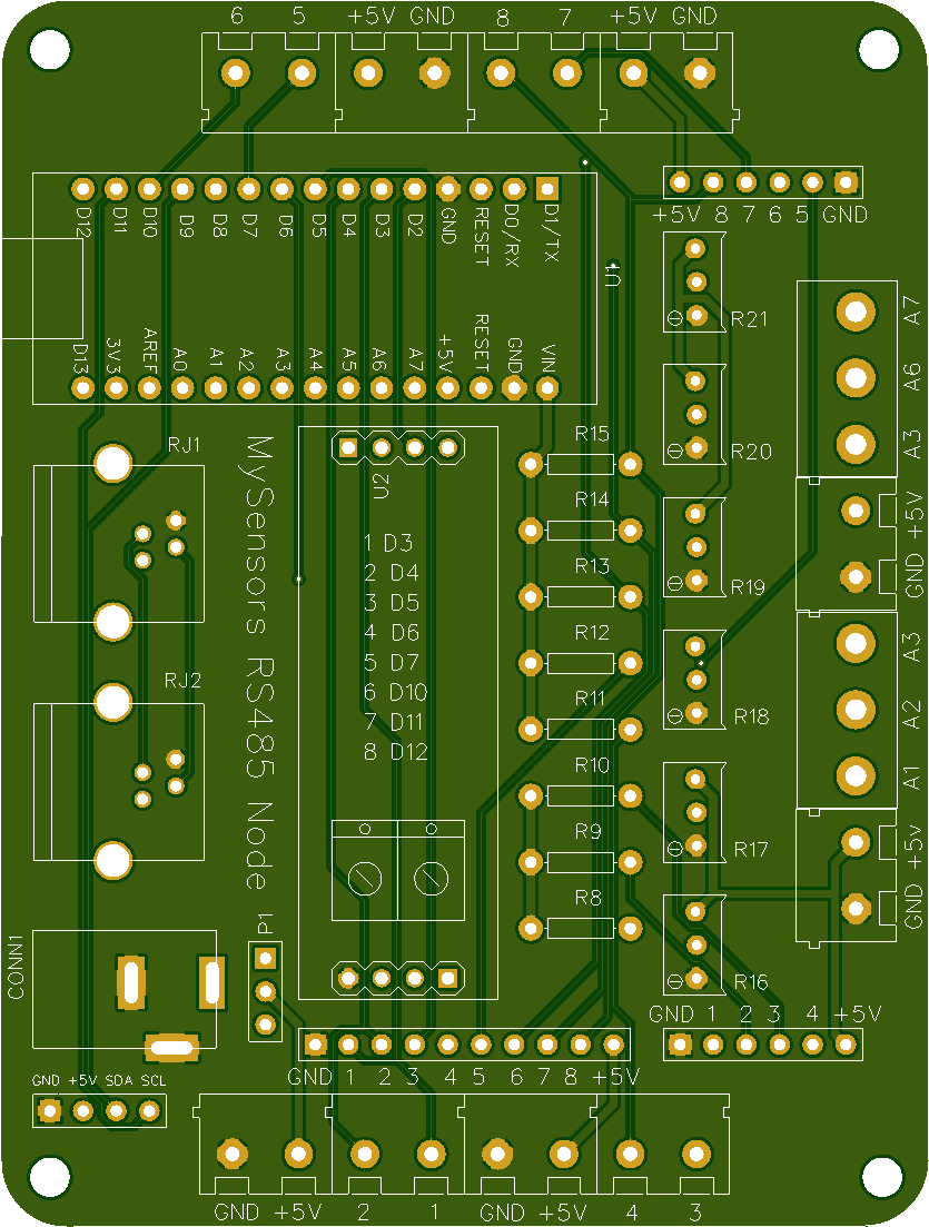
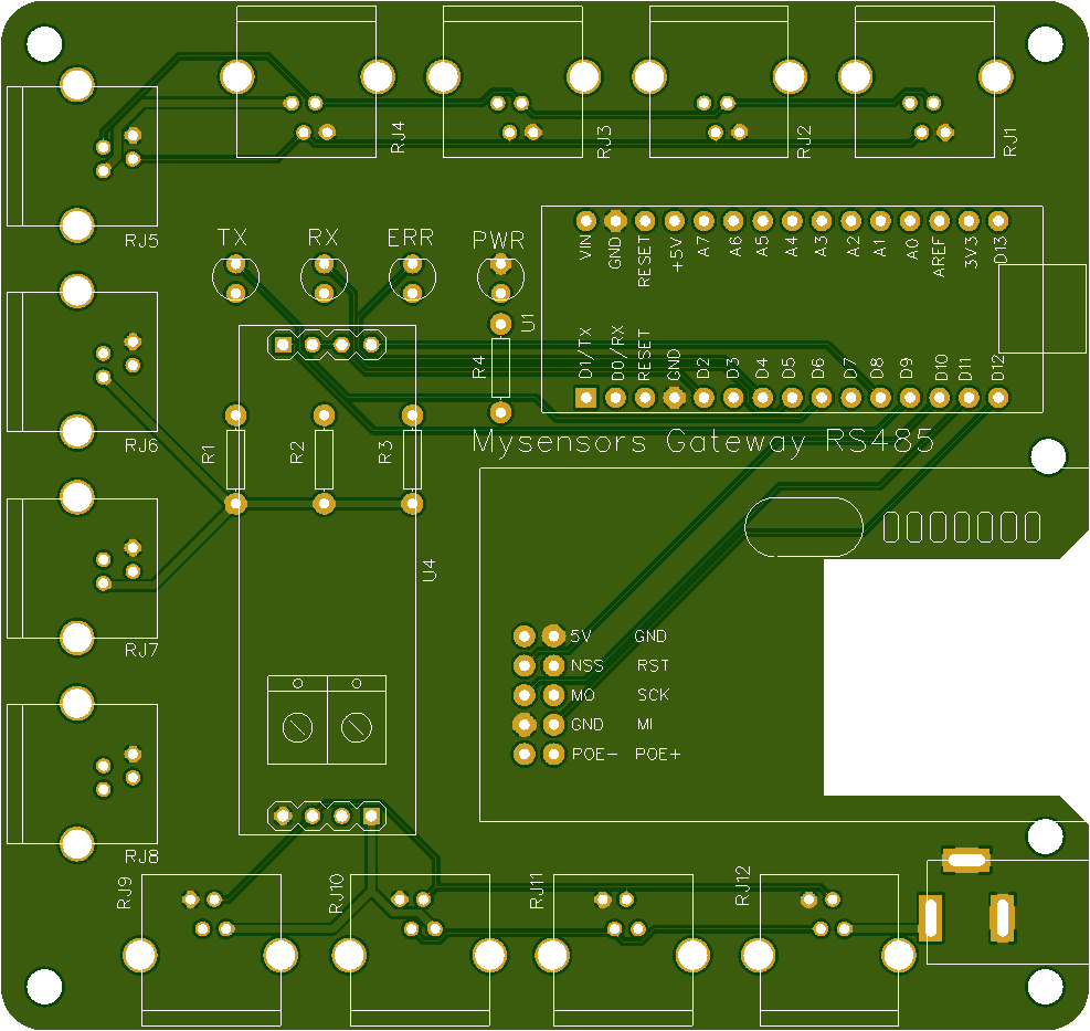
New PCB :
after inversion of the sketch the problem remains the same the NODE sends many infos on the network RS485 but the gateway receive nothing
since the gateway sends a frame from time to time I will wait to see if there is really anything on the RS485 network and if I receive info it means that my node and my gateway do not understand on the RS485 network
Hello
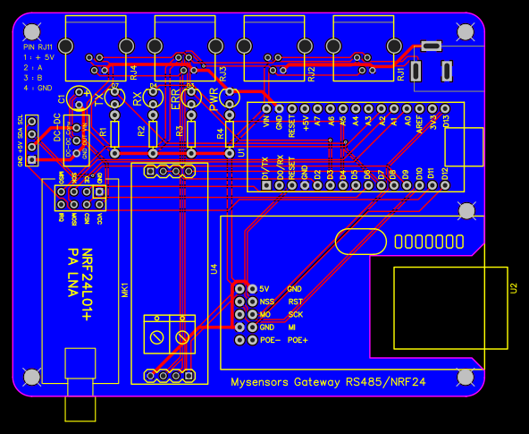
Here is the diagram of my card but since I made some modification I added a module NRF24 but not programmed and the W5100 is not present too, it is a universal turntable.
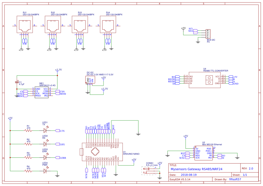
with my test skit no problem it works with the same component on the PCB the only thing weird is that the NODE sends much info on the RS485 but not the gateway
I will try to reverse the turntables and sketches to see if it is not an arduino problem or not
I use for each pcb arduino nano:
here is my test sketch:
Master :
#include <SoftwareSerial.h>

int MAX485_Receiver_Output_PIN = 8;
int MAX485_Driver_Input_PIN = 9;
int MAX485_Driver_Output_Enable_PIN = 2;

int debug_led = 13;

SoftwareSerial software_serial (MAX485_Receiver_Output_PIN, MAX485_Driver_Input_PIN); // RX, TX

void setup()
{
  Serial.begin(115200); // begin hardware serial
  software_serial.begin(9600); // begin software serial

  pinMode(MAX485_Driver_Output_Enable_PIN, OUTPUT);
  digitalWrite(MAX485_Driver_Output_Enable_PIN, HIGH); // this disables Receiver Output Enable and enables Driver Output Enable
}

void loop()
{
   byte to_send = 0; // declare the byte to be sent to the slaves though, init as 0
  int rate;

  while (true)
  {
    // invert the byte to be sent
    if (to_send == 1) to_send = 0;
    else if (to_send == 0) to_send = 1;

    Serial.print("Sending: ");
    Serial.println(to_send);

    digitalWrite(debug_led, to_send);

    rate = map(analogRead(5), 0, 1023, 0, 1000);

    software_serial.write(to_send); // send our byte out to the MAX485

    delay(rate);
  }
}
Slave :
#include <SoftwareSerial.h>

int MAX485_Receiver_Output_PIN = 8;
int MAX485_Driver_Input_PIN = 9;
int MAX485_Driver_Output_Enable_PIN = 2;

int debug_led_PIN = 13;

SoftwareSerial software_serial (MAX485_Receiver_Output_PIN, MAX485_Driver_Input_PIN); // RX, TX

void setup()
{

  Serial.begin(115200); // begin hardware serial
  software_serial.begin(9600); // begin software serial

  pinMode(MAX485_Driver_Output_Enable_PIN, OUTPUT);
  digitalWrite(MAX485_Driver_Output_Enable_PIN, LOW);

  pinMode(debug_led_PIN, OUTPUT);

}

void loop() // run over and over
{
  byte k;

  if (software_serial.available() > 0) // make sure there is something to read
  {
    k = software_serial.read();// read in a single byte from the serial port
    Serial.println(k);
    digitalWrite(debug_led_PIN, k);
  }
}
this skit makes it possible to blink the led 13 with a variation of the potentiometer which changes the delay of the blinking
after testing by putting the serial connections live (and well reversed the TX and RX) there is no communication between the node and the gateway while with my test sketch that function, CAUTION: I do not use the same library as mysensors:
on mysensors we use : AltSoftSerial
on my test sketch I use : SoftwareSerial
no need to put the debug because it's the same as above
I try with another sketch for rs485 and my two arduino comunique well together with the same hardware configuration.
did I notice the node sends many infos on the RS485 network (tested with a sketch snifer RS485) but the gateway send anything on the RS485 network
if someone has already done mysensors on the RS485 thank you for sharing your skit to find what is wrong
Hello and thank you for answering me, here are the log:
Debug Gateway :
0;255;3;0;9;0 MCO:BGN:INIT GW,CP=RSNGA---,VER=2.3.0
0;255;3;0;9;4 TSM:INIT
0;255;3;0;9;6 TSF:WUR:MS=0
0;255;3;0;9;9 TSM:INIT:TSP OK
0;255;3;0;9;11 TSM:INIT:GW MODE
0;255;3;0;9;14 TSM:READY:ID=0,PAR=0,DIS=0
0;255;3;0;9;18 MCO:REG:NOT NEEDED
0;255;3;0;14;Gateway startup complete.
0;255;0;0;18;2.3.0
0;255;3;0;9;22 MCO:BGN:STP
0;255;3;0;9;28 MCO:BGN:INIT OK,TSP=1
Debug Node :
 __  __       ____
|  \/  |_   _/ ___|  ___ _ __  ___  ___  _ __ ___
| |\/| | | | \___ \ / _ \ `_ \/ __|/ _ \| `__/ __|
| |  | | |_| |___| |  __/ | | \__ \  _  | |  \__ \
|_|  |_|\__, |____/ \___|_| |_|___/\___/|_|  |___/
        |___/                      2.3.0

16 MCO:BGN:INIT NODE,CP=RSNNA---,VER=2.3.0
25 TSM:INIT
26 TSF:WUR:MS=0
28 TSM:INIT:TSP OK
29 TSM:INIT:STATID=6
31 TSF:SID:OK,ID=6
33 TSM:FPAR
34 TSM:FPAR:STATP=0
36 TSM:ID
37 TSM:ID:OK
38 TSM:UPL
57 TSF:MSG:SEND,6-6-0-0,s=255,c=3,t=24,pt=1,l=1,sg=0,ft=0,st=OK:1
2064 TSM:UPL
2082 TSF:MSG:SEND,6-6-0-0,s=255,c=3,t=24,pt=1,l=1,sg=0,ft=0,st=OK:1
4089 TSM:UPL
4108 TSF:MSG:SEND,6-6-0-0,s=255,c=3,t=24,pt=1,l=1,sg=0,ft=0,st=OK:1
6115 TSM:UPL
6133 TSF:MSG:SEND,6-6-0-0,s=255,c=3,t=24,pt=1,l=1,sg=0,ft=0,st=OK:1
8140 !TSM:UPL:FAIL
8141 TSM:FPAR
8143 TSM:FPAR:STATP=0
8145 TSM:ID
8146 TSM:ID:OK
8147 TSM:UPL
8167 TSF:MSG:SEND,6-6-0-0,s=255,c=3,t=24,pt=1,l=1,sg=0,ft=0,st=OK:1
10174 TSM:UPL
10192 TSF:MSG:SEND,6-6-0-0,s=255,c=3,t=24,pt=1,l=1,sg=0,ft=0,st=OK:1
12200 TSM:UPL
12219 TSF:MSG:SEND,6-6-0-0,s=255,c=3,t=24,pt=1,l=1,sg=0,ft=0,st=OK:1
14226 TSM:UPL
14244 TSF:MSG:SEND,6-6-0-0,s=255,c=3,t=24,pt=1,l=1,sg=0,ft=0,st=OK:1
16252 !TSM:UPL:FAIL
16253 TSM:FPAR
16256 TSM:FPAR:STATP=0
16258 TSM:ID
16259 TSM:ID:OK
16261 TSM:UPL
the sketch are the default ones for the RS485
Thank you for your help
Hello
I created a gateway RS485, I inject a comunication test sketch and it works without problem. when I inject the sketch mysensors 2.3.0 RS485 with the examples that are on the site it does not work, the node sends many infos on the RS485 but the gateway does not respond, while in the debug of the gateway does not mark no mistake and send well from time to time frames.
if you need more info I will put my codes
thank you for your help because it's been more days that I tear my hair lol
@manutremo said in Problem Gateway and Node:
hello and thanks again for your help
after the modifications of the LEVEL, I still have the same problem
here is the debug of the node:
 __  __       ____
|  \/  |_   _/ ___|  ___ _ __  ___  ___  _ __ ___
| |\/| | | | \___ \ / _ \ `_ \/ __|/ _ \| `__/ __|
| |  | | |_| |___| |  __/ | | \__ \  _  | |  \__ \
|_|  |_|\__, |____/ \___|_| |_|___/\___/|_|  |___/
        |___/                      2.2.0-beta


17 MCO:BGN:INIT REPEATER,CP=RNNRA---,VER=2.2.0-beta
26 MCO:BGN:BFR
28 TSM:INIT
29 TSF:WUR:MS=0
36 TSM:INIT:TSP OK
37 TSM:FPAR
40 TSF:MSG:SEND,255-255-255-255,s=255,c=3,t=7,pt=0,l=0,sg=0,ft=0,st=OK:
2048 !TSM:FPAR:NO REPLY
2050 TSM:FPAR
2052 TSF:MSG:SEND,255-255-255-255,s=255,c=3,t=7,pt=0,l=0,sg=0,ft=0,st=OK:
4060 !TSM:FPAR:NO REPLY
4062 TSM:FPAR
4064 TSF:MSG:SEND,255-255-255-255,s=255,c=3,t=7,pt=0,l=0,sg=0,ft=0,st=OK:
6072 !TSM:FPAR:NO REPLY
6074 TSM:FPAR
6076 TSF:MSG:SEND,255-255-255-255,s=255,c=3,t=7,pt=0,l=0,sg=0,ft=0,st=OK:
8084 !TSM:FPAR:FAIL
8085 TSM:FAIL:CNT=1
8087 TSM:FAIL:DIS
8089 TSF:TDI:TSL
and here is the debug of the gateway:
0 MCO:BGN:INIT GW,CP=RNNGA---,VER=2.2.0-beta
3 TSM:INIT
4 TSF:WUR:MS=0
11 TSM:INIT:TSP OK
13 TSM:INIT:GW MODE
15 TSM:READY:ID=0,PAR=0,DIS=0
17 MCO:REG:NOT NEEDED
IP: 192.168.20.210
1320 MCO:BGN:STP
1323 MCO:BGN:INIT OK,TSP=1
the code of the node:
/**
 * The MySensors Arduino library handles the wireless radio link and protocol
 * between your home built sensors/actuators and HA controller of choice.
 * The sensors forms a self healing radio network with optional repeaters. Each
 * repeater and gateway builds a routing tables in EEPROM which keeps track of the
 * network topology allowing messages to be routed to nodes.
 *
 * Created by Henrik Ekblad <henrik.ekblad@mysensors.org>
 * Copyright (C) 2013-2015 Sensnology AB
 * Full contributor list: https://github.com/mysensors/Arduino/graphs/contributors
 *
 * Documentation: http://www.mysensors.org
 * Support Forum: http://forum.mysensors.org
 *
 * This program is free software; you can redistribute it and/or
 * modify it under the terms of the GNU General Public License
 * version 2 as published by the Free Software Foundation.
 *
 *******************************
 *
 * REVISION HISTORY
 * Version 1.0 - Henrik Ekblad
 *
 * DESCRIPTION
 * Example sketch showing how to control physical relays.
 * This example will remember relay state after power failure.
 * http://www.mysensors.org/build/relay
 */

// Enable debug prints to serial monitor
#define MY_DEBUG

// Enable and select radio type attached
#define MY_RADIO_NRF24
//#define MY_RADIO_NRF5_ESB
//#define MY_RADIO_RFM69
//#define MY_RADIO_RFM95

#define MY_RF24_PA_LEVEL RF24_PA_MIN


// Enable repeater functionality for this node
#define MY_REPEATER_FEATURE

#include <MySensors.h>

#define RELAY_1  3  // Arduino Digital I/O pin number for first relay (second on pin+1 etc)
#define NUMBER_OF_RELAYS 1 // Total number of attached relays
#define RELAY_ON 1  // GPIO value to write to turn on attached relay
#define RELAY_OFF 0 // GPIO value to write to turn off attached relay


void before()
{
	for (int sensor=1, pin=RELAY_1; sensor<=NUMBER_OF_RELAYS; sensor++, pin++) {
		// Then set relay pins in output mode
		pinMode(pin, OUTPUT);
		// Set relay to last known state (using eeprom storage)
		digitalWrite(pin, loadState(sensor)?RELAY_ON:RELAY_OFF);
	}
}

void setup()
{

}

void presentation()
{
	// Send the sketch version information to the gateway and Controller
	sendSketchInfo("Relay", "1.0");

	for (int sensor=1, pin=RELAY_1; sensor<=NUMBER_OF_RELAYS; sensor++, pin++) {
		// Register all sensors to gw (they will be created as child devices)
		present(sensor, S_BINARY);
	}
}


void loop()
{

}

void receive(const MyMessage &message)
{
	// We only expect one type of message from controller. But we better check anyway.
	if (message.type==V_STATUS) {
		// Change relay state
		digitalWrite(message.sensor-1+RELAY_1, message.getBool()?RELAY_ON:RELAY_OFF);
		// Store state in eeprom
		saveState(message.sensor, message.getBool());
		// Write some debug info
		Serial.print("Incoming change for sensor:");
		Serial.print(message.sensor);
		Serial.print(", New status: ");
		Serial.println(message.getBool());
	}
}
the code of the gateway:
/**
 * The MySensors Arduino library handles the wireless radio link and protocol
 * between your home built sensors/actuators and HA controller of choice.
 * The sensors forms a self healing radio network with optional repeaters. Each
 * repeater and gateway builds a routing tables in EEPROM which keeps track of the
 * network topology allowing messages to be routed to nodes.
 *
 * Created by Henrik Ekblad <henrik.ekblad@mysensors.org>
 * Copyright (C) 2013-2015 Sensnology AB
 * Full contributor list: https://github.com/mysensors/Arduino/graphs/contributors
 *
 * Documentation: http://www.mysensors.org
 * Support Forum: http://forum.mysensors.org
 *
 * This program is free software; you can redistribute it and/or
 * modify it under the terms of the GNU General Public License
 * version 2 as published by the Free Software Foundation.
 *
 *******************************
 *
 * REVISION HISTORY
 * Version 1.0 - Henrik EKblad
 * Contribution by a-lurker and Anticimex,
 * Contribution by Norbert Truchsess <norbert.truchsess@t-online.de>
 * Contribution by Tomas Hozza <thozza@gmail.com>
 *
 *
 * DESCRIPTION
 * The EthernetGateway sends data received from sensors to the ethernet link.
 * The gateway also accepts input on ethernet interface, which is then sent out to the radio network.
 *
 * The GW code is designed for Arduino 328p / 16MHz.  ATmega168 does not have enough memory to run this program.
 *
 * LED purposes:
 * - To use the feature, uncomment MY_DEFAULT_xxx_LED_PIN in the sketch below
 * - RX (green) - blink fast on radio message recieved. In inclusion mode will blink fast only on presentation recieved
 * - TX (yellow) - blink fast on radio message transmitted. In inclusion mode will blink slowly
 * - ERR (red) - fast blink on error during transmission error or recieve crc error
 *
 * See http://www.mysensors.org/build/ethernet_gateway for wiring instructions.
 *
 */

// Enable debug prints to serial monitor
#define MY_DEBUG

// Enable and select radio type attached
#define MY_RADIO_NRF24
//#define MY_RADIO_NRF5_ESB
//#define MY_RADIO_RFM69
//#define MY_RADIO_RFM95

#define MY_RF24_PA_LEVEL RF24_PA_MIN

// Enable gateway ethernet module type
#define MY_GATEWAY_W5100

// W5100 Ethernet module SPI enable (optional if using a shield/module that manages SPI_EN signal)
//#define MY_W5100_SPI_EN 4

//#define MY_RF24_PA_LEVEL RF24_PA_LOW

// Enable Soft SPI for NRF radio (note different radio wiring is required)
// The W5100 ethernet module seems to have a hard time co-operate with
// radio on the same spi bus.
#if !defined(MY_W5100_SPI_EN) && !defined(ARDUINO_ARCH_SAMD)
#define MY_SOFTSPI
#define MY_SOFT_SPI_SCK_PIN 14
#define MY_SOFT_SPI_MISO_PIN 16
#define MY_SOFT_SPI_MOSI_PIN 15
#endif

// When W5100 is connected we have to move CE/CSN pins for NRF radio
#ifndef MY_RF24_CE_PIN
#define MY_RF24_CE_PIN 5
#endif
#ifndef MY_RF24_CS_PIN
#define MY_RF24_CS_PIN 6
#endif

// Enable UDP communication
//#define MY_USE_UDP  // If using UDP you need to set MY_CONTROLLER_IP_ADDRESS below

// Enable MY_IP_ADDRESS here if you want a static ip address (no DHCP)
#define MY_IP_ADDRESS 192,168,20,210

// If using static ip you can define Gateway and Subnet address as well
#define MY_IP_GATEWAY_ADDRESS 192,168,20,254
#define MY_IP_SUBNET_ADDRESS 255,255,255,0

// Renewal period if using DHCP
//#define MY_IP_RENEWAL_INTERVAL 60000

// The port to keep open on node server mode / or port to contact in client mode
#define MY_PORT 5003

// Controller ip address. Enables client mode (default is "server" mode).
// Also enable this if MY_USE_UDP is used and you want sensor data sent somewhere.
//#define MY_CONTROLLER_IP_ADDRESS 192, 168, 178, 254

// The MAC address can be anything you want but should be unique on your network.
// Newer boards have a MAC address printed on the underside of the PCB, which you can (optionally) use.
// Note that most of the Ardunio examples use  "DEAD BEEF FEED" for the MAC address.
#define MY_MAC_ADDRESS 0xDE, 0xAD, 0xBE, 0xEF, 0xFE, 0xED

// Enable inclusion mode
#define MY_INCLUSION_MODE_FEATURE
// Enable Inclusion mode button on gateway
//#define MY_INCLUSION_BUTTON_FEATURE
// Set inclusion mode duration (in seconds)
#define MY_INCLUSION_MODE_DURATION 60
// Digital pin used for inclusion mode button
//#define MY_INCLUSION_MODE_BUTTON_PIN  3

// Set blinking period
#define MY_DEFAULT_LED_BLINK_PERIOD 300

// Flash leds on rx/tx/err
// Uncomment to override default HW configurations
#define MY_DEFAULT_ERR_LED_PIN 7  // Error led pin
#define MY_DEFAULT_RX_LED_PIN  8  // Receive led pin
#define MY_DEFAULT_TX_LED_PIN  9  // Transmit led pin

#if defined(MY_USE_UDP)
#include <EthernetUdp.h>
#endif
#include <Ethernet.h>
#include <MySensors.h>

void setup()
{
	// Setup locally attached sensors
}

void presentation()
{
	// Present locally attached sensors here
}

void loop()
{
	// Send locally attached sensors data here
}
Hello everyone
I come back to you because I can no longer operate my gateway, I explain:
here is the log of starting my gateway:
0 MCO:BGN:INIT GW,CP=RNNGA---,VER=2.2.0-beta
3 TSM:INIT
4 TSF:WUR:MS=0
11 TSM:INIT:TSP OK
13 TSM:INIT:GW MODE
15 TSM:READY:ID=0,PAR=0,DIS=0
17 MCO:REG:NOT NEEDED
IP: 192.168.20.210
1320 MCO:BGN:STP
1323 MCO:BGN:INIT OK,TSP=1```
Insert Code Here
until all is well (finally I think)
but the gateway stays as it does not communicate it sends nothing to the node
here is the code:
/**
 * The MySensors Arduino library handles the wireless radio link and protocol
 * between your home built sensors/actuators and HA controller of choice.
 * The sensors forms a self healing radio network with optional repeaters. Each
 * repeater and gateway builds a routing tables in EEPROM which keeps track of the
 * network topology allowing messages to be routed to nodes.
 *
 * Created by Henrik Ekblad <henrik.ekblad@mysensors.org>
 * Copyright (C) 2013-2015 Sensnology AB
 * Full contributor list: https://github.com/mysensors/Arduino/graphs/contributors
 *
 * Documentation: http://www.mysensors.org
 * Support Forum: http://forum.mysensors.org
 *
 * This program is free software; you can redistribute it and/or
 * modify it under the terms of the GNU General Public License
 * version 2 as published by the Free Software Foundation.
 *
 *******************************
 *
 * REVISION HISTORY
 * Version 1.0 - Henrik EKblad
 * Contribution by a-lurker and Anticimex,
 * Contribution by Norbert Truchsess <norbert.truchsess@t-online.de>
 * Contribution by Tomas Hozza <thozza@gmail.com>
 *
 *
 * DESCRIPTION
 * The EthernetGateway sends data received from sensors to the ethernet link.
 * The gateway also accepts input on ethernet interface, which is then sent out to the radio network.
 *
 * The GW code is designed for Arduino 328p / 16MHz.  ATmega168 does not have enough memory to run this program.
 *
 * LED purposes:
 * - To use the feature, uncomment MY_DEFAULT_xxx_LED_PIN in the sketch below
 * - RX (green) - blink fast on radio message recieved. In inclusion mode will blink fast only on presentation recieved
 * - TX (yellow) - blink fast on radio message transmitted. In inclusion mode will blink slowly
 * - ERR (red) - fast blink on error during transmission error or recieve crc error
 *
 * See http://www.mysensors.org/build/ethernet_gateway for wiring instructions.
 *
 */

// Enable debug prints to serial monitor
#define MY_DEBUG

// Enable and select radio type attached
#define MY_RADIO_NRF24
//#define MY_RADIO_NRF5_ESB
//#define MY_RADIO_RFM69
//#define MY_RADIO_RFM95

// Enable gateway ethernet module type
#define MY_GATEWAY_W5100

// W5100 Ethernet module SPI enable (optional if using a shield/module that manages SPI_EN signal)
//#define MY_W5100_SPI_EN 4

// Enable Soft SPI for NRF radio (note different radio wiring is required)
// The W5100 ethernet module seems to have a hard time co-operate with
// radio on the same spi bus.
#if !defined(MY_W5100_SPI_EN) && !defined(ARDUINO_ARCH_SAMD)
#define MY_SOFTSPI
#define MY_SOFT_SPI_SCK_PIN 14
#define MY_SOFT_SPI_MISO_PIN 16
#define MY_SOFT_SPI_MOSI_PIN 15
#endif

// When W5100 is connected we have to move CE/CSN pins for NRF radio
#ifndef MY_RF24_CE_PIN
#define MY_RF24_CE_PIN 5
#endif
#ifndef MY_RF24_CS_PIN
#define MY_RF24_CS_PIN 6
#endif

// Enable UDP communication
//#define MY_USE_UDP  // If using UDP you need to set MY_CONTROLLER_IP_ADDRESS below

// Enable MY_IP_ADDRESS here if you want a static ip address (no DHCP)
#define MY_IP_ADDRESS 192,168,20,210

// If using static ip you can define Gateway and Subnet address as well
#define MY_IP_GATEWAY_ADDRESS 192,168,20,254
#define MY_IP_SUBNET_ADDRESS 255,255,255,0

// Renewal period if using DHCP
//#define MY_IP_RENEWAL_INTERVAL 60000

// The port to keep open on node server mode / or port to contact in client mode
#define MY_PORT 5003

// Controller ip address. Enables client mode (default is "server" mode).
// Also enable this if MY_USE_UDP is used and you want sensor data sent somewhere.
//#define MY_CONTROLLER_IP_ADDRESS 192, 168, 178, 254

// The MAC address can be anything you want but should be unique on your network.
// Newer boards have a MAC address printed on the underside of the PCB, which you can (optionally) use.
// Note that most of the Ardunio examples use  "DEAD BEEF FEED" for the MAC address.
#define MY_MAC_ADDRESS 0xDE, 0xAD, 0xBE, 0xEF, 0xFE, 0xED

// Enable inclusion mode
#define MY_INCLUSION_MODE_FEATURE
// Enable Inclusion mode button on gateway
//#define MY_INCLUSION_BUTTON_FEATURE
// Set inclusion mode duration (in seconds)
#define MY_INCLUSION_MODE_DURATION 60
// Digital pin used for inclusion mode button
//#define MY_INCLUSION_MODE_BUTTON_PIN  3

// Set blinking period
#define MY_DEFAULT_LED_BLINK_PERIOD 300

// Flash leds on rx/tx/err
// Uncomment to override default HW configurations
#define MY_DEFAULT_ERR_LED_PIN 7  // Error led pin
#define MY_DEFAULT_RX_LED_PIN  8  // Receive led pin
#define MY_DEFAULT_TX_LED_PIN  9  // Transmit led pin

#if defined(MY_USE_UDP)
#include <EthernetUdp.h>
#endif
#include <Ethernet.h>
#include <MySensors.h>

void setup()
{
	// Setup locally attached sensors
}

void presentation()
{
	// Present locally attached sensors here
}

void loop()
{
	// Send locally attached sensors data here
}
but I do not see why because my node sends a lot of info, I even put capacitor for the 3.3V but the same
I changed several times RF module and the same
a yes from time to time I have this:
900005 TSF:SAN:OK
Thank you for your help