Navigation

    • Register
    • Login
    • OpenHardware.io
    • Categories
    • Recent
    • Tags
    • Popular
    1. Home
    2. rafael156
    3. Posts
    • Profile
    • Following
    • Followers
    • Topics
    • Posts
    • Best
    • Groups

    Posts made by rafael156

    • selling mysensors sensebender gateway

      i'm selling my ethernet sensebender gateway because i don't need it anymore. it works fine and has the latest mysensors-lib (2.3.2) installed.
      the board cost me 20€, the case about 10€, the rest about 8€. The set consists of the sensebender GW, the ethernet shield and the NRF module.
      I would sell the whole set for 20€ + 3€ shipping from Germany.
      if you are seriously interested, please contact me.

      20210108_143734.jpg 20210108_143711.jpg 20210108_143703.jpg

      posted in Hardware
      rafael156
      rafael156
    • RE: Sensebender multiple controller

      ok, i tried a username and password for mqtt binding (http://www.steves-internet-guide.com/mqtt-username-password-example/), but getting the error "connection can´t be established".
      Is it a bug? i found several threads with the same failure...

      posted in Troubleshooting
      rafael156
      rafael156
    • RE: Sensebender multiple controller

      if i understood everything correctly, only the auto-id feature isn't available in mqtt, right?
      I can still use autodiscovery and ota, right?

      posted in Troubleshooting
      rafael156
      rafael156
    • Sensebender multiple controller

      Hello!
      How is it possible to operate two controllers simultaneously with one Sensebender Gateway?
      i have this sketch on the sensebender, but i can only connect openhab OR mycontroller.org, not both at the same time.
      The last controller that connects to the sensebender gets the data. the other one doesn't.

      Is this due to the sketch?

      /*
       * The MySensors Arduino library handles the wireless radio link and protocol
       * between your home built sensors/actuators and HA controller of choice.
       * The sensors forms a self healing radio network with optional repeaters. Each
       * repeater and gateway builds a routing tables in EEPROM which keeps track of the
       * network topology allowing messages to be routed to nodes.
       *
       * Created by Henrik Ekblad <henrik.ekblad@mysensors.org>
       * Copyright (C) 2013-2018 Sensnology AB
       * Full contributor list: https://github.com/mysensors/MySensors/graphs/contributors
       *
       * Documentation: http://www.mysensors.org
       * Support Forum: http://forum.mysensors.org
       *
       * This program is free software; you can redistribute it and/or
       * modify it under the terms of the GNU General Public License
       * version 2 as published by the Free Software Foundation.
       *
       *******************************
       *
       * REVISION HISTORY
       * Version 1.0 - Henrik EKblad
       * Contribution by a-lurker and Anticimex,
       * Contribution by Norbert Truchsess <norbert.truchsess@t-online.de>
       * Contribution by Tomas Hozza <thozza@gmail.com>
       *
       *
       * DESCRIPTION
       * The EthernetGateway sends data received from sensors to the ethernet link.
       * The gateway also accepts input on ethernet interface, which is then sent out to the radio network.
       *
       * The GW code is designed for Arduino 328p / 16MHz.  ATmega168 does not have enough memory to run this program.
       *
       * LED purposes:
       * - To use the feature, uncomment MY_DEFAULT_xxx_LED_PIN in the sketch below
       * - RX (green) - blink fast on radio message received. In inclusion mode will blink fast only on presentation received
       * - TX (yellow) - blink fast on radio message transmitted. In inclusion mode will blink slowly
       * - ERR (red) - fast blink on error during transmission error or receive crc error
       *
       * See http://www.mysensors.org/build/ethernet_gateway for wiring instructions.
       *
       */
      
      //@changed
      // Define sketch version
      #define SKETCH_VERSION "0.4"
      //@changed
      
      // Enable debug prints to serial monitor
      #define MY_DEBUG
      
      // Enable and select radio type attached
      #define MY_RADIO_RF24
      //#define MY_RADIO_NRF5_ESB
      //#define MY_RADIO_RFM69
      //#define MY_RADIO_RFM95
      
      // Enable gateway ethernet module type
      #define MY_GATEWAY_W5100
      #define MY_GATEWAY_MAX_CLIENTS  3
      
      // W5100 Ethernet module SPI enable (optional if using a shield/module that manages SPI_EN signal)
      //#define MY_W5100_SPI_EN 4
      
      // Enable Soft SPI for NRF radio (note different radio wiring is required)
      // The W5100 ethernet module seems to have a hard time co-operate with
      // radio on the same spi bus.
      #if !defined(MY_W5100_SPI_EN) && !defined(ARDUINO_ARCH_SAMD)
      #define MY_SOFTSPI
      #define MY_SOFT_SPI_SCK_PIN 14
      #define MY_SOFT_SPI_MISO_PIN 16
      #define MY_SOFT_SPI_MOSI_PIN 15
      #endif
      
      // When W5100 is connected we have to move CE/CSN pins for NRF radio
      #ifndef MY_RF24_CE_PIN
      #define MY_RF24_CE_PIN 5
      #endif
      #ifndef MY_RF24_CS_PIN
      #define MY_RF24_CS_PIN 6
      #endif
      
      // Enable UDP communication
      //#define MY_USE_UDP  // If using UDP you need to set MY_CONTROLLER_IP_ADDRESS below
      
      // Enable MY_IP_ADDRESS here if you want a static ip address (no DHCP)
      #define MY_IP_ADDRESS 192,168,1,110
      
      // If using static ip you can define Gateway and Subnet address as well
      #define MY_IP_GATEWAY_ADDRESS 192,168,1,1
      #define MY_IP_SUBNET_ADDRESS 255,255,255,0
      
      // Renewal period if using DHCP
      //#define MY_IP_RENEWAL_INTERVAL 60000
      
      // The port to keep open on node server mode / or port to contact in client mode
      #define MY_PORT 5003
      
      // Controller ip address. Enables client mode (default is "server" mode).
      // Also enable this if MY_USE_UDP is used and you want sensor data sent somewhere.
      //#define MY_CONTROLLER_IP_ADDRESS 192, 168, 178, 254
      
      // The MAC address can be anything you want but should be unique on your network.
      // Newer boards have a MAC address printed on the underside of the PCB, which you can (optionally) use.
      // Note that most of the Arduino examples use  "DEAD BEEF FEED" for the MAC address.
      #define MY_MAC_ADDRESS XXXXXXXXXXX
      
      // Enable inclusion mode
      #define MY_INCLUSION_MODE_FEATURE
      // Enable Inclusion mode button on gateway
      //#define MY_INCLUSION_BUTTON_FEATURE
      // Set inclusion mode duration (in seconds)
      #define MY_INCLUSION_MODE_DURATION 60
      // Digital pin used for inclusion mode button
      //#define MY_INCLUSION_MODE_BUTTON_PIN  3
      
      // Set blinking period
      #define MY_DEFAULT_LED_BLINK_PERIOD 300
      
      // Flash leds on rx/tx/err
      // Uncomment to override default HW configurations
      //#define MY_DEFAULT_ERR_LED_PIN 7  // Error led pin
      //#define MY_DEFAULT_RX_LED_PIN  8  // Receive led pin
      //#define MY_DEFAULT_TX_LED_PIN  9  // Transmit led pin
      
      #if defined(MY_USE_UDP)
      #include <EthernetUdp.h>
      #endif
      #include <Ethernet.h>
      #include <MySensors.h>
      
      //@changed
      #include <SD.h>
      #include <drivers/ATSHA204/ATSHA204.cpp>
      
      Sd2Card card;
      
      #define EEPROM_VERIFICATION_ADDRESS 0x01
      
      static uint8_t num_of_leds = 5;
      static uint8_t leds[] = {LED_BLUE, LED_RED, LED_GREEN, LED_YELLOW, LED_ORANGE};
      //@changed
      
      void setup()
      {
      	// Setup locally attached sensors
       sleep(250);      // wait for the W5100
      }
      
      void presentation()
      {
      	// Present locally attached sensors here
      }
      
      void loop()
      {
      	// Send locally attached sensors data here
      }


      //@changed
      void preHwInit()
      {
      
        pinMode(MY_SWC1, INPUT_PULLUP);
        pinMode(MY_SWC2, INPUT_PULLUP);
        if (digitalRead(MY_SWC1) && digitalRead(MY_SWC2)) {
          return;
        }
      
        uint8_t tests = 0;
      
        for (int i=0; i< num_of_leds; i++) {
          pinMode(leds[i], OUTPUT);
        }
        if (digitalRead(MY_SWC1)) {
          uint8_t led_state = 0;
          while (!Serial) {
            digitalWrite(LED_BLUE, led_state);
            led_state ^= 0x01;
            delay(500);
          } // Wait for USB to be connected, before spewing out data.
        }
        digitalWrite(LED_BLUE, LOW);
        if (Serial) {
          Serial.println("Sensebender GateWay test routine");
          Serial.print("MySensors core version : ");
          Serial.println(MYSENSORS_LIBRARY_VERSION);
          Serial.print("GateWay sketch version : ");
          Serial.println(SKETCH_VERSION);
          Serial.println("----------------------------------");
          Serial.println();
        }
        if (testSha204()) {
          digitalWrite(LED_GREEN, HIGH);
          tests++;
        }
        if (testSDCard()) {
          digitalWrite(LED_YELLOW, HIGH);
          tests++;
        }
      
        if (testEEProm()) {
          digitalWrite(LED_ORANGE, HIGH);
          tests++;
        }
        if (testAnalog()) {
          digitalWrite(LED_BLUE, HIGH);
          tests++;
        }
        if (tests == 4) {
          while(1) {
            for (int i=0; i<num_of_leds; i++) {
              digitalWrite(leds[i], HIGH);
              delay(200);
              digitalWrite(leds[i], LOW);
            }
          }
        } else {
          while (1) {
            digitalWrite(LED_RED, HIGH);
            delay(200);
            digitalWrite(LED_RED, LOW);
            delay(200);
          }
        }
      
      }
      
      bool testSha204()
      {
        uint8_t rx_buffer[SHA204_RSP_SIZE_MAX];
        uint8_t ret_code;
        if (Serial) {
          Serial.print("- > SHA204 ");
        }
        atsha204_init(MY_SIGNING_ATSHA204_PIN);
        ret_code = atsha204_wakeup(rx_buffer);
      
        if (ret_code == SHA204_SUCCESS) {
          ret_code = atsha204_getSerialNumber(rx_buffer);
          if (ret_code != SHA204_SUCCESS) {
            if (Serial) {
              Serial.println(F("Failed to obtain device serial number. Response: "));
            }
            Serial.println(ret_code, HEX);
          } else {
            if (Serial) {
              Serial.print(F("Ok (serial : "));
              for (int i=0; i<9; i++) {
                if (rx_buffer[i] < 0x10) {
                  Serial.print('0'); // Because Serial.print does not 0-pad HEX
                }
                Serial.print(rx_buffer[i], HEX);
              }
              Serial.println(")");
            }
            return true;
          }
        } else {
          if (Serial) {
            Serial.println(F("Failed to wakeup SHA204"));
          }
        }
        return false;
      }
      
      bool testSDCard()
      {
        if (Serial) {
          Serial.print("- > SD CARD ");
        }
        if (!card.init(SPI_HALF_SPEED, MY_SDCARD_CS)) {
          if (Serial) {
            Serial.println("SD CARD did not initialize!");
          }
        } else {
          if (Serial) {
            Serial.print("SD Card initialized correct! - ");
            Serial.print("type detected : ");
            switch(card.type()) {
            case SD_CARD_TYPE_SD1:
              Serial.println("SD1");
              break;
            case SD_CARD_TYPE_SD2:
              Serial.println("SD2");
              break;
            case SD_CARD_TYPE_SDHC:
              Serial.println("SDHC");
              break;
            default:
              Serial.println("Unknown");
            }
          }
          return true;
        }
        return false;
      }
      
      bool testEEProm()
      {
        uint8_t eeprom_d1, eeprom_d2;
        SerialUSB.print(" -> EEPROM ");
        eeprom_d1 = hwReadConfig(EEPROM_VERIFICATION_ADDRESS);
        delay(500);
        eeprom_d1 = ~eeprom_d1; // invert the bits
        hwWriteConfig(EEPROM_VERIFICATION_ADDRESS, eeprom_d1);
        delay(500);
        eeprom_d2 = hwReadConfig(EEPROM_VERIFICATION_ADDRESS);
        if (eeprom_d1 == eeprom_d2) {
          SerialUSB.println("PASSED");
          hwWriteConfig(EEPROM_VERIFICATION_ADDRESS, ~eeprom_d1);
          return true;
        }
        SerialUSB.println("FAILED!");
        return false;
      }
      
      bool testAnalog()
      {
        int bat_detect = analogRead(MY_BAT_DETECT);
        Serial.print("-> analog : ");
        Serial.print(bat_detect);
        if (bat_detect < 400 || bat_detect > 650) {
          Serial.println(" Failed");
          return false;
        }
        Serial.println(" Passed");
        return true;
      }
      //@changed```
      posted in Troubleshooting
      rafael156
      rafael156
    • RE: not working Ethernet Gateway (sensebender and/or nano gateway)

      Thanks to everyone who helped! now it would be interesting again, if it also works with the latest SAMD and arduino ide versions...?! has somebody already tested it/ been running?

      posted in Hardware
      rafael156
      rafael156
    • RE: not working Ethernet Gateway (sensebender and/or nano gateway)

      To the Sensebender Board with W5100+NRF24:

      • Sensebender can be flashed via Arduino IDE: Bootloader and Sketch
      • Note versions (work):
        Arduino IDE 1.6.13
        Arduino AVR 1.6.18
        Arduino SAMD 1.6.12
        MySensors SAMD 1.0.5
        MySensors Lib 2.3.1
      • Installed is an Atmel "ATSAMD21J18A-AU".
      • Windows 10 does not recognize the serial port after a few flashes (native USB ATSAMD21J18A-AU). Then the PC must be restarted.
      • the bootloader has to be flashed via SWD interface (e.g. with Atmel JtagICE3):
        -> install Atmel Studio 7 (for JtagICE3 drivers) and erase chip
        -> Connect the pins of the JTAGICE3 to Sensebender:
        JTAGICE3: ARM SWD Pin:
        Pin 1 (TCK) SWDCLK
        Pin 2 (GND) GND
        Pin 4 (VTG) VCC
        Pin 5 (TMS) SWDIO
        Pin 6 (nSRST) nRESET
        -> bootloader about Ardunio IDE flash: Programmer "Atmel EDBG or Atmel Sam ICE"
        -> usb port should now be found automatically (windows 10 has drivers already integrated, install win7.8 driver from MySensors)
      • sketch normal about arduino ide and port selection flashes

      My working Sensebender W5100+NRF24 sketch:

      /*
       * The MySensors Arduino library handles the wireless radio link and protocol
       * between your home built sensors/actuators and HA controller of choice.
       * The sensors forms a self healing radio network with optional repeaters. Each
       * repeater and gateway builds a routing tables in EEPROM which keeps track of the
       * network topology allowing messages to be routed to nodes.
       *
       * Created by Henrik Ekblad <henrik.ekblad@mysensors.org>
       * Copyright (C) 2013-2018 Sensnology AB
       * Full contributor list: https://github.com/mysensors/MySensors/graphs/contributors
       *
       * Documentation: http://www.mysensors.org
       * Support Forum: http://forum.mysensors.org
       *
       * This program is free software; you can redistribute it and/or
       * modify it under the terms of the GNU General Public License
       * version 2 as published by the Free Software Foundation.
       *
       *******************************
       *
       * REVISION HISTORY
       * Version 1.0 - Henrik EKblad
       * Contribution by a-lurker and Anticimex,
       * Contribution by Norbert Truchsess <norbert.truchsess@t-online.de>
       * Contribution by Tomas Hozza <thozza@gmail.com>
       *
       *
       * DESCRIPTION
       * The EthernetGateway sends data received from sensors to the ethernet link.
       * The gateway also accepts input on ethernet interface, which is then sent out to the radio network.
       *
       * The GW code is designed for Arduino 328p / 16MHz.  ATmega168 does not have enough memory to run this program.
       *
       * LED purposes:
       * - To use the feature, uncomment MY_DEFAULT_xxx_LED_PIN in the sketch below
       * - RX (green) - blink fast on radio message received. In inclusion mode will blink fast only on presentation received
       * - TX (yellow) - blink fast on radio message transmitted. In inclusion mode will blink slowly
       * - ERR (red) - fast blink on error during transmission error or receive crc error
       *
       * See http://www.mysensors.org/build/ethernet_gateway for wiring instructions.
       *
       */
      
      //@riss
      // Define sketch version
      #define SKETCH_VERSION "0.4"
      //@riss
      
      // Enable debug prints to serial monitor
      #define MY_DEBUG
      
      // Enable and select radio type attached
      #define MY_RADIO_RF24
      //#define MY_RADIO_NRF5_ESB
      //#define MY_RADIO_RFM69
      //#define MY_RADIO_RFM95
      
      // Enable gateway ethernet module type
      #define MY_GATEWAY_W5100
      #define MY_GATEWAY_MAX_CLIENTS  3
      
      // W5100 Ethernet module SPI enable (optional if using a shield/module that manages SPI_EN signal)
      //#define MY_W5100_SPI_EN 4
      
      // Enable Soft SPI for NRF radio (note different radio wiring is required)
      // The W5100 ethernet module seems to have a hard time co-operate with
      // radio on the same spi bus.
      #if !defined(MY_W5100_SPI_EN) && !defined(ARDUINO_ARCH_SAMD)
      #define MY_SOFTSPI
      #define MY_SOFT_SPI_SCK_PIN 14
      #define MY_SOFT_SPI_MISO_PIN 16
      #define MY_SOFT_SPI_MOSI_PIN 15
      #endif
      
      // When W5100 is connected we have to move CE/CSN pins for NRF radio
      #ifndef MY_RF24_CE_PIN
      #define MY_RF24_CE_PIN 5
      #endif
      #ifndef MY_RF24_CS_PIN
      #define MY_RF24_CS_PIN 6
      #endif
      
      // Enable UDP communication
      //#define MY_USE_UDP  // If using UDP you need to set MY_CONTROLLER_IP_ADDRESS below
      
      // Enable MY_IP_ADDRESS here if you want a static ip address (no DHCP)
      #define MY_IP_ADDRESS 192,168,1,38
      
      // If using static ip you can define Gateway and Subnet address as well
      #define MY_IP_GATEWAY_ADDRESS 192,168,1,1
      #define MY_IP_SUBNET_ADDRESS 255,255,255,0
      
      // Renewal period if using DHCP
      //#define MY_IP_RENEWAL_INTERVAL 60000
      
      // The port to keep open on node server mode / or port to contact in client mode
      #define MY_PORT 5003
      
      // Controller ip address. Enables client mode (default is "server" mode).
      // Also enable this if MY_USE_UDP is used and you want sensor data sent somewhere.
      //#define MY_CONTROLLER_IP_ADDRESS 192, 168, 178, 254
      
      // The MAC address can be anything you want but should be unique on your network.
      // Newer boards have a MAC address printed on the underside of the PCB, which you can (optionally) use.
      // Note that most of the Arduino examples use  "DEAD BEEF FEED" for the MAC address.
      #define MY_MAC_ADDRESS 0xDE, 0xAD, 0xBE, 0xEF, 0xFE, 0xED
      
      // Enable inclusion mode
      #define MY_INCLUSION_MODE_FEATURE
      // Enable Inclusion mode button on gateway
      //#define MY_INCLUSION_BUTTON_FEATURE
      // Set inclusion mode duration (in seconds)
      #define MY_INCLUSION_MODE_DURATION 60
      // Digital pin used for inclusion mode button
      //#define MY_INCLUSION_MODE_BUTTON_PIN  3
      
      // Set blinking period
      #define MY_DEFAULT_LED_BLINK_PERIOD 300
      
      // Flash leds on rx/tx/err
      // Uncomment to override default HW configurations
      //#define MY_DEFAULT_ERR_LED_PIN 7  // Error led pin
      //#define MY_DEFAULT_RX_LED_PIN  8  // Receive led pin
      //#define MY_DEFAULT_TX_LED_PIN  9  // Transmit led pin
      
      #if defined(MY_USE_UDP)
      #include <EthernetUdp.h>
      #endif
      #include <Ethernet.h>
      #include <MySensors.h>
      
      //@riss
      #include <SD.h>
      #include <drivers/ATSHA204/ATSHA204.cpp>
      
      Sd2Card card;
      
      #define EEPROM_VERIFICATION_ADDRESS 0x01
      
      static uint8_t num_of_leds = 5;
      static uint8_t leds[] = {LED_BLUE, LED_RED, LED_GREEN, LED_YELLOW, LED_ORANGE};
      //@riss
      
      void setup()
      {
      	// Setup locally attached sensors
       sleep(250);      // wait for the W5100
      }
      
      void presentation()
      {
      	// Present locally attached sensors here
      }
      
      void loop()
      {
      	// Send locally attached sensors data here
      }


      //@riss
      void preHwInit()
      {
      
        pinMode(MY_SWC1, INPUT_PULLUP);
        pinMode(MY_SWC2, INPUT_PULLUP);
        if (digitalRead(MY_SWC1) && digitalRead(MY_SWC2)) {
          return;
        }
      
        uint8_t tests = 0;
      
        for (int i=0; i< num_of_leds; i++) {
          pinMode(leds[i], OUTPUT);
        }
        if (digitalRead(MY_SWC1)) {
          uint8_t led_state = 0;
          while (!Serial) {
            digitalWrite(LED_BLUE, led_state);
            led_state ^= 0x01;
            delay(500);
          } // Wait for USB to be connected, before spewing out data.
        }
        digitalWrite(LED_BLUE, LOW);
        if (Serial) {
          Serial.println("Sensebender GateWay test routine");
          Serial.print("MySensors core version : ");
          Serial.println(MYSENSORS_LIBRARY_VERSION);
          Serial.print("GateWay sketch version : ");
          Serial.println(SKETCH_VERSION);
          Serial.println("----------------------------------");
          Serial.println();
        }
        if (testSha204()) {
          digitalWrite(LED_GREEN, HIGH);
          tests++;
        }
        if (testSDCard()) {
          digitalWrite(LED_YELLOW, HIGH);
          tests++;
        }
      
        if (testEEProm()) {
          digitalWrite(LED_ORANGE, HIGH);
          tests++;
        }
        if (testAnalog()) {
          digitalWrite(LED_BLUE, HIGH);
          tests++;
        }
        if (tests == 4) {
          while(1) {
            for (int i=0; i<num_of_leds; i++) {
              digitalWrite(leds[i], HIGH);
              delay(200);
              digitalWrite(leds[i], LOW);
            }
          }
        } else {
          while (1) {
            digitalWrite(LED_RED, HIGH);
            delay(200);
            digitalWrite(LED_RED, LOW);
            delay(200);
          }
        }
      
      }
      
      bool testSha204()
      {
        uint8_t rx_buffer[SHA204_RSP_SIZE_MAX];
        uint8_t ret_code;
        if (Serial) {
          Serial.print("- > SHA204 ");
        }
        atsha204_init(MY_SIGNING_ATSHA204_PIN);
        ret_code = atsha204_wakeup(rx_buffer);
      
        if (ret_code == SHA204_SUCCESS) {
          ret_code = atsha204_getSerialNumber(rx_buffer);
          if (ret_code != SHA204_SUCCESS) {
            if (Serial) {
              Serial.println(F("Failed to obtain device serial number. Response: "));
            }
            Serial.println(ret_code, HEX);
          } else {
            if (Serial) {
              Serial.print(F("Ok (serial : "));
              for (int i=0; i<9; i++) {
                if (rx_buffer[i] < 0x10) {
                  Serial.print('0'); // Because Serial.print does not 0-pad HEX
                }
                Serial.print(rx_buffer[i], HEX);
              }
              Serial.println(")");
            }
            return true;
          }
        } else {
          if (Serial) {
            Serial.println(F("Failed to wakeup SHA204"));
          }
        }
        return false;
      }
      
      bool testSDCard()
      {
        if (Serial) {
          Serial.print("- > SD CARD ");
        }
        if (!card.init(SPI_HALF_SPEED, MY_SDCARD_CS)) {
          if (Serial) {
            Serial.println("SD CARD did not initialize!");
          }
        } else {
          if (Serial) {
            Serial.print("SD Card initialized correct! - ");
            Serial.print("type detected : ");
            switch(card.type()) {
            case SD_CARD_TYPE_SD1:
              Serial.println("SD1");
              break;
            case SD_CARD_TYPE_SD2:
              Serial.println("SD2");
              break;
            case SD_CARD_TYPE_SDHC:
              Serial.println("SDHC");
              break;
            default:
              Serial.println("Unknown");
            }
          }
          return true;
        }
        return false;
      }
      
      bool testEEProm()
      {
        uint8_t eeprom_d1, eeprom_d2;
        SerialUSB.print(" -> EEPROM ");
        eeprom_d1 = hwReadConfig(EEPROM_VERIFICATION_ADDRESS);
        delay(500);
        eeprom_d1 = ~eeprom_d1; // invert the bits
        hwWriteConfig(EEPROM_VERIFICATION_ADDRESS, eeprom_d1);
        delay(500);
        eeprom_d2 = hwReadConfig(EEPROM_VERIFICATION_ADDRESS);
        if (eeprom_d1 == eeprom_d2) {
          SerialUSB.println("PASSED");
          hwWriteConfig(EEPROM_VERIFICATION_ADDRESS, ~eeprom_d1);
          return true;
        }
        SerialUSB.println("FAILED!");
        return false;
      }
      
      bool testAnalog()
      {
        int bat_detect = analogRead(MY_BAT_DETECT);
        Serial.print("-> analog : ");
        Serial.print(bat_detect);
        if (bat_detect < 400 || bat_detect > 650) {
          Serial.println(" Failed");
          return false;
        }
        Serial.println(" Passed");
        return true;
      }
      //@riss
      
      posted in Hardware
      rafael156
      rafael156
    • RE: not working Ethernet Gateway (sensebender and/or nano gateway)

      ok, the weekend has brought a lot of information... both problems have been solved:
      To the Arduino Nano+W5100+NRF24:

      • Note versions:
        Clean Install (delete Dirs: ".../Documents/Arduino", "AppData", "Arduino IDE") before compiling:
        Arduino IDE 1.6.13
        Arduino AVR 1.6.18
        Arduino SAMD 1.6.12
        MySensors SAMD 1.0.5
        MySensors Lib 2.3.1

      • if no W5100 is attached, then 0.0.0.0 comes in the log

      • Both GNDs of the W5100 must be connected!

      • Voltage with +5V, if voltage transformer present

      • optional: fix bug of W5100: https://arduinodiy.wordpress.com/2017/04/12/the-w5100-bug/

      • successful log Nano_5V_16Mhz+W5100+NRF24:
        0 MCO:BGN:INIT GW,CP=RNNGA---,REL=255,VER=2.3.1
        4 TSM:INIT
        5 TSF:WUR:MS=5000
        11 TSM:INIT:TSP OK
        13 TSM:INIT:GW MODE
        15 TSM:READY:ID=0,PAR=0,DIS=0
        17 MCO:REG:NOT NEEDED
        320 GWT:TIN:IP=128.168.1.38
        1323 MCO:BGN:STP
        1325 MCO:SLP:MS=250,SMS=0,I1=255,M1=255,I2=255,M2=255,M2=255
        1330 !MCO:SLP:REP
        1332 TSM:READY:NWD REQ
        1369 TSF:MSG:SEND,0-0-255-255,s=255,c=3,t=20,pt=0,l=0,sg=0,ft=0,st=OK:
        1581 MCO:BGN:INIT OK,TSP=1

      • power consumption Nano_5V_16Mhz+W5100+NRF24: 250mA

      • operate the W5100 with its own +5V power supply!

      With 2kB SRAM, the Arduino Nano meets the minimum requirements for an ETHERNET(!) gateway (serial gateway is no problem). It can happen from time to time that the W5100 is not responsive for a short time because the nano does not follow. It is best to deactivate MY_DEBUG or use a mega with 8kB memory.

      My working Nano+W5100+NRF24 Sketch:

      /*
       * The MySensors Arduino library handles the wireless radio link and protocol
       * between your home built sensors/actuators and HA controller of choice.
       * The sensors forms a self healing radio network with optional repeaters. Each
       * repeater and gateway builds a routing tables in EEPROM which keeps track of the
       * network topology allowing messages to be routed to nodes.
       *
       * Created by Henrik Ekblad <henrik.ekblad@mysensors.org>
       * Copyright (C) 2013-2018 Sensnology AB
       * Full contributor list: https://github.com/mysensors/MySensors/graphs/contributors
       *
       * Documentation: http://www.mysensors.org
       * Support Forum: http://forum.mysensors.org
       *
       * This program is free software; you can redistribute it and/or
       * modify it under the terms of the GNU General Public License
       * version 2 as published by the Free Software Foundation.
       *
       *******************************
       *
       * REVISION HISTORY
       * Version 1.0 - Henrik EKblad
       * Contribution by a-lurker and Anticimex,
       * Contribution by Norbert Truchsess <norbert.truchsess@t-online.de>
       * Contribution by Tomas Hozza <thozza@gmail.com>
       *
       *
       * DESCRIPTION
       * The EthernetGateway sends data received from sensors to the ethernet link.
       * The gateway also accepts input on ethernet interface, which is then sent out to the radio network.
       *
       * The GW code is designed for Arduino 328p / 16MHz.  ATmega168 does not have enough memory to run this program.
       *
       * LED purposes:
       * - To use the feature, uncomment MY_DEFAULT_xxx_LED_PIN in the sketch below
       * - RX (green) - blink fast on radio message received. In inclusion mode will blink fast only on presentation received
       * - TX (yellow) - blink fast on radio message transmitted. In inclusion mode will blink slowly
       * - ERR (red) - fast blink on error during transmission error or receive crc error
       *
       * See http://www.mysensors.org/build/ethernet_gateway for wiring instructions.
       *
       */
      
      // Enable debug prints to serial monitor
      //#define MY_DEBUG
      
      // Enable and select radio type attached
      #define MY_RADIO_RF24
      //#define MY_RADIO_NRF5_ESB
      //#define MY_RADIO_RFM69
      //#define MY_RADIO_RFM95
      
      // Enable gateway ethernet module type
      #define MY_GATEWAY_W5100
      #define MY_GATEWAY_MAX_CLIENTS  3
      
      // W5100 Ethernet module SPI enable (optional if using a shield/module that manages SPI_EN signal)
      //#define MY_W5100_SPI_EN 4
      
      // Enable Soft SPI for NRF radio (note different radio wiring is required)
      // The W5100 ethernet module seems to have a hard time co-operate with
      // radio on the same spi bus.
      #if !defined(MY_W5100_SPI_EN) && !defined(ARDUINO_ARCH_SAMD)
      #define MY_SOFTSPI
      #define MY_SOFT_SPI_SCK_PIN 14
      #define MY_SOFT_SPI_MISO_PIN 16
      #define MY_SOFT_SPI_MOSI_PIN 15
      #endif
      
      // When W5100 is connected we have to move CE/CSN pins for NRF radio
      #ifndef MY_RF24_CE_PIN
      #define MY_RF24_CE_PIN 5
      #endif
      #ifndef MY_RF24_CS_PIN
      #define MY_RF24_CS_PIN 6
      #endif
      
      // Enable UDP communication
      //#define MY_USE_UDP  // If using UDP you need to set MY_CONTROLLER_IP_ADDRESS below
      
      // Enable MY_IP_ADDRESS here if you want a static ip address (no DHCP)
      #define MY_IP_ADDRESS 192,168,1,38
      
      // If using static ip you can define Gateway and Subnet address as well
      #define MY_IP_GATEWAY_ADDRESS 192,168,1,1
      #define MY_IP_SUBNET_ADDRESS 255,255,255,0
      
      // Renewal period if using DHCP
      //#define MY_IP_RENEWAL_INTERVAL 60000
      
      // The port to keep open on node server mode / or port to contact in client mode
      #define MY_PORT 5003
      
      // Controller ip address. Enables client mode (default is "server" mode).
      // Also enable this if MY_USE_UDP is used and you want sensor data sent somewhere.
      //#define MY_CONTROLLER_IP_ADDRESS 192, 168, 178, 254
      
      // The MAC address can be anything you want but should be unique on your network.
      // Newer boards have a MAC address printed on the underside of the PCB, which you can (optionally) use.
      // Note that most of the Arduino examples use  "DEAD BEEF FEED" for the MAC address.
      #define MY_MAC_ADDRESS 0xDE, 0xAD, 0xBE, 0xEF, 0xFE, 0xED
      
      // Enable inclusion mode
      #define MY_INCLUSION_MODE_FEATURE
      // Enable Inclusion mode button on gateway
      //#define MY_INCLUSION_BUTTON_FEATURE
      // Set inclusion mode duration (in seconds)
      #define MY_INCLUSION_MODE_DURATION 60
      // Digital pin used for inclusion mode button
      //#define MY_INCLUSION_MODE_BUTTON_PIN  3
      
      // Set blinking period
      #define MY_DEFAULT_LED_BLINK_PERIOD 300
      
      // Flash leds on rx/tx/err
      // Uncomment to override default HW configurations
      //#define MY_DEFAULT_ERR_LED_PIN 7  // Error led pin
      //#define MY_DEFAULT_RX_LED_PIN  8  // Receive led pin
      //#define MY_DEFAULT_TX_LED_PIN  9  // Transmit led pin
      
      #if defined(MY_USE_UDP)
      #include <EthernetUdp.h>
      #endif
      #include <Ethernet.h>
      #include <MySensors.h>
      
      void setup()
      {
      	// Setup locally attached sensors
       sleep(250);    // Optional, if W5100 is rebooting
      }
      
      void presentation()
      {
      	// Present locally attached sensors here
      }
      
      void loop()
      {
      	// Send locally attached sensors data here
      }


      posted in Hardware
      rafael156
      rafael156
    • RE: not working Ethernet Gateway (sensebender and/or nano gateway)

      @tbowmo yes, it is the standard "SensebenderGatewaySerial" sketch.
      i try to reinstall the arduino ide completely on the weekend and use older versions. it is worth a try...

      posted in Hardware
      rafael156
      rafael156
    • RE: not working Ethernet Gateway (sensebender and/or nano gateway)

      Okay, thanks for the clarification.
      i changed the processor because the USB interface was not recognized under windows and i couldn't program the board anymore. leds were lit but, so i thought that the samd must be broken.
      the new one shows the same behavior after flashing with mysensors 2.3.1 ... so it must be somewhere due to the software.

      can you please initiate the change to the "platform.txt" (see https://forum.mysensors.org/post/96909)?

      posted in Hardware
      rafael156
      rafael156
    • RE: not working Ethernet Gateway (sensebender and/or nano gateway)

      has anyone managed to get an arduino nano running with NRF and W5100 as ethernet gateway? mine won't even accept the IP address (should be 192.168.1.110) after a successful sketch:

       MCO:BGN:INIT GW,CP=RNNGA---,REL=255,VER=2.3.1<\n>
      4 TSM:INIT<\n>
      5 TSF:WUR:MS=0<\n>
      11 TSM:INIT:TSP OK<\n>
      13 TSM:INIT:GW MODE<\n>
      15 TSM:READY:ID=0,PAR=0,DIS=0<\n>
      17 MCO:REG:NOT NEEDED<\n>
      580 GWT:TIN:IP=0.0.0.0<\n>
      1582 MCO:BGN:STP<\n>
      1584 MCO:BGN:INIT OK,TSP=1<\n>
      1586 TSM:READY:NWD REQ<\n>
      1624 TSF:MSG:SEND,0-0-255-255,s=255,c=3,t=20,pt=0,l=0,sg=0,ft=0,st=OK:<\n>
      
      posted in Hardware
      rafael156
      rafael156
    • RE: not working Ethernet Gateway (sensebender and/or nano gateway)

      i just found out that the platform.txt is not correct/outdated. The file "...\Arduino15\packages\MySensors\hardware\samd\1.0.5\platform.txt"
      Line 148 should be changed from

      openocd-0.9.0-arduino5-static.path 
      

      to

      openocd-0.9.0-arduino6-static.path
      

      can one of the mysensors samd board 1.0.5 please change that?

      posted in Hardware
      rafael156
      rafael156
    • RE: not working Ethernet Gateway (sensebender and/or nano gateway)

      ok, I flashed the bootloader and now LED5 (D5) is lit permanently. A new USB port is also not recognized.
      the fuse settings were probably not set either. do I still have to set them or don't I need them at sensebender gw?
      but i need the USB port, otherwise i can't transfer sketches.
      if I transfer sketches via SWD nothing happens after the upload.

      posted in Hardware
      rafael156
      rafael156
    • RE: not working Ethernet Gateway (sensebender and/or nano gateway)

      can anyone tell me how to flash the sensebender board (Atmel ATSAMD21J18A) with openocd and an Atmel JtagIce3 running on windows? i have a batch file, but it returns an error.

      Batch file:

      openocd\bin\openocd --debug 4 --log_output log.txt -d0 -s openocd/share/openocd/scripts/ -f arduino_zero.cfg -c "telnet_port disabled; init; halt; at91samd bootloader 0; program {{%1}} verify reset;shutdown"
      

      log_file:

      Debug: 17 12 command.c:145 script_debug(): command - ocd_command ocd_command type ocd_debug_level 0
      Debug: 18 12 command.c:145 script_debug(): command - debug_level ocd_debug_level 0
      debug_level: 0
      adapter speed: 500 kHz
      adapter_nsrst_delay: 100
      cortex_m reset_config sysresetreq
      target state: halted
      target halted due to debug-request, current mode: Thread 
      xPSR: 0x81000000 pc: 0x00005460 msp: 0x20007fb8
      target state: halted
      target halted due to debug-request, current mode: Thread 
      xPSR: 0x81000000 pc: 0x000005e8 msp: 0x20007ffc
      ** Programming Started **
      auto erase enabled
      Runtime Error: embedded:startup.tcl:454: ** Programming Failed **
      in procedure 'program' 
      in procedure 'program_error' called at file "embedded:startup.tcl", line 510
      at file "embedded:startup.tcl", line 454
      
      posted in Hardware
      rafael156
      rafael156
    • RE: not working Ethernet Gateway (sensebender and/or nano gateway)

      Yes, on every radio.
      tomorrow I'll try different tests and then report back

      posted in Hardware
      rafael156
      rafael156
    • RE: not working Ethernet Gateway (sensebender and/or nano gateway)

      ok, I have now flashed the sensebender gateway with previously compiled SensebenderGatewayW5100.ino.hex, but no LEDs flash.
      can someone send me the factory hex?
      or do I have to change the fuses?
      my factory fuses are:

      NVMCTRL_NVM_LOCK = 0x00
      NVMCTRL_PSZ = 0x03
      NVMCTRL_NVMP = 0x1000
      ADC_LINEARITY_0 = 0x08
      ADC_LINEARITY_1 = 0x04
      ADC_BIASCAL = 0x03
      OSC32K_CAL = 0x42
      USB_TRANSN = 0x05
      USB_TRANSP = 0x1D
      USB_TRIM = 0x03
      DFLL48M_COARSE_CAL = 0x23
      DFLL48M_FINE_CAL = 0x200
      ROOM_TEMP_VAL_INT = 0x1D
      ROOM_TEMP_VAL_DEC = 0x08
      HOT_TEMP_VAL_INT = 0x7D
      HOT_TEMP_VAL_DEC = 0x00
      ROOM_INT1V_VAL = 0x00
      HOT_INT1V_VAL = 0xF9
      ROOM_ADC_VAL = 0xB38
      HOT_ADC_VAL = 0xEC1
      NVMCTRL_BOOTPROT = 0x07
      NVMCTRL_EEPROM_SIZE = 0x07
      BOD33USERLEVEL = 0x07
      BOD33_EN = [ ]
      BOD33_ACTION = 0x01
      WDT_ENABLE = [X]
      WDT_ALWAYSON = [X]
      WDT_PER = 0x0B
      WDT_WINDOW_0 = [ ]
      WDT_WINDOW_1 = 0x05
      WDT_EWOFFSET = 0x0B
      WDT_WEN = [X]
      BOD33_HYST = [X]
      NVMCTRL_REGION_LOCKS = 0xFFFF
      
      OTP1_WORD_0 = 0x10000300 (valid)
      OTP4_WORD_0 = 0x40004007 (valid)
      OTP4_WORD_1 = 0x8DF4B09C (valid)
      OTP4_WORD_2 = 0xFFFFFE00 (valid)
      TEMP_LOG_WORD_0 = 0x7D81D (valid)
      TEMP_LOG_WORD_1 = 0xEC1B38F9 (valid)
      USER_WORD_0 = 0xD8E0C7FF (valid)
      USER_WORD_1 = 0xFFFFFC5D (valid)
      
      posted in Hardware
      rafael156
      rafael156
    • RE: not working Ethernet Gateway (sensebender and/or nano gateway)

      for a short moment I was able to connect to the myscontroller and got the following log:

      21.01.2019 22:24:41	ERROR	ErrorFlag=255, Msg=?^a?
      21.01.2019 22:24:41	RX	B?$?]?}?L?*+2a??MQt҆Ÿ?Go?I??
      21.01.2019 22:24:41	ERROR	ErrorFlag=255, Msg=B?$?]?}?L?*+2a??MQt҆Ÿ?Go?I??
      21.01.2019 22:24:41	RX	
      21.01.2019 22:24:41	ERROR	ErrorFlag=255, Msg=
      21.01.2019 22:24:41	RX	??z??xQG&F⎙(݄???¢
      21.01.2019 22:24:41	ERROR	ErrorFlag=255, Msg=??z??xQG&F⎙(݄???¢
      21.01.2019 22:24:41	RX	??`???i?Ŀ?^a?Hf????wHH?h?Gb؛??W?U��Y??
      21.01.2019 22:24:41	ERROR	ErrorFlag=255, Msg=??`???i?Ŀ?^a?Hf????wHH?h?Gb؛??W?U��Y??
      21.01.2019 22:24:41	RX	Ⱥ?x)ل?c??
      21.01.2019 22:24:41	ERROR	ErrorFlag=255, Msg=Ⱥ?x)ل?c??
      21.01.2019 22:24:41	RX	?R]hgGR?r7"?JOS?-&?{??%?~?s??ɋ5??.Ejj?7?er?8?P?1@T?s{?\G$
      21.01.2019 22:24:41	ERROR	ErrorFlag=255, Msg=?R]hgGR?r7"?JOS?-&?{??%?~?s??ɋ5??.Ejj?7?er?8?P?1@T?s{?\G$
      21.01.2019 22:24:41	RX	"'??
      ?12???9?7˩/9[u?u?[?6Z
      ???{#|X|M??4!?GB?8??b̨??۽?x?v??Ar?/?m'!n"
      21.01.2019 22:24:41	ERROR	"ErrorFlag=255, Msg='??
      ?12???9?7˩/9[u?u?[?6Z
      ???{#|X|M??4!?GB?8??b̨??۽?x?v??Ar?/?m'!n"
      21.01.2019 22:24:41	RX	?c?b?-
      21.01.2019 22:24:41	ERROR	ErrorFlag=255, Msg=?c?b?-
      21.01.2019 22:24:41	RX	eH{??J6
      21.01.2019 22:24:41	ERROR	ErrorFlag=255, Msg=eH{??J6
      21.01.2019 22:24:41	RX	5[?4??*?j????ql??5
      21.01.2019 22:24:41	ERROR	ErrorFlag=255, Msg=5[?4??*?j????ql??5
      21.01.2019 22:24:41	RX	">?/??]J?v@;jL!F?????>???TX?B#	?n??	?O?}?8?ǀ???
      T?0y1?U??/?H?Lj?*ߋ8t??#7pY??""&O??r? ?p?7??ļ_^??>?+*??ҖPR???Cz?!f?:&~z?Hӑ"
      21.01.2019 22:24:41	ERROR	"ErrorFlag=255, Msg=>?/??]J?v@;jL!F?????>???TX?B#	?n??	?O?}?8?ǀ???
      T?0y1?U??/?H?Lj?*ߋ8t??#7pY??""&O??r? ?p?7??ļ_^??>?+*??ҖPR???Cz?!f?:&~z?Hӑ"
      21.01.2019 22:24:41	RX	?:?E??I????
      21.01.2019 22:24:41	ERROR	ErrorFlag=255, Msg=?:?E??I????
      21.01.2019 22:24:41	RX	"?,T?$?f8\?׺^?o
      ?݈s??P)?F??W	?Z':?`q??y?<??\F駐???<??0?DȅΠ?BZ_?!gB??"
      21.01.2019 22:24:41	ERROR	"ErrorFlag=255, Msg=?,T?$?f8\?׺^?o
      ?݈s??P)?F??W	?Z':?`q??y?<??\F駐???<??0?DȅΠ?BZ_?!gB??"
      21.01.2019 22:24:41	RX	"??""
      ??i32٫+?m??{p?<H?^>'bl?\?\?h???ځ{?C"
      21.01.2019 22:24:41	ERROR	"ErrorFlag=255, Msg=??""
      ??i32٫+?m??{p?<H?^>'bl?\?\?h???ځ{?C"
      21.01.2019 22:24:41	RX	??4??(3AX?Hb?[k?؊??iT?6
      21.01.2019 22:24:41	ERROR	ErrorFlag=255, Msg=??4??(3AX?Hb?[k?؊??iT?6
      21.01.2019 22:24:41	RX	"??A??,??*??ab!?^3l=???[M3??lay?f9B??J?8G?C?}JOU?% 
      Tǽ?I/h???\
      4b%<??!AH??kw??^؁?"
      21.01.2019 22:24:41	ERROR	"ErrorFlag=255, Msg=??A??,??*??ab!?^3l=???[M3??lay?f9B??J?8G?C?}JOU?% 
      Tǽ?I/h???\
      4b%<??!AH??kw??^؁?"
      21.01.2019 22:24:41	RX	?9??H ?Y0?*?aͧ?Z.!?p2P??
      21.01.2019 22:24:41	ERROR	ErrorFlag=255, Msg=?9??H ?Y0?*?aͧ?Z.!?p2P??
      21.01.2019 22:24:41	RX	"f?>;???0f??iB*}?/?J*1?~?S6WjH.?w?	?K#?29?(?kq8-O?V??U?n\"
      21.01.2019 22:24:41	ERROR	"ErrorFlag=255, Msg=f?>;???0f??iB*}?/?J*1?~?S6WjH.?w?	?K#?29?(?kq8-O?V??U?n\"
      21.01.2019 22:24:41	RX	?^a?
      21.01.2019 22:24:41	ERROR	ErrorFlag=255, Msg=?^a?
      21.01.2019 22:24:41	RX	B?$?]?}?L?*+2a??MQt҆Ÿ?Go?I??
      21.01.2019 22:24:41	ERROR	ErrorFlag=255, Msg=B?$?]?}?L?*+2a??MQt҆Ÿ?Go?I??
      21.01.2019 22:24:41	RX	
      21.01.2019 22:24:41	ERROR	ErrorFlag=255, Msg=
      21.01.2019 22:24:41	RX	??z??xQG&F⎙(݄???¢
      21.01.2019 22:24:41	ERROR	ErrorFlag=255, Msg=??z??xQG&F⎙(݄???¢
      21.01.2019 22:24:41	RX	??`???i?Ŀ?^a?Hf????wHH?h?Gb؛??W?U��Y??
      21.01.2019 22:24:41	ERROR	ErrorFlag=255, Msg=??`???i?Ŀ?^a?Hf????wHH?h?Gb؛??W?U��Y??
      21.01.2019 22:24:41	RX	Ⱥ?x)ل?c??
      21.01.2019 22:24:41	ERROR	ErrorFlag=255, Msg=Ⱥ?x)ل?c??
      21.01.2019 22:24:41	RX	?R]hgGR?r7"?JOS?-&?{??%?~?s??ɋ5??.Ejj?7?er?8?P?1@T?s{?\G$
      21.01.2019 22:24:41	ERROR	ErrorFlag=255, Msg=?R]hgGR?r7"?JOS?-&?{??%?~?s??ɋ5??.Ejj?7?er?8?P?1@T?s{?\G$
      21.01.2019 22:24:41	RX	"'??
      ?12???9?7˩/9[u?u?[?6Z
      ???{#|X|M??4!?GB?8??b̨??۽?x?v??Ar?/?m'!n"
      21.01.2019 22:24:41	ERROR	"ErrorFlag=255, Msg='??
      ?12???9?7˩/9[u?u?[?6Z
      ???{#|X|M??4!?GB?8??b̨??۽?x?v??Ar?/?m'!n"


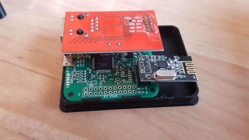
      can it be that the nano has too little power (+5V) for the NRF and W5100 when I feed it via USB?

      posted in Hardware
      rafael156
      rafael156
    • RE: not working Ethernet Gateway (sensebender and/or nano gateway)

      ok, i tried again to get the nano ethernet GW running with the following sketch, with partial success: the fritzbox recognizes the ip address. But with the MYSController or Openhab I still can't establish a connection (connection refused).:

      /*
       * The MySensors Arduino library handles the wireless radio link and protocol
       * between your home built sensors/actuators and HA controller of choice.
       * The sensors forms a self healing radio network with optional repeaters. Each
       * repeater and gateway builds a routing tables in EEPROM which keeps track of the
       * network topology allowing messages to be routed to nodes.
       *
       * Created by Henrik Ekblad <henrik.ekblad@mysensors.org>
       * Copyright (C) 2013-2018 Sensnology AB
       * Full contributor list: https://github.com/mysensors/MySensors/graphs/contributors
       *
       * Documentation: http://www.mysensors.org
       * Support Forum: http://forum.mysensors.org
       *
       * This program is free software; you can redistribute it and/or
       * modify it under the terms of the GNU General Public License
       * version 2 as published by the Free Software Foundation.
       *
       *******************************
       *
       * REVISION HISTORY
       * Version 1.0 - Henrik EKblad
       * Contribution by a-lurker and Anticimex,
       * Contribution by Norbert Truchsess <norbert.truchsess@t-online.de>
       * Contribution by Tomas Hozza <thozza@gmail.com>
       *
       *
       * DESCRIPTION
       * The EthernetGateway sends data received from sensors to the ethernet link.
       * The gateway also accepts input on ethernet interface, which is then sent out to the radio network.
       *
       * The GW code is designed for Arduino 328p / 16MHz.  ATmega168 does not have enough memory to run this program.
       *
       * LED purposes:
       * - To use the feature, uncomment MY_DEFAULT_xxx_LED_PIN in the sketch below
       * - RX (green) - blink fast on radio message received. In inclusion mode will blink fast only on presentation received
       * - TX (yellow) - blink fast on radio message transmitted. In inclusion mode will blink slowly
       * - ERR (red) - fast blink on error during transmission error or receive crc error
       *
       * See http://www.mysensors.org/build/ethernet_gateway for wiring instructions.
       *
       */
      
      // Enable debug prints to serial monitor
      #define MY_DEBUG
      
      // Enable and select radio type attached
      #define MY_RADIO_RF24
      //#define MY_RADIO_NRF5_ESB
      //#define MY_RADIO_RFM69
      //#define MY_RADIO_RFM95
      
      // Enable gateway ethernet module type
      #define MY_GATEWAY_W5100
      //#define MY_GATEWAY_MAX_CLIENTS  3
      
      // W5100 Ethernet module SPI enable (optional if using a shield/module that manages SPI_EN signal)
      //#define MY_W5100_SPI_EN 4
      
      // Enable Soft SPI for NRF radio (note different radio wiring is required)
      // The W5100 ethernet module seems to have a hard time co-operate with
      // radio on the same spi bus.
      #if !defined(MY_W5100_SPI_EN) && !defined(ARDUINO_ARCH_SAMD)
      #define MY_SOFTSPI
      #define MY_SOFT_SPI_SCK_PIN 14
      #define MY_SOFT_SPI_MISO_PIN 16
      #define MY_SOFT_SPI_MOSI_PIN 15
      #endif
      
      // When W5100 is connected we have to move CE/CSN pins for NRF radio
      #ifndef MY_RF24_CE_PIN
      #define MY_RF24_CE_PIN 5
      #endif
      #ifndef MY_RF24_CS_PIN
      #define MY_RF24_CS_PIN 6
      #endif
      
      // Enable UDP communication
      //#define MY_USE_UDP  // If using UDP you need to set MY_CONTROLLER_IP_ADDRESS below
      
      // Enable MY_IP_ADDRESS here if you want a static ip address (no DHCP)
      #define MY_IP_ADDRESS 192,168,1,110
      
      // If using static ip you can define Gateway and Subnet address as well
      #define MY_IP_GATEWAY_ADDRESS 192,168,1,1
      #define MY_IP_SUBNET_ADDRESS 255,255,255,0
      
      // Renewal period if using DHCP
      //#define MY_IP_RENEWAL_INTERVAL 60000
      
      // The port to keep open on node server mode / or port to contact in client mode
      #define MY_PORT 5003
      
      // Controller ip address. Enables client mode (default is "server" mode).
      // Also enable this if MY_USE_UDP is used and you want sensor data sent somewhere.
      //#define MY_CONTROLLER_IP_ADDRESS 192, 168, 178, 254
      
      // The MAC address can be anything you want but should be unique on your network.
      // Newer boards have a MAC address printed on the underside of the PCB, which you can (optionally) use.
      // Note that most of the Arduino examples use  "DEAD BEEF FEED" for the MAC address.
      //#define MY_MAC_ADDRESS 0x7F, 0x24, 0xCE, 0x40, 0x46, 0x44
      #define MY_MAC_ADDRESS 0xDE, 0xAD, 0xBE, 0xEF, 0xFE, 0xED
      
      // Enable inclusion mode
      #define MY_INCLUSION_MODE_FEATURE
      // Enable Inclusion mode button on gateway
      //#define MY_INCLUSION_BUTTON_FEATURE
      // Set inclusion mode duration (in seconds)
      #define MY_INCLUSION_MODE_DURATION 60
      // Digital pin used for inclusion mode button
      //#define MY_INCLUSION_MODE_BUTTON_PIN  3
      
      // Set blinking period
      #define MY_DEFAULT_LED_BLINK_PERIOD 300
      
      // Flash leds on rx/tx/err
      // Uncomment to override default HW configurations
      //#define MY_DEFAULT_ERR_LED_PIN 7  // Error led pin
      //#define MY_DEFAULT_RX_LED_PIN  8  // Receive led pin
      //#define MY_DEFAULT_TX_LED_PIN  9  // Transmit led pin
      
      #if defined(MY_USE_UDP)
      #include <EthernetUdp.h>
      #endif
      #include <Ethernet.h>
      #include <MySensors.h>
      
      void setup()
      {
      	// Setup locally attached sensors
      }
      
      void presentation()
      {
      	// Present locally attached sensors here
      }
      
      void loop()
      {
      	// Send locally attached sensors data here
      }


      the log of it is two posts before.
      For the W5100 does "MO"=MOSI and "MI"=MISO?
      Bild Text
      What am I doing wrong? has one of you already built a nano with W5100?

      posted in Hardware
      rafael156
      rafael156
    • RE: not working Ethernet Gateway (sensebender and/or nano gateway)

      ok, the log of the nano ethernet gateway is as follows:
      0 MCO:BGN:INIT GW,CP=RNNGA---,REL=255,VER=2.3.1<\n>
      4 TSM:INIT<\n>
      5 TSF:WUR:MS=0<\n>
      11 TSM:INIT:TSP OK<\n>
      13 TSM:INIT:GW MODE<\n>
      15 TSM:READY:ID=0,PAR=0,DIS=0<\n>
      17 MCO:REG:NOT NEEDED<\n>
      642 GWT:TIN:IP=255.255.255.255<\n>
      1644 MCO:BGN:STP<\n>
      1645 MCO:BGN:INIT OK,TSP=1<\n>
      1648 TSM:READY:NWD REQ<\n>
      1685 TSF:MSG:SEND,0-0-255-255,s=255,c=3,t=20,pt=0,l=0,sg=0,ft=0,st=OK:<\n>
      900006 TSF:SAN:OK<\n>

      is it possible, that the w5100 draws too much current for the nano?i connected only USB

      posted in Hardware
      rafael156
      rafael156
    • RE: not working Ethernet Gateway (sensebender and/or nano gateway)

      @tbowmo said in not working Ethernet Gateway (sensebender and/or nano gateway):

      standard cortex swd pinout

      ok, unfortunately i have never used a swd debugger before. i read on the internet that the JTAGICE mkII can program the cortex mo+. i have that here. is it really possible?
      with the ch341 i currently have the problem that windows does not recognize the driver after an update. before it was always possible. i have the driver from http://www.wch.cn/download/CH341SER_EXE.html.
      all my arduino nanos are no longer recognized.

      posted in Hardware
      rafael156
      rafael156
    • not working Ethernet Gateway (sensebender and/or nano gateway)

      Hello!

      I have the problem that I cannot use an ethernet gateway at the moment. I have a sensebender board, which can't be programmed any more. I exchanged the Atmel SAMD21 and have to program it now.
      Can you tell me with which programmer and at which pins on the sensebender board I have to program the processor?

      and my second question is:
      i tried to build an ethernet gateway with an arduino(clone) nano + nrf+w5100 (https://www.mysensors.org/view/178#enc28j60-ethernet-module). i did everything as described in the manual, but neither openhab nor MYSController can connect to the gateway. LEDs from the nano and w5100 light up/flash. does anyone know why this could be? is the normal usb-connection of the nano sufficient for the power supply?

      posted in Hardware
      rafael156
      rafael156
    • RE: Sensebender GW update: unknown device

      Any ideas?

      posted in Hardware
      rafael156
      rafael156
    • Sensebender GW update: unknown device

      Hello dear Comunity!

      I wanted to update my sensebender GW from 2.2 to 2.3 yesterday. after some updates windows couldn't recognize the board anymore (see screenshot). so i can't establish any communication anymore. When I installed 2.2 half a year ago, everything worked.
      On the board itself, the red LED flashes from time to time. the yellow and green LEDs light up permanently.
      can i assume that the cpu is defective?

      My system:
      Arduino IDE 1.8.5, Windows 10

      Device Manager

      Device Manager

      posted in Hardware
      rafael156
      rafael156
    • RE: [SOLVED] MYSBootloader FOTA Update hangs on ProMini-3V-8MHz (reboot problem)

      ok, Thanks at all!
      You helped me find the mistake!
      it was actually because the node could not receive commands because there was a "sleep()" hidden somewhere in each sketch. after I searched all sketches thoroughly and replaced them with "wait()", everything runs without problems:

      /**
       * The MySensors Arduino library handles the wireless radio link and protocol
       * between your home built sensors/actuators and HA controller of choice.
       * The sensors forms a self healing radio network with optional repeaters. Each
       * repeater and gateway builds a routing tables in EEPROM which keeps track of the
       * network topology allowing messages to be routed to nodes.
       *
       * Created by Henrik Ekblad <henrik.ekblad@mysensors.org>
       * Copyright (C) 2013-2015 Sensnology AB
       * Full contributor list: https://github.com/mysensors/Arduino/graphs/contributors
       *
       * Documentation: http://www.mysensors.org
       * Support Forum: http://forum.mysensors.org
       *
       * This program is free software; you can redistribute it and/or
       * modify it under the terms of the GNU General Public License
       * version 2 as published by the Free Software Foundation.
       *
       *******************************
       *
       * REVISION HISTORY
       * Version 1.0: Henrik EKblad
       * Version 1.1 - 2016-07-20: Converted to MySensors v2.0 and added various improvements - Torben Woltjen (mozzbozz)
       * 
       * DESCRIPTION
       * This sketch provides an example of how to implement a humidity/temperature
       * sensor using a DHT11/DHT-22.
       *  
       * For more information, please visit:
       * http://www.mysensors.org/build/humidity
       * 
       */
      
      // Enable debug prints
      #define MY_DEBUG
      
      // Enable and select radio type attached 
      #define MY_RADIO_NRF24
      //#define MY_RADIO_RFM69
      //#define MY_RS485
       
      #include <SPI.h>
      #include <MySensors.h>  
      #include <DHT.h>
      
      // Set this to the pin you connected the DHT's data pin to
      #define DHT_DATA_PIN 3
      
      // Set this offset if the sensor has a permanent small offset to the real temperatures
      #define SENSOR_TEMP_OFFSET 0
      
      // Sleep time between sensor updates (in milliseconds)
      // Must be >1000ms for DHT22 and >2000ms for DHT11
      static const uint64_t UPDATE_INTERVAL = 60000;
      
      // Force sending an update of the temperature after n sensor reads, so a controller showing the
      // timestamp of the last update doesn't show something like 3 hours in the unlikely case, that
      // the value didn't change since;
      // i.e. the sensor would force sending an update every UPDATE_INTERVAL*FORCE_UPDATE_N_READS [ms]
      static const uint8_t FORCE_UPDATE_N_READS = 10;
      
      #define CHILD_ID_HUM 0
      #define CHILD_ID_TEMP 1
      
      float lastTemp;
      float lastHum;
      uint8_t nNoUpdatesTemp;
      uint8_t nNoUpdatesHum;
      bool metric = true;
      
      MyMessage msgHum(CHILD_ID_HUM, V_HUM);
      MyMessage msgTemp(CHILD_ID_TEMP, V_TEMP);
      DHT dht;
      
      
      void presentation()  
      { 
        // Send the sketch version information to the gateway
        sendSketchInfo("TemperatureAndHumidity", "1.1");
        
        // Register all sensors to gw (they will be created as child devices)
        present(CHILD_ID_HUM, S_HUM);
        present(CHILD_ID_TEMP, S_TEMP);
        
        metric = getControllerConfig().isMetric;
      }
      
      
      void setup()
      {
        dht.setup(DHT_DATA_PIN); // set data pin of DHT sensor
        if (UPDATE_INTERVAL <= dht.getMinimumSamplingPeriod()) {
          Serial.println("Warning: UPDATE_INTERVAL is smaller than supported by the sensor!");
        }
        // Sleep for the time of the minimum sampling period to give the sensor time to power up
        // (otherwise, timeout errors might occure for the first reading)
        wait(dht.getMinimumSamplingPeriod());
      }
      
      
      void loop()      
      {  
        
        // Force reading sensor, so it works also after sleep()
        dht.readSensor(true);
        
        // Get temperature from DHT library
        float temperature = dht.getTemperature();
        if (isnan(temperature)) {
          Serial.println("Failed reading temperature from DHT!");
        } else if (temperature != lastTemp || nNoUpdatesTemp == FORCE_UPDATE_N_READS) {
          // Only send temperature if it changed since the last measurement or if we didn't send an update for n times
          lastTemp = temperature;
          if (!metric) {
            temperature = dht.toFahrenheit(temperature);
          }
          // Reset no updates counter
          nNoUpdatesTemp = 0;
          temperature += SENSOR_TEMP_OFFSET;
          send(msgTemp.set(temperature, 1));
      
          #ifdef MY_DEBUG
          Serial.print("T: ");
          Serial.println(temperature);
          #endif
        } else {
          // Increase no update counter if the temperature stayed the same
          nNoUpdatesTemp++;
        }
      
        // Get humidity from DHT library
        float humidity = dht.getHumidity();
        if (isnan(humidity)) {
          Serial.println("Failed reading humidity from DHT");
        } else if (humidity != lastHum || nNoUpdatesHum == FORCE_UPDATE_N_READS) {
          // Only send humidity if it changed since the last measurement or if we didn't send an update for n times
          lastHum = humidity;
          // Reset no updates counter
          nNoUpdatesHum = 0;
          send(msgHum.set(humidity, 1));
          
          #ifdef MY_DEBUG
          Serial.print("H: ");
          Serial.println(humidity);
          #endif
        } else {
          // Increase no update counter if the humidity stayed the same
          nNoUpdatesHum++;
        }
      
        // Sleep for a while to save energy
        //sleep(UPDATE_INTERVAL); 
        wait(UPDATE_INTERVAL);
      }
      
      void receive(){
      }
      

      However, I would suggest that the functions "wait()" and "smartsleep()" be mentioned in relation to the MySBootloader in a separate point under "https://www.mysensors.org/about/fota". Maybe under a chapter:

      1. Enabling FOTA in your sketch
        1.1 DualOptiboot only
        --> text as before
        1.2 MySBootloader
        --> ... use smartsleep() and wait() instead of sleep()...

      Summary:

      • fuse settings 8MHz external crystal:
      MYSBL.menu.frequency.MYSBL8=ATmega328 8Mhz ext MYSBootloader_1.3.0-rc.1
      MYSBL.menu.frequency.MYSBL8.build.f_cpu=8000000L
      MYSBL.menu.frequency.MYSBL8.upload.speed=57600
      MYSBL.menu.frequency.MYSBL8.bootloader.low_fuses=0xFF
      MYSBL.menu.frequency.MYSBL8.bootloader.high_fuses=0xD2
      MYSBL.menu.frequency.MYSBL8.bootloader.extended_fuses=0x06
      MYSBL.menu.frequency.MYSBL8.bootloader.unlock_bits=0x3F
      MYSBL.menu.frequency.MYSBL8.bootloader.lock_bits=0x0F
      MYSBL.menu.frequency.MYSBL8.bootloader.file=MySensors/MYSBootloader_8MHz.hex
      
      • if sensebender gateway is connected via usb, only one instance may access the gateway at a time, therefore "OpenHab" must be terminated first

      • do not use "sleep()" in the sketches. only "smartsleep()" or "wait()".
        use the current dev-branch from "https://github.com/mysensors/MySensorsBootloaderRF24

      posted in Troubleshooting
      rafael156
      rafael156
    • RE: [SOLVED] MYSBootloader FOTA Update hangs on ProMini-3V-8MHz (reboot problem)

      @Soloam i have checked fuse settings several times . i use the 8 mhz version. boards.txt see above .
      at burn process, arduino ide (1.6.13) gave me a warning about the fuses
      which fuses do you have?

      @gohan no, i didnt. but i have tried wait(), with no success. i will try smartsleep() today!

      posted in Troubleshooting
      rafael156
      rafael156
    • RE: [SOLVED] MYSBootloader FOTA Update hangs on ProMini-3V-8MHz (reboot problem)

      Yeah, right! That's the problem! But when I click on "reboot" on myscontroller, the node does not react to any command, i.e. reboot etc.
      is there a function that takes the command from myscontroller and executes it or do I have to implement it myself in the sketch?

      posted in Troubleshooting
      rafael156
      rafael156
    • RE: [SOLVED] MYSBootloader FOTA Update hangs on ProMini-3V-8MHz (reboot problem)

      @tekka Do you have an idea what´s wrong with the code? yesterday i have changed "sleep(UPDATE_INTERVAL);" to "wait(UPDATE_INTERVAL); " but bothing changed. Fota update or software reboot doesnt work.

      Are the fuses and the bootloader options (txt) correct?

      posted in Troubleshooting
      rafael156
      rafael156
    • RE: [SOLVED] MYSBootloader FOTA Update hangs on ProMini-3V-8MHz (reboot problem)

      this is the current dht-sketch from mysensors-examples:

      /**
       * The MySensors Arduino library handles the wireless radio link and protocol
       * between your home built sensors/actuators and HA controller of choice.
       * The sensors forms a self healing radio network with optional repeaters. Each
       * repeater and gateway builds a routing tables in EEPROM which keeps track of the
       * network topology allowing messages to be routed to nodes.
       *
       * Created by Henrik Ekblad <henrik.ekblad@mysensors.org>
       * Copyright (C) 2013-2015 Sensnology AB
       * Full contributor list: https://github.com/mysensors/Arduino/graphs/contributors
       *
       * Documentation: http://www.mysensors.org
       * Support Forum: http://forum.mysensors.org
       *
       * This program is free software; you can redistribute it and/or
       * modify it under the terms of the GNU General Public License
       * version 2 as published by the Free Software Foundation.
       *
       *******************************
       *
       * REVISION HISTORY
       * Version 1.0: Henrik EKblad
       * Version 1.1 - 2016-07-20: Converted to MySensors v2.0 and added various improvements - Torben Woltjen (mozzbozz)
       * 
       * DESCRIPTION
       * This sketch provides an example of how to implement a humidity/temperature
       * sensor using a DHT11/DHT-22.
       *  
       * For more information, please visit:
       * http://www.mysensors.org/build/humidity
       * 
       */
      
      // Enable debug prints
      #define MY_DEBUG
      
      // Enable and select radio type attached 
      #define MY_RADIO_NRF24
      //#define MY_RADIO_RFM69
      //#define MY_RS485
       
      #include <SPI.h>
      #include <MySensors.h>  
      #include <DHT.h>
      
      // Set this to the pin you connected the DHT's data pin to
      #define DHT_DATA_PIN 3
      
      // Set this offset if the sensor has a permanent small offset to the real temperatures
      #define SENSOR_TEMP_OFFSET 0
      
      // Sleep time between sensor updates (in milliseconds)
      // Must be >1000ms for DHT22 and >2000ms for DHT11
      static const uint64_t UPDATE_INTERVAL = 60000;
      
      // Force sending an update of the temperature after n sensor reads, so a controller showing the
      // timestamp of the last update doesn't show something like 3 hours in the unlikely case, that
      // the value didn't change since;
      // i.e. the sensor would force sending an update every UPDATE_INTERVAL*FORCE_UPDATE_N_READS [ms]
      static const uint8_t FORCE_UPDATE_N_READS = 10;
      
      #define CHILD_ID_HUM 0
      #define CHILD_ID_TEMP 1
      
      float lastTemp;
      float lastHum;
      uint8_t nNoUpdatesTemp;
      uint8_t nNoUpdatesHum;
      bool metric = true;
      
      MyMessage msgHum(CHILD_ID_HUM, V_HUM);
      MyMessage msgTemp(CHILD_ID_TEMP, V_TEMP);
      DHT dht;
      
      
      void presentation()  
      { 
        // Send the sketch version information to the gateway
        sendSketchInfo("TemperatureAndHumidity", "1.1");
        
        // Register all sensors to gw (they will be created as child devices)
        present(CHILD_ID_HUM, S_HUM);
        present(CHILD_ID_TEMP, S_TEMP);
        
        metric = getControllerConfig().isMetric;
      }
      
      
      void setup()
      {
        dht.setup(DHT_DATA_PIN); // set data pin of DHT sensor
        if (UPDATE_INTERVAL <= dht.getMinimumSamplingPeriod()) {
          Serial.println("Warning: UPDATE_INTERVAL is smaller than supported by the sensor!");
        }
        // Sleep for the time of the minimum sampling period to give the sensor time to power up
        // (otherwise, timeout errors might occure for the first reading)
        sleep(dht.getMinimumSamplingPeriod());
      }
      
      
      void loop()      
      {  
        // Force reading sensor, so it works also after sleep()
        dht.readSensor(true);
        
        // Get temperature from DHT library
        float temperature = dht.getTemperature();
        if (isnan(temperature)) {
          Serial.println("Failed reading temperature from DHT!");
        } else if (temperature != lastTemp || nNoUpdatesTemp == FORCE_UPDATE_N_READS) {
          // Only send temperature if it changed since the last measurement or if we didn't send an update for n times
          lastTemp = temperature;
          if (!metric) {
            temperature = dht.toFahrenheit(temperature);
          }
          // Reset no updates counter
          nNoUpdatesTemp = 0;
          temperature += SENSOR_TEMP_OFFSET;
          send(msgTemp.set(temperature, 1));
      
          #ifdef MY_DEBUG
          Serial.print("T: ");
          Serial.println(temperature);
          #endif
        } else {
          // Increase no update counter if the temperature stayed the same
          nNoUpdatesTemp++;
        }
      
        // Get humidity from DHT library
        float humidity = dht.getHumidity();
        if (isnan(humidity)) {
          Serial.println("Failed reading humidity from DHT");
        } else if (humidity != lastHum || nNoUpdatesHum == FORCE_UPDATE_N_READS) {
          // Only send humidity if it changed since the last measurement or if we didn't send an update for n times
          lastHum = humidity;
          // Reset no updates counter
          nNoUpdatesHum = 0;
          send(msgHum.set(humidity, 1));
          
          #ifdef MY_DEBUG
          Serial.print("H: ");
          Serial.println(humidity);
          #endif
        } else {
          // Increase no update counter if the humidity stayed the same
          nNoUpdatesHum++;
        }
      
        // Sleep for a while to save energy
        sleep(UPDATE_INTERVAL); 
      }
      
      posted in Troubleshooting
      rafael156
      rafael156
    • RE: [SOLVED] MYSBootloader FOTA Update hangs on ProMini-3V-8MHz (reboot problem)

      here's what I've been trying on arduino 328P-8MHz XTAL-3v3:
      fuse settings from development branch(only to external xtal changed):

      MYSBL.menu.frequency.MYSBL8=ATmega328 8Mhz ext MYSBootloader_1.3.0-rc.1
      MYSBL.menu.frequency.MYSBL8.build.f_cpu=8000000L
      MYSBL.menu.frequency.MYSBL8.upload.speed=57600
      MYSBL.menu.frequency.MYSBL8.bootloader.low_fuses=0xFF
      MYSBL.menu.frequency.MYSBL8.bootloader.high_fuses=0xD2
      MYSBL.menu.frequency.MYSBL8.bootloader.extended_fuses=0x06
      MYSBL.menu.frequency.MYSBL8.bootloader.unlock_bits=0x3F
      MYSBL.menu.frequency.MYSBL8.bootloader.lock_bits=0x0F
      MYSBL.menu.frequency.MYSBL8.bootloader.file=MySensors/MYSBootloader_8MHz.hex
      

      then i burned the bootloader from https://github.com/mysensors/MySensorsBootloaderRF24/blob/development/hex/MYSBootloader_8MHz.hex
      and got warnings from arduino IDE:

      avrdude: WARNING: invalid value for unused bits in fuse "lock", should be set to 1 according to datasheet
      This behaviour is deprecated and will result in an error in future version
      You probably want to use 0xff instead of 0x3f (double check with your datasheet first).
      avrdude: WARNING: invalid value for unused bits in fuse "efuse", should be set to 1 according to datasheet
      This behaviour is deprecated and will result in an error in future version
      You probably want to use 0xfe instead of 0x06 (double check with your datasheet first).
      avrdude: WARNING: invalid value for unused bits in fuse "lock", should be set to 1 according to datasheet
      This behaviour is deprecated and will result in an error in future version
      You probably want to use 0xcf instead of 0x0f (double check with your datasheet first).
      

      Then the first firmware after flashing the bootloader:

      https://ibb.co/gbQ7Sd

      serial communication works, but with baud 115200. shouldn't this be 57600 at 8MHz?
      https://ibb.co/cxpqfy

      a manual restart of the node does nothing...
      https://ibb.co/e7bp7d

      after i hard-reset, the node is restarting...
      https://ibb.co/jTxMnd

      warum funktioniert der software reboot nicht? und warum hat der node eine baud rate von 115200 statt 57600 nach aktuellem dev.branch?

      posted in Troubleshooting
      rafael156
      rafael156
    • RE: [SOLVED] MYSBootloader FOTA Update hangs on ProMini-3V-8MHz (reboot problem)

      this has now worked:

      • in the sketch you don't have to activate the fota update in the mysbootloader
      • the last MYSBootloader 1.3.0-rc.1 works

      the next problem is:
      if the node has no sketch, the node boots constantly into the bootloader and can load every sketch per fota update.
      as soon as the node has a sketch and is rebooted by the myscontroller, the node is only restarted by software/watchdog and apparently does not jump into the bootloader. thus it cannot load a new sketch.
      Only if I reboot the node manually, the fota update works.

      The only problem is the soft-reset, which does not work as expected.

      Is there a way to reboot the Atmega328p like I do with the manual button?
      Why does the watchdog/ soft-reset not work?

      posted in Troubleshooting
      rafael156
      rafael156
    • RE: [SOLVED] MYSBootloader FOTA Update hangs on ProMini-3V-8MHz (reboot problem)

      thanks for the info!
      i thought you only needed it for DualOptiboot. I read it here:
      https://www.mysensors.org/about/fota#enabling-fota-in-your-sketch-dualoptiboot-only

      posted in Troubleshooting
      rafael156
      rafael156
    • RE: [SOLVED] MYSBootloader FOTA Update hangs on ProMini-3V-8MHz (reboot problem)

      Thanks for the answer! I found the error yesterday:
      I had OpenHab running in the background on the Linux system with the Sensebender Gateway (as USB). As a result, it appears that the gateway was "occupied" for a time. After I closed Openhab, I was able to perform a FOTA update without errors.

      However, after I have uploaded the sketch "passive node", I cannot upload another sketch. After the first upload, the node executes its code normally and does not receive a new sketch anymore.

      Does the sketch have to be programmed for fota updates? Maybe with a setting?

      I have MYSController Version 1.0.0.3316

      posted in Troubleshooting
      rafael156
      rafael156
    • RE: [SOLVED] MYSBootloader FOTA Update hangs on ProMini-3V-8MHz (reboot problem)

      Can anyone help? Do i have to flash the Arduino with a USBasp?

      posted in Troubleshooting
      rafael156
      rafael156
    • [SOLVED] MYSBootloader FOTA Update hangs on ProMini-3V-8MHz (reboot problem)

      Hello!

      I have a Pro Mini 328P 3.3V 8MHz clone with external quartz on which I wanted to install the MYSBootloader.
      The Arduino is as follows:
      https://de.aliexpress.com/item/ProMini-ATmega328P-3-3V-Compatible-for-Arduino-Pro-Mini/32525927539.html?spm=a2g0x.search0104.3.120.62c938ebDXquOj&ws_ab_test=searchweb0_0,searchweb201602_2_10320_10152_10321_10065_10151_10344_10068_10342_10547_10343_10322_10340_10548_10341_10193_10194_10084_10083_10618_10304_10307_10302_10180_10313_10059_10184_10534_100031_10319_1010101010103_10627_10634_1053searchweb201603_25,ppcSwitch_5&algo_expid=f9abed72-8c7f-41ab-9222-8e1f1c07db75-17&algo_pvid=f9abed72-8c7f-41ab-9222-8e1f1c07db75&priceBeautifyAB=0

      Fuse settings are as follows:
      low_fuses=0xFF
      high_fuses=0xD2
      extended_fuses=0x06

      I have the MYSBootloader here:
      https://github.com/mysensors/MySensorsBootloaderRF24/blob/master -> Branch:Master and MYSBootloader.hex

      I also tried:
      https://github.com/mysensors/MySensorsBootloaderRF24/tree/UpdateBoardFiles -> Branch: UpdateBoardFiles and /hex/MYSBootloader_8MHz.hex

      I have the Sensebender Gateway on a Linux server.
      All pins of the NRF24L01+ are connected to the Arduino.
      I use MySensors 2.2.0.

      I programmed the fuses, the hex files mentioned above and a sketch with the mySmartUSBLight Programmer without Arduino IDE. As an example sketch I took the "Mysensor passive node".

      Now to the problem:
      When I try to start a FOTA update to the node (ID100) with the MYSController (https://www.mysensors.org/controller/myscontroller), the following comes in the debug log of the MYSController:
      "[Firmware config response] 01000..."

      The status of the node indicates "FW updating 1%". Even after an hour of waiting, nothing happens. Even a reboot via the MYController does not work independently of the FOTA update.
      It seems that the bootloader does not work.

      I've been trying for hours, but I haven't found the error.
      Can you help me, please?

      posted in Troubleshooting
      rafael156
      rafael156