Nope but winter season is starting again so I have some spare time not being "outside" so I will be starting this project back up
Posts made by sj44k
-
RE: Building an Ethernet Gateway on an Arduino Mega
-
RE: Building an Ethernet Gateway on an Arduino Mega
@barduino
Can you help me out here, I do not get your remark :
So first step was to connect the wireless module to the ICSPAs my Ethershield is using this, how will this work together with the radio and the ethershield connected to the same pins ?
My guess I am not getting exactly what you mean. -
RE: Building an Ethernet Gateway on an Arduino Mega
:)Hunt for the red october classic
-
RE: Building an Ethernet Gateway on an Arduino Mega
I use the ethernet gateway example of this site, and I am absolutely 100% sure it does reply on ping as when I use the same code on my UNO with the same shield, I do get an reply.
When switching the shield to the MEGA, and placing the pins on 14 15 and 16 nothing happens.Do you get a ping ?
-
RE: Building an Ethernet Gateway on an Arduino Mega
@MSchmidke I am going to try this asap and post my findings .. but sir .. could you please share with me (and the rest of the world ) how did you find out about these pins ? I love solutions but I crave to understand WHY
But still if this works you deserve my everlasting respect for finding it and sharing !
@Heinz
Are you using an Arduino MEGA ? I guess you are not.[one hour later]
Ok figures that you choose 14/15/16 on the mega the RF24config.h states :` const uint8_t SOFT_SPI_MISO_PIN = 16; const uint8_t SOFT_SPI_MOSI_PIN = 15; const uint8_t SOFT_SPI_SCK_PIN = 14;
But having that said I still am not getting a reply on a ping when I ping the ethershield .. so we are close .. but not there yet
I do get the
0;0;3;0;14;Gateway startup complete.
So that's further than I've been so far ..
-
RE: Programming the Arduino Pro Mini 3.3V
@tejo
What do you propose exactly ? An ISP is needed to do the bootloader burn. But as the BLINK sketch the supplier loaded the bootloader is working right otherwise the system would not be able to run the BLINK sketch.Could you be a bit more specific ? I would still love to get this to work
-
RE: Programming the Arduino Pro Mini 3.3V
Well so far no luck, and someone I know has exact the same issues, bought the boards from another seller (batch of 10) but the boards look 100% alike as fare my naked eye can tell.
We did a lot of different experiments, which where all 100% successful on the 5v version, even with the FDTI on 3,3 volts (fluke multimeter checked) the 5v versions behaves perfect, the 3,3volts no luck whatsoever.
My guess is that it's either a bad batch or completely fake.
Took me too much time so might experiment a bit with it.Will order a different type to see if this a bad batch.
If anyone has a supplier (link) they received working 3,3v Pro Mini board from ? This would be very valuable information
-
RE: Help with ethernet GW
It will not work with this IP address, and you have to put an IP address in manual in your sketch (DHCP does not work)
The Ethernet sketch example shows at lines 64 to 69:IPAddress myIp (192, 168, 178, 66); // Configure your static ip-address here COMPILE ERROR HERE? Use Arduino IDE 1.5.7 or later! // The MAC address can be anything you want but should be unique on your network. // Newer boards have a MAC address printed on the underside of the PCB, which you can (optionally) use. // Note that most of the Ardunio examples use "DEAD BEEF FEED" for the MAC address. byte mac[] = { 0xDE, 0xAD, 0xBE, 0xEF, 0xFE, 0xED }; // DEAD BEEF FEED
So IP: 192.168.178.66
MAC : DEAD BEEF FEED"Did you use this sketch or can you try this one and post your results ?
-
RE: Programming the Arduino Pro Mini 3.3V
@grzegorzc
You are correct I need to do the manual reset I tried (at least 30 times) , but as stated above unsuccessful.I use the same procedure for the 5v version and I have a success rate of 95%. So I do not get it.
I will get my hands on an FDTI with DTR Line this week hope this will solve my issue but current setup seems unsuccessful with the 3,3v Pro Mini.
[update]I worked yesterday with this FTDI USB to TTL Serial Adapter Module for Arduino Mini Port 3.3V 5V and still no luck.
Same behavior all over, my 5v arduino pro mini boards worked like a charm, but when I changed the arduino boards to this 3,3v Arduino pro mini board no luck what so ever.
Jumper is on 3,3v and Arduino runs the pre programmed BLINK sketch fine, but no way on earth I am getting it programmed with another (not even an empty) sketch.Anyone ?
-
RE: Programming the Arduino Pro Mini 3.3V
So with my USB to Serial converter it should work ? So the Arduino Module is defect ?
-
Programming the Arduino Pro Mini 3.3V
Being new to the whole Arduino world, I seem to make a few dumb assumptions and I really am not able to easily find an answer on google. So sorry for bothering you but I am having a nasty issue.
Trying to minimize my sensors I recently bought a 5v and 3,3v arduino pro mini (both one as an experiment)
Programming the 5v version works like a charm using my PL2303 USB To RS232 TTL Converter Adapter which I used for some other project I did.As this little baby has a 3,3v I asumed (here we go ) connecting the 3,3v Arduino pro mini to this when using the 3,3v Pin instead of the 5v pin I normaly use should work.
But it does not, the 3,3v Arduino powers on just fine and starts running the blink example it got shipped with. But using the same procedure as the 5v Arduino pro mini to program its (which works fine) this little thing is just not getting the communication on.
So can someone tell me if I am just unlucky and the procedure I use should work and I might have an deffective 3,3v Arduino or that I really need to buy the FTDI Basic Breakout USB-TTL 6 PIN 3.3/5V to get this baby programmed.
Thanks for helping me out.
-
RE: Building an Ethernet Gateway on an Arduino Mega
I am still in the process of fixing this, is there anyone who can explain me why this is not working ?
According to all the info I could find it that all I/O pins on the UNO are available on the MEGA, only MEGA has more pins available.So I still have no idea why this sketch is not working on my Mega but is on my UNO with the exact same EtherShield (as I own only one)
-
RE: [security] Introducing signing support to MySensors
@Anticimex
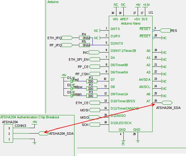
Thanks for that info, to me it is clear that depending on the used pin in the software one should connect the ATSHA204A corresponding with the software.
Picture does show you being correct how simple it really is to embed the ATSHA204A hardware in the total setup. -
RE: [security] Introducing signing support to MySensors
@mainali
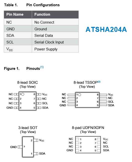
Does this help you? Sometimes a few pics say more than a 1000 wordsI made this pic from the Datasheet giving you the pinouts of the ATSHA204A in all known housings.
And the way how to connect is (shamelessly stolen from the GW design of @Anticimex )
-
RE: Arduino Mega + RelayWithButtonActuator sketch
As you can see in your messages the code "st=fail" means there is an issue.
Did you install the decoupling capacitor like mentioned hereAs @hek mentioned the 3v3v output of a mega is (and I quote) "super junk" this might be the cause of your issue, the decoupling capacitor might just solve this (by the way it is always advisable to install these) but also the usage of a step down regulator so you can use the 5v rail to feed the radio could be necessary (in combination with the capacitor).
I have had a Mega + radio running on it's 3v3 feed with only the capacitor installed but all depends of the quality of your components so hard to say that this is always a winning combination, but that would be my way to go.
-
RE: Building an Ethernet Gateway on an Arduino Mega
@Heinz
I guess I did not make myself perfectly clear as I allready had this information and my W5100 shield is using these pins from the pin 6 pin header in the middle of the board (check the red circle)
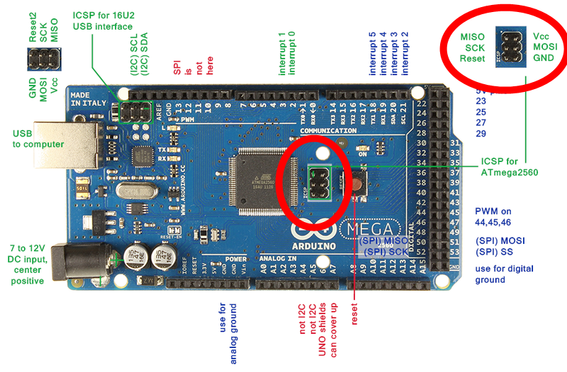
So I am wondering if these pins are addressed as the same pin numbers on the MEGA as on the UNO (thus making the sketches compatible).
I am doubting this as I had some issues with this during building a temp sensor designed for an Uno (or Mini) on the same Mega (check also the first link in my initial post).The Radio in the Ethernet Gateway is addressed via SoftSPI, and is referred to use :
A2 MISO
A1 MOSI
A0 SCK
6 CSN
5 CEMy guess us that to address the Analogue and digital pins (A0, A1, A2, 5 and 6 ) on an Arduino Mega I need to change some code / pin referals. to get this working. Now I still get :
0;0;3;0;9;check wiresMy Radio is currently connected to all these pins (A0, A1, A2, 5 and 6 ) located all on the W5100 shield, so I did not change anything from the UNO configuration (which is working) but it's not working on the Mega
After finding the Pin alias sheet for the UNO Clearing up the pins 16,15 and 14 referring to A0,A1,and A2 if found another sheet and according to this sheet I changed the following in my RF24_config.h ( As I hoped that according to this sheet A0,A1 and A2 labeled on the MEGA are corresponding with Digital Pins 56, 55 and 54
// change these pins to your liking // Default for Uno //const uint8_t SOFT_SPI_MISO_PIN = 16; //const uint8_t SOFT_SPI_MOSI_PIN = 15; //const uint8_t SOFT_SPI_SCK_PIN = 14; //const uint8_t SPI_MODE = 0; //MEGA CONFIG ? const uint8_t SOFT_SPI_MISO_PIN = 56; const uint8_t SOFT_SPI_MOSI_PIN = 55; const uint8_t SOFT_SPI_SCK_PIN = 54; const uint8_t SPI_MODE = 0;
But still no luck ..
-
Building an Ethernet Gateway on an Arduino Mega
I am trying to utilize all of my available Arduinos as best as I can, and having all sketches being developed on this site for the UNO my Arduino Mega seems to fit best in it's role as an Ethernet Gateway.
By this I am able to use my available UNO to do some more testing and playing around with the MySensor sketches without the need to modify my sketches like I did to do in the past
BUT, having that said this also exactly gives away my challenge :
Getting the Ethernet Gateway Sketch working on my Arduino Mega with a W5100 Ethernet Shield.
Issue is the pinout of a Mega's SPI interface is different than the UNO.So the sketch is working easily on my UNO, but changing the shield and uploading the same sketch to my MEGA results in a non working Ethernet Gateway (debug modes states : check wires)
(I did uncomment the #define SOFTSPI line in the RF24_Config.h by the way)Does anyone know which file / library I need to edit to change these pins ? I am using the W5100 shield not the module so I would prefer the shield installed as a is, and not use any jumper cables.
-
RE: Sensor board w/ liPo charger and fuel gauge +BMP180 +HTU21
@ceech Some impressive work you are pulling off here! I am also interested so keep us posted when you have it available !
-
RE: First sensor having radio issues
This most probably will be solved with the capacitors installed, here you can find exactly how, I and most people use 4,7u F which is enough.
http://www.mysensors.org/build/connect_radio -
RE: Multi Button Relay switch
That there is an issue in the radio communication, and most probably the reason why it's taking so long, as all the failed transmissions will be retransmitted.
Like mentioned above (and on the webpage) you should install the capacitors on the radio.Check the decoupling capacitor part of this page how to do this :
http://www.mysensors.org/build/connect_radio -
RE: UI 7 Ethernet Gateway Problem
@jeylites
Great, packet loss could have lots of reasons and are not necessarily related to your arduino / ethernet shield.
For example if the computer you are pinging via WiFi with lots of interference (so hard to judge / see as your signal indicator on the computer can still be indicating a good signal.So preferably you do all your tests connected via cable and on the same network device (your router), and as a reference you should try also to ping the router or another network device to check the connection from your computer to the network.
If these all show no packet loss, and a ping to your arduino does, than I agree with you the problem is caused by the ethershield.But make sure you use good network cables, they are not that expensive and easy to replace.
-
RE: Confused...sensors hook up to what?
Check the shop part of the mysensors.org website you will be amazed
Just be sure that you buy any Arduino with at least the ATmega328.I made a mistake buying the Arduino Mini with an ATmega168 micro controller (which is also available) but this has only half the amount of Flash Memory and EEPROM.
This makes it unusable for the sketches you will find on MySensors.org, and the price difference between the 2 types of Arduinos is a matter of cents.
-
RE: UI 7 Ethernet Gateway Problem
If you are not able to ping the gateway, you have an issue with either the network connection or the gateway self.
You can also debug your gateway by connect it via USB to your computer and use the serial monitoring function of Arduino IDE (on my windows machine that is activated via " Shift - Ctrl - M "Which components did you use for your gateway ?
As in which arduino and which Ethershield ? -
RE: "Smart" meter node
Also looking for this.
At this moment there is no example for this so if you could share your current sketch including your hardware setup I would really appriciate it !
I guess you invert the signal with a 7404 ? -
RE: Confused...sensors hook up to what?
@PaulTechGuy
You are able to combine several sensors on one Arduino but most examples you find on the MySensors site are based on 1 sensor per Arduino.
If you are able to write your own arduino sketches you should be able to manage to have more than one sensor per arduino depending on the type and need for input and outputs of the Arduino, but even the smallest Arduino has many input and output ports enabling you to have multiple / different sensors per Arduino.Having this said, and taking your ability of programming you should be able to figure this out.
Having an Raspbery Pi as an gateway has it's limmitations at this current moment so make sure you are aware of this.
I have got my Raspberry currently operational (check my postings for my struggle )My advise is buy a few Arduino's mini and at least 1 Arduino Nano or Mega and start playing with it, the learning curve is quite steep but it's so much fun
-
RE: Temperature Sensor example on Pro Mini ATmega168 not compiling
@reddy11
Forgive me my incompleteness, but I the ATmega168 is the processor on the Arduino Pro mini.
You can find the pro Mini with the ATmega168 and ATmega328 cpu, just buy the 328 costs 10cents more but gives you double the flash / memory and eeprom capicity (check the link in my initial post)@pjeterinfo
Thank you sir, makes sense, will try this tonight and revert.@GuyP
Yep exact my conclusion now, I just got mislead by the "wrong" link of the Arduino Pro Mini 5v at the shop section of this website, the aliexpress link pointed to a Arduino Pro mini Atmega168, this has been corrected to the right Atmega238 version (which is only 10 cents more expensive)[Few Hours later]
I disabled Debugging, and removed these lines 818 to line 830 from the file LowPower.cppif (bod == BOD_OFF) { #if defined __AVR_ATmega328P__ lowPowerBodOff(SLEEP_MODE_EXT_STANDBY); #else lowPowerBodOn(SLEEP_MODE_EXT_STANDBY); #endif } else { lowPowerBodOn(SLEEP_MODE_EXT_STANDBY); }
Sketch is now compiling, but less than 1% too big.
I will try an older version of the Mysensors library as current 1.4 is just a little bit too big.[And a few hours further]
I tried a lot but I am not able to get rid of this error :Sketch uses 14,366 bytes (100%) of program storage space. Maximum is 14,336 bytes. Global variables use 507 bytes (49%) of dynamic memory, leaving 517 bytes for local variables. Maximum is 1,024 bytes. processing.app.debug.RunnerException: Sketch too big; see http://www.arduino.cc/en/Guide/Troubleshooting#size for tips on reducing it.
Anyone an idea ? I disabled the debug in MyConfig.h but I'm not able to get it to compileYeah FIXED it
Won some space by edit line 53 and changed it to :// Fetch and round temperature to one decimal float temperature = static_cast<float>(static_cast<int> (sensors.getTempCByIndex(i) * 10.)) / 10.;
I will only need the sensor to have Celsius readouts and this gave me exactly enough room to compile this beautiful sketch
Sketch uses 14,308 bytes (99%) of program storage space. Maximum is 14,336 bytes. Global variables use 507 bytes (49%) of dynamic memory, leaving 517 bytes for local variables. Maximum is 1,024 bytes.
And it's official, the Temperature sketch is working I just build it successful with all components and it is communicating with my Raspberry PI
I'm quite curious how long it will run on a battery ! -
Temperature Sensor example on Pro Mini ATmega168 not compiling
The sketch in the example of the temperature sensor is not compiling for an Arduino Pro Mini ATmega168.
On the Codebender browser pluging I get error
There is not enough space!
And in my Arduino IDE on my machine I get error :
....Arduino\libraries\MySensors\utility\LowPower.cpp:828:3: note: in expansion of macro 'lowPowerBodOn'
lowPowerBodOn(SLEEP_MODE_EXT_STANDBY);
^
Error compiling.I am using the latest IDE 1.6.1 and the latest MySensor Libraries. All is compiling for my Arduino Mega and I also tested it for an Arduino Pro Mini ATmega328 which also works fine in both IDE as the Codebender pluging.
I am not sure (still learning) but I reckon the ATnega168 has not enough memory or storage to cope with this sketch.
If anyone has a tip it would be more than welcome !
I might be wrong but if I am not it would be nice for noobs like me to mention this somewhere in the article.
I see that the shop's link has just been adjusted as AliExpress link to the
Arduino Pro Mini Compatible 5V was pointing to the ATmega168 just an hour ago.
Might have been a slip up, no biggie it only costed me a few cents but I was hoping to build my remote temperature sensor and now I have to wait again a few weeks for the ATmega328 shipment.[EDIT]
Just checked most of the examples on the website here, and so for NONE of the sketches is compiling for the ATmega168.
-
RE: Raspberry GPIO NRF24l01+ make error
YEAH !
It works !! thanks for pointing me in the right direction !
Arduino needed the right scketch uploade (I messed so much with it I needed to go back which I just did)As a reference for all who are trying to get this to work.
Use this pinout for the RPI B+
Radio 1 grijs GND Rpi 25
Radio 2 paars 3v3 Rpi 17
Radio 3 blauw CE Rpi 22
Radio 4 groen CS Rpi 24
Radio 5 Geel SCK Rpi 23
Radio 6 oranje MOSI Rpi 19
Radio 7 Rood MISO Rpi 21Arduino Mega
Radio 1 GND Paars Arduino GND
Radio 2 3v3 Blauw Arduino 3,3v
Radio 3 CE Groen Arduino 48
Radio 4 CS Geel Arduino 49
Radio 5 SCK Oranje Arduino 52
Radio 6 MOSI Rood Arduino 51
Radio 7 MISO Bruin Arduino 50I used the Libs mentioned in the post above by Vladut Grecu :
https://github.com/mysensors/RaspberryI used this Temperature sketch :
http://www.mysensors.org/build/tempBefore I did got the Temp sketch operational I needed to clear my EEprom :
http://arduino.cc/en/Tutorial/EEPROMClear/* * EEPROM Clear * * Sets all of the bytes of the EEPROM to 0. * This example code is in the public domain. */ #include <EEPROM.h> void setup() { // write a 0 to all 512 bytes of the EEPROM for (int i = 0; i < 512; i++) EEPROM.write(i, 0); // turn the LED on when we're done digitalWrite(13, HIGH); } void loop() { }
Than we need to edit the sketch a bit due to the fact that the Rpi gateway DOES NOT hand out the Node ID's automaticly, and the Sketch is not Arduino Mega compatible so :
Set the Node ID manualy add
gw.begin(NULL,10,false);
Make sure the sketch is compatible with the Arduino MEGA pins (as published abover here)
Change Line 12 in the sketch :MySensor gw;
into
MySensor gw(48,49)
Than compile and hook everything up and upload the compiled sketch and start the Rpi (SPI enabled) and start
./PiGatewaySerialOutput should show on your Pi when you
Cat /dev/ttyMySensorsGatewayBig Thank you to @Vladut-Grecu !
-
RE: Raspberry GPIO NRF24l01+ make error
Tried that too, not working. But I now see why you asked that my output when starting PiGatewaySerial shows :
CE Pin = Custom GPIO25
So that needs to be harware pin 22
This picture helped a lot and makes now that I am 100% sure my Rpi is hooked up correctly.
:s: must be overseeing something realy simple / stupid .. :/s:
Guess it must be the Arduino Mega causing the issue, back to my drawingboard .. will keep you posted[edit]
Just found an interesting SPI reference picture for my Arduino Mega
My Pinout seems to be ok on the SPI side, just need to check CE / SE in regard to the scketch/libraries I am using.
Radio 1 GND Paars Arduino GND
Radio 2 3v3 Blauw Arduino 3,3v
Radio 3 CE Groen Arduino 48
Radio 4 CS Geel Arduino 49
Radio 5 SCK Oranje Arduino 52
Radio 6 MOSI Rood Arduino 51
Radio 7 MISO Bruin Arduino 50 -
RE: Raspberry GPIO NRF24l01+ make error
Checked the wires 5 times .. all looks well. CE is on pin 15
Arduino should also be ok, I get error messages (Check wires) when it's connected differently(Heres the Arduino mega pinout as I used it
http://forum.mysensors.org/topic/249/arduino-mega-sensor-shield-2/2 )I have an Uno ordered but at this moment I am stuck to 1 arduino
I do have an extra Pi which I could use ..By the way, where would I receive the information on my pi in this example (in case it would work)
?
in the screen where I started the
./PiGatewaySerialOr in a cat /dev/pts/1 ?
-
RE: Raspberry GPIO NRF24l01+ make error
Ok Radio was allready connected correctly, and I have the 4u7 capicitors installed.
So this is what I understood from your tips am I correct ?
git clone https://github.com/mysensors/Raspberry cd Rasberry make cd librf24-bcm make make install cd .. ./PiGatewaySerial Starting PiGatewaySerial... Protocol version - 1.4 Created PTY '/dev/pts/1' Gateway tty: /dev/ttyMySensorsGateway ================ SPI Configuration ================ CSN Pin = CE0 (PI Hardware Driven) CE Pin = Custom GPIO25 Clock Speed = 8 Mhz ================ NRF Configuration ================ STATUS = 0x0e RX_DR=0 TX_DS=0 MAX_RT=0 RX_P_NO=7 TX_FULL=0 RX_ADDR_P0-1 = 0xe7e7e7e7e7 0xc2c2c2c2c2 RX_ADDR_P2-5 = 0xff 0xc4 0xc5 0xc6 TX_ADDR = 0xe7e7e7e7e7 RX_PW_P0-6 = 0x00 0x00 0x20 0x00 0x00 0x00 EN_AA = 0x3b EN_RXADDR = 0x07 RF_CH = 0x4c RF_SETUP = 0x23 CONFIG = 0x0e DYNPD/FEATURE = 0x3f 0x06 Data Rate = 250KBPS Model = nRF24L01+ CRC Length = 16 bits PA Power = PA_LOW
So now I want to receive my Sensor info from my Arduino on my Raspbery.
I am using this build with a small addition on it as I am using an Arduino Mega so the pins are different :http://www.mysensors.org/build/temp
I Changed :
MySensor gw;
into
MySensor gw(48,49)
No I will do the figuring out about the node ID as I the tip about the auto ID does not work makes sense, the sensor now uses 0 and if I am correct that is the id of the gateway.
By the way to even get that part done I needed to clear the EEProm of the Arduino (found it somewhere on some forum )
I got the node secret also done now
I needed to set`gw.begin(NULL,10,false,11);
But still no communication / output on the Raspberry
Output on de Arduino is :
sensor started, id 10 send: 10-10-11-0 s=255,c=0,t=17,pt=0,l=5,st=fail:1.4.1 send: 10-10-11-0 s=255,c=3,t=6,pt=1,l=1,st=fail:11 send: 10-10-11-0 s=255,c=3,t=11,pt=0,l=18,st=fail:Temperature Sensor send: 10-10-11-0 s=255,c=3,t=12,pt=0,l=3,st=fail:1.0 send: 10-10-11-0 s=0,c=0,t=6,pt=0,l=5,st=fail:1.4.1 send: 10-10-11-0 s=0,c=1,t=0,pt=7,l=5,st=fail:68.7```
-
RE: Raspberry GPIO NRF24l01+ make error
Thank you ! Will try this tonight, what kind of input could I expect when I do a test on my Aruino ? I have a Arduino Mega as a test board at this moment.
Would a " Cat /dev/ttyMySensorsGateway' give me the output the Arduino is sending ?
Arduino is set up as the mysensor temperature sensor as published on the website and seems to be working (according to the serial monitor).SPI is enabled, but for the sake of being sure I will start with a new and fresh Raspbian installation on the PI tonight SPI enabled.
Again thanks for your reply ! I will post my findings.
-
RE: Raspberry GPIO NRF24l01+ make error
Could you please share where you found the information how to connect the Radio to your Raspberry ?
I am trying to get this to work for several day's but I am lost in all the different Information / Libraries and usage of different SPI ? GPIO pins.If you could give me a pointer it would be highly appreciated.