I had a Philips LivingColors Generation 1 light lying around at home and by chance and I stumbled upon Ivo Knutsel's instructions on how to control the LivingColors using an Arduino here : http://www.knutsel.org/tag/livingcolors/

So I thought that this will be a good start for me to mess with the MySensors !
I tested some controllers and I decided to go for the Domoticz controller with a MySensors Ethernet Gateway.
Domoticz works just fine with my MySensors, it also works with my Philips Hue lamps, it allows me to display a drawing of my apartment and is open source; perfect !
After some fiddling around and building other small MySensors (relays, LED-strip controllers, replacing our alarm system, etc) I finally came up with the following solution to control my LivingColors lamp.
Below s the information on what I came up with to control a LivingColors lamp using a MySensor node :
-
First : All credits goes to Ivo Knutsel for all his hard work ! Please have a look at his webpage because it contains all the details on how the connection and detection of the lamp works.
-
Second : This only works for a Philips LivingColors Generation 1 lamp.
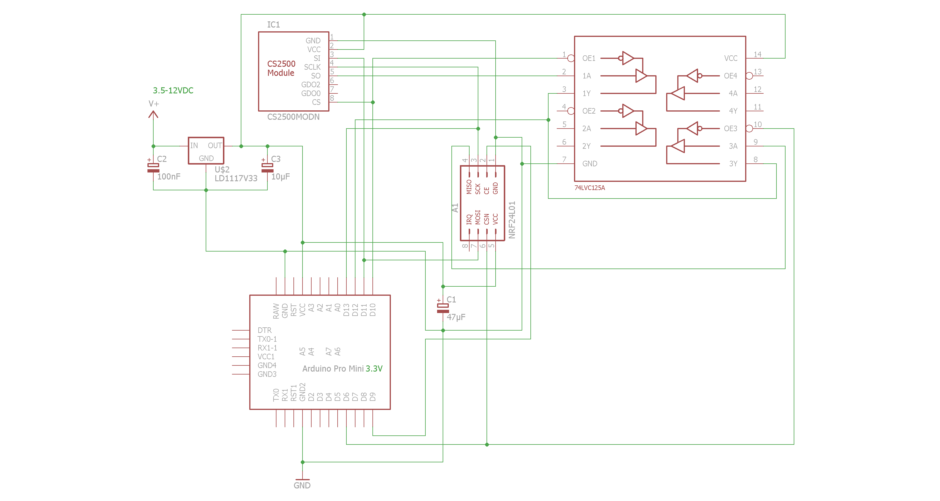
To make it easier to connect the CC2500 antenna to the Arduino I decided for a Arduino Pro Mini 3.3V. This avoids one of the 74LVC125A-circuits (which for me was a nightmare to solder !).
The schematic :
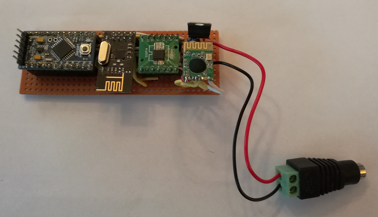
And the components mounted on a small board :
BOM:
- NRF24L01+
- Arduino Pro Mini 3.3V
- CS2500
- 74LVC125A
- 47µF capacitor
- 10 µF capacitor
- 100nF capacitor
- LD33V voltage regulator
Finally the sketch :
/*
  MTLivingColors --- Link a gen 1 Philips LivingColors lamp with MySensors.
    Author : Mathias Thorell.
-----------------------------------------------------------------------------

  This would never have been possible without the efforts of the following people :
   Ivo Knutsel   : The investigations, schematic and source code to interact with the Living Light : http://www.knutsel.org/tag/livingcolors/
   Henrik Ekblad : Founder of MySensors : www.mysensors.org
   darkoman      : Class for fading from one RGB to another RGB color : http://www.codeproject.com/Articles/13497/An-advanced-gradient-rendering-class
   johnwasser    : The Fire effect : http://forum.arduino.cc/index.php?topic=135206.msg1016852#msg1016852
   Google        : For everything else...

   2016-02-27 First working version.
   2016-02-28 Tested to adda DHT221 sensor, just for fun. Removed.
   2016-02-29 Added fading. First realese candidate.
   2016-03-01 Added Fire- and Aurora effects.
   2016-03-08 Added Water-effect (requested by my daughter Angelina).
   2016-08-05 Cleaned up and removed all non-LivingColors stuff.
   2016-08-23 Removed effects to keep theis example as clean as possible.

 Note : Make sure to undef the SOFTSPI-constant in MyConfig.h, otherwise the two radios on the SPI bus
        will not cooperate at all.

 Known issues :
        Lamp flickers while fading.

 ToDo : Fix flickering while fading.
        Add possibility to find lamp address/id. Perhaps use an I/O-pin to enter learning mode ?
        Enable handling of more than only one lamp.
        Test: Should we become a S_RGBW instead of a S_RGB lamp ?
        Shall we or shall we not handle the V_PERCENT message ?
        Store Lamp Id in program memory ?
*/
//----------------------------------------------------------------------------------
#include <MyConfig.h>
#include <MyHw.h>
#include <MyHwATMega328.h>
#include <MyMessage.h>
#include <MyParser.h>
#include <MyParserSerial.h>
#include <MySensor.h>
#include <MySigning.h>
#include <MySigningNone.h>
#include <MyTransport.h>
#include <MyTransportNRF24.h>
#include <Version.h>

#include <DigitalIO.h>
#include <DigitalPin.h>
#include <I2cConstants.h>
#include <PinIO.h>
#include <SoftI2cMaster.h>
#include <SoftSPI.h>

#include <CC2500.h>
#include <ColourConversion.h>
#include <LivingColors.h>
#include <SPI.h>
//----------------------------------------------------------------------------------
// NRF24 pins for MySensors :
#define RF24_CE_PIN       9 // Default value
#define RF24_CS_PIN       6 // Default is 10, but we must use 6 since 10 is used by the CC2500

// CC2250 pins (sharing MISO, MOSI and SCK with the NRF24)
#define lcMOSI   11    // SPI master data out pin
#define lcMISO   12    // SPI master data in pin
#define lcSCK    13    // SPI clock pin
#define lcCS     10    // SPI slave select pin 10

#define node       1 // Assigning the node Id (this will be the address for controller)
#define TheLampNum 1 // Sensor number needed in the custom devices set up

#define StateOff    0
#define StateOn     1
//----------------------------------------------------------------------------------
// Helper class :
class RGBColor
{
  private:
    int FRed,
        FGreen,
        FBlue;
  public:
    RGBColor (int Red,int Green,int Blue) :
        FRed(Red),
        FGreen(Green),
        FBlue(Blue)
    {
    }
    RGBColor(void) { FRed = 0; FGreen = 0; FBlue = 0; }
    RGBColor(const RGBColor &From) { FRed = From.Red(); FGreen = From.Green(); FBlue = From.Blue(); }

    void Set(int red,int green,int blue)  { FRed = red; FGreen = green; FBlue = blue; }
    void Set(RGBColor From) { FRed = From.Red(); FGreen = From.Green(); FBlue = From.Blue(); }
    int Red()   const { return (FRed);   }
    int Green() const { return (FGreen); }
    int Blue()  const { return (FBlue);  }
};
//----------------------------------------------------------------------------------
// Class to fade from one RGB set to another RGB set
class Fader
{
  private:
    LivingColors *FLivCol;

  public:
    // Thanks to darkoman
    /* Construct the fader for the pins to manipulate.
     * Make sure these are pins that support Pulse
     * width modulation (PWM), these are the digital pins
     * denoted with a tilde(~) common are ~3, ~5, ~6, ~9, ~10
     * and ~11 but check this on your type of arduino.
     */
    Fader(LivingColors *livCol)
    {
      FLivCol = livCol;
    }

    // Fade from in to out
    void fade(const   RGBColor &in,
              const   RGBColor &out,
              unsigned n_steps = 256,  //default take 256 steps
              unsigned timeMS  = 2)   //wait 10 ms per step
    {
      // Based on work by Darkoman; http://www.codeproject.com/Articles/13497/An-advanced-gradient-rendering-class
      double percent;
      int red,green,blue;
      for (int i = 0;i < 100;i++)
      {
        percent = 1.0 - ((double)i / (double)100);
        red   = (int)((double)in.Red()   * percent) + (int)(out.Red()   * (1.0 - percent));
        green = (int)((double)in.Green() * percent) + (int)(out.Green() * (1.0 - percent));
        blue  = (int)((double)in.Blue()  * percent) + (int)(out.Blue()  * (1.0 - percent));

        red   = red   < 0 ? 0 : red;
        green = green < 0 ? 0 : green;
        blue  = blue  < 0 ? 0 : blue;

        red   = red   > 255 ? 255 : red;
        green = green > 255 ? 255 : green;
        blue  = blue  > 255 ? 255 : blue;

        // Write the new color output :
        FLivCol->turnLampOnRGB(0,red,green,blue);

        delay(timeMS);
      }
    }
};
//----------------------------------------------------------------------------------
// NRF24
MyTransportNRF24 transport(RF24_CE_PIN,RF24_CS_PIN,RF24_PA_LEVEL_GW);

// Hardware profile
MyHwATMega328 hw;

// Main sensor class :
MySensor su;

// Main control class to handle LivingColors :
LivingColors livcol(lcCS,lcSCK,lcMOSI,lcMISO);
RGBColor CurrentRGB,LastRGB;

MyMessage livMsg(TheLampNum,V_RGB);
//----------------------------------------------------------------------------------
// Lamp address(es) :
// This is the address of my Living Colors lamp.
// To find your unique id see reference to sketch below at the call to livcol.addLamp().
unsigned char lamp1[9] = { 0x00, 0xC7, 0x87, 0x66, 0xB7, 0x1A, 0xFF, 0x8A, 0x11 }; // Lamp address

// Last known state; On (1) or Off (0)
int LastState;

// Instance of our fader class :
Fader TheFader(&livcol);
//----------------------------------------------------------------------------------
void setup()
{
  // setup serial port
  Serial.begin(115200);

  // Initialize library and add callback for incoming messages
  su.begin(DoIncomingMessage,node,true);

  // Send the sketch version information to the gateway and Controller
  su.sendSketchInfo("RGB Node","1.1");

  // Register the sensor to gw
  su.present(TheLampNum,S_RGB_LIGHT,"LivingColors");

  // Load last known states of our lamp :
  LastState = su.loadState(0); // Last lamp state
  LastRGB.Set(su.loadState(1),su.loadState(2),su.loadState(3));

  // Initialize or lamp :
  livcol.init();
  livcol.clearLamps();
  livcol.addLamp(lamp1); // Add our lamp. Lamp address/id must be taken from Ivo's original sketch from here :
                         // http://www.knutsel.org/2010/04/11/using-the-cc2500-arduino-shield/
  if (LastState)
  {
    // Turn on lamp is it was on before :
    livcol.turnLampOnRGB(0,LastRGB.Red(),LastRGB.Green(),LastRGB.Blue());
  }
  else
  {
    // Turn off lamp is it was off before :
    livcol.turnLampOff(0);
  }
}
//----------------------------------------------------------------------------------
void loop()
{
  // Do the MySensors dance :
  su.process();
}
//----------------------------------------------------------------------------------
// Parse MySensors messages :
void DoIncomingMessage(const MyMessage &message)
{
  if (message.type == V_LIGHT)
  {
     if (message.getBool())
     {
Serial.println("Lamp On");
       if (LastState == StateOff)
       {
         RGBColor fromRGB(0,0,0);
         RGBColor toRGB(LastRGB);
         TheFader.fade(fromRGB,toRGB);
       }
       livcol.turnLampOnRGB(0,LastRGB.Red(),LastRGB.Green(),LastRGB.Blue());
       LastState = su.loadState(0);
     }
     else
     {
Serial.println("Lamp Off");
       if (LastState >= StateOn)
       {
         RGBColor fromRGB(LastRGB);
         RGBColor toRGB(0,0,0);
         TheFader.fade(fromRGB,toRGB);
       }
       livcol.turnLampOff(0);

       LastState = StateOff;
     }
     // Store state in eeprom
     su.saveState(0,LastState);
  }
  else if (message.type == V_RGB)
  {
    // starting to process the hex code
    String hexstring = message.getString(); // Here goes the hex color code coming from controller through MySensors (ex: FF9A00)
    long   number = (long) strtol(&hexstring[0],NULL,16);
    CurrentRGB.Set((number >> 16) & 0xFF,(number >> 8) & 0xFF,number & 0xFF);

    // Write some debug info
Serial.print("Red is " );
Serial.println(CurrentRGB.Red());
Serial.print("Green is " );
Serial.println(CurrentRGB.Green());
Serial.print("Blue is " );
Serial.println(CurrentRGB.Blue());

    TheFader.fade(LastRGB,CurrentRGB);
    livcol.turnLampOnRGB(0,CurrentRGB.Red(),CurrentRGB.Green(),CurrentRGB.Blue());
    LastRGB.Set(CurrentRGB);
    LastState = StateOn;
    su.saveState(0,LastState);
    su.saveState(1,LastRGB.Red());
    su.saveState(2,LastRGB.Green());
    su.saveState(3,LastRGB.Blue());
  }
  else if (message.type == V_PERCENTAGE)
  {
    //Todo/missing: We need to consider this dimmer value when setting RGB's.
    String percstring = message.getString(); // 0-100 %
    long   number = (long) strtol(&percstring[0],NULL,10);
Serial.print("Dim value=");
Serial.println(number);
    double dRed   = (double)CurrentRGB.Red()   * ((double)number / 100.0);
    double dGreen = (double)CurrentRGB.Green() * ((double)number / 100.0);
    double dBlue  = (double)CurrentRGB.Blue()  * ((double)number / 100.0);

    // Nope, tested and we don't need this. Taken care of via RGB ?
    // livcol.turnLampOnRGB(0,(int)dRed,(int)dGreen,(int)dBlue);
  }
  else
  {
Serial.print("Unknown MsgType=");
Serial.println(message.type);
  }
}
//----------------------------------------------------------------------------------
(This sketch is the bare minimum to control the LivingColors lamp.
I do possess a more complete sketch which includes some nice light effects too.)
Questions and suggestions are welcome !
Enjoy !
/T