Questions for a thermostat project.
-
So this project at this point in time is not a MySensors based project, but I may make it into one in the future and use one for my home. That said,
MY PROJECT
My project is a digital thermostat using an arduino uno and a 3.2 inch touch screen TFT shield. This thermostat is going to replace the thermostat in my RV.
One difference from an RV thermostat to a normal house thermostat is that the house system typically runs on 24 volts AC whereas the RV runs on 12 volts DC. My original plan was to use the incoming 12 volts to power the uno. The specs for the UNO say that you can put up to 12 volts in the barrel jack. The only problem I have with this is that the linear regulator that the UNO has gets quite hot when running it from 12 volts. This heat will no doubt affect the temp sensor that reads the open air temp. I need to find a reasonably small way to regulate 12 volts to 5 volts without a lot of heat.MY DESIGN:
And now a bit about my design. I have most of this built and my firmware is nearly ready. I am designing it as an auto changover setup with a relay for fan speed (low or high). Here is the board setup that I have.
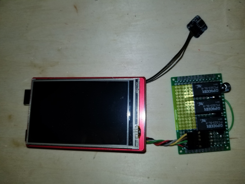
The area of the board marked in yellow will be where the screw terminals will go for connecting it to the system. The 3 relays are heat, cool and fan. I was originally going to use 5 volt relays supplied from the 5 volt pin on the arduino. I found out that when two relays would trigger, the UNO would reset. I tried adding a capacitor to the power line near the relays, but that didn't help. I am changing the relays to 12 volt relays so I can just use the incoming 12 volts to power them. I am triggering them with NPN transistors connected to 3 digital pins.Here are a few more pics of the setup. I have designed and 3D printed a case for this also.
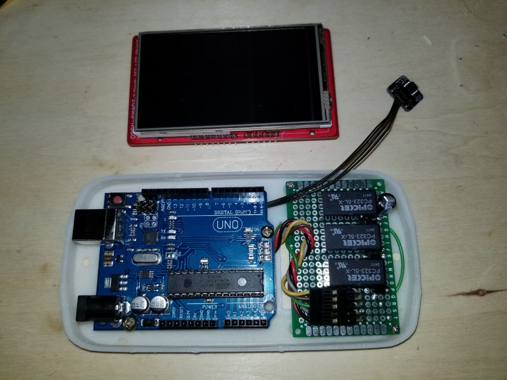
This is with the TFT shield in place.
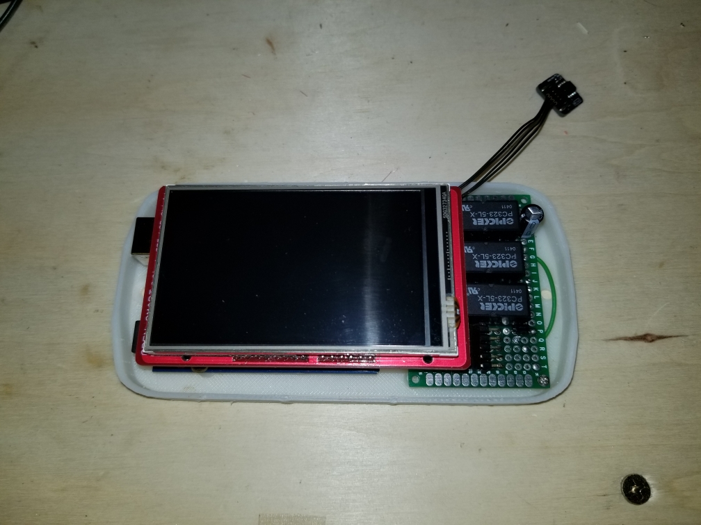
And this is with the cover in place. The cover needs a little bit of cleanup work, but otherwise not too bad.

MY FIRMWARE
And now a look at the firmware. The first image is the main screen. The main screen shows the current temp with the HVAC, fan status and set point on the right side of the screen.
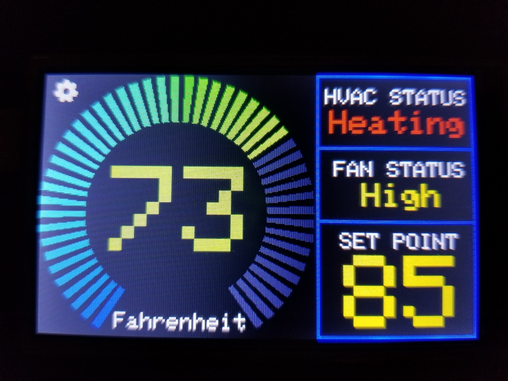
The main screen has two touch areas, the gear in the upper left corner and the set point box. Touching the gear icon gets you to the settings page, seen here.
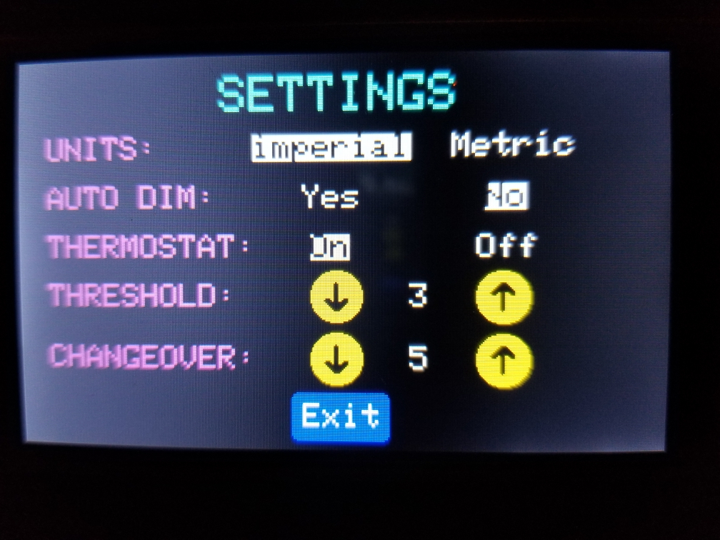
When you touch to change any setting, it is stored in the EEPROM on the UNO allowing it to recover on the same settings if it were to loose power. Most of the settings are pretty self explanatory except for the threshold and changeover settings.The threshold value is either added or subtracted from the set point to offset when the heater or AC is switched on to know if it should have the fan on high or low. if the temp is with the threshold value of the setpoint, the fan is set to low, otherwise set it to high. On the RV, this just sets the fan to low or high. On a house multi-stage HVAC system it could switch stages.
The changeover value tells the system how many degrees the temperature must go up or down from the setpoint before the system changes over from heating to cooling or vice versa.
Clicking Exit at the bottom will take you back to the main screen.
On the main screen, clicking anywhere in the box that shows the set point temp will take you to the setpoint screen.

This screen is self explanatory in its function. The up and down arrows let you set a new setpoint, and Exit at the bottom will take you back to the main screen. The setpoint value is also saved to EEPROM on any change in value. -
My main question with this was what is a small cheap and cool (literally) way of getting the 5V I need for the UNO from my 12 volt supply. Preferrably something other than a linear regulator.
@dbemowsk what you're looking for is called a dcdc buck converter.
A linear regulator burns the unused voltage. So if the input is 12 and the output is 5V, 7V is burned away, causing an efficiency of 5/12=42%. 58% will be converted to heat.
A buck converter usually has about 80-90% efficiency. 10-20% will be converted to heat.
The lm2596 could be a good choice. https://www.aliexpress.com/item/33008773592.html The datasheet says 80% efficiency at 5V output which mean 20% will be converted to heat. That's about 1/3 of the heat produced by a linear regulator.
The downside with a buck converter is that they have ripple on the output voltage. The nrf24 is very sensitive to ripple, so you might need extra capacitors to smooth out the ripple.
It is probably possible to find a buck converter that has higher efficiency and lower ripple for your use case if the lm2596 is insufficient.
-
So this project at this point in time is not a MySensors based project, but I may make it into one in the future and use one for my home. That said,
MY PROJECT
My project is a digital thermostat using an arduino uno and a 3.2 inch touch screen TFT shield. This thermostat is going to replace the thermostat in my RV.
One difference from an RV thermostat to a normal house thermostat is that the house system typically runs on 24 volts AC whereas the RV runs on 12 volts DC. My original plan was to use the incoming 12 volts to power the uno. The specs for the UNO say that you can put up to 12 volts in the barrel jack. The only problem I have with this is that the linear regulator that the UNO has gets quite hot when running it from 12 volts. This heat will no doubt affect the temp sensor that reads the open air temp. I need to find a reasonably small way to regulate 12 volts to 5 volts without a lot of heat.MY DESIGN:
And now a bit about my design. I have most of this built and my firmware is nearly ready. I am designing it as an auto changover setup with a relay for fan speed (low or high). Here is the board setup that I have.

The area of the board marked in yellow will be where the screw terminals will go for connecting it to the system. The 3 relays are heat, cool and fan. I was originally going to use 5 volt relays supplied from the 5 volt pin on the arduino. I found out that when two relays would trigger, the UNO would reset. I tried adding a capacitor to the power line near the relays, but that didn't help. I am changing the relays to 12 volt relays so I can just use the incoming 12 volts to power them. I am triggering them with NPN transistors connected to 3 digital pins.Here are a few more pics of the setup. I have designed and 3D printed a case for this also.

This is with the TFT shield in place.

And this is with the cover in place. The cover needs a little bit of cleanup work, but otherwise not too bad.

MY FIRMWARE
And now a look at the firmware. The first image is the main screen. The main screen shows the current temp with the HVAC, fan status and set point on the right side of the screen.

The main screen has two touch areas, the gear in the upper left corner and the set point box. Touching the gear icon gets you to the settings page, seen here.

When you touch to change any setting, it is stored in the EEPROM on the UNO allowing it to recover on the same settings if it were to loose power. Most of the settings are pretty self explanatory except for the threshold and changeover settings.The threshold value is either added or subtracted from the set point to offset when the heater or AC is switched on to know if it should have the fan on high or low. if the temp is with the threshold value of the setpoint, the fan is set to low, otherwise set it to high. On the RV, this just sets the fan to low or high. On a house multi-stage HVAC system it could switch stages.
The changeover value tells the system how many degrees the temperature must go up or down from the setpoint before the system changes over from heating to cooling or vice versa.
Clicking Exit at the bottom will take you back to the main screen.
On the main screen, clicking anywhere in the box that shows the set point temp will take you to the setpoint screen.

This screen is self explanatory in its function. The up and down arrows let you set a new setpoint, and Exit at the bottom will take you back to the main screen. The setpoint value is also saved to EEPROM on any change in value.@dbemowsk Great looking project!
Whilst you have gone to some length to post your project you left out a crucial bit of information - that is, how much current do you need at 5V?
Your original problem with 5V relays was probably due to not enough current available at 5V, nothing to do with the relays themselves. You might also want to investigate latching relays as that would save a lot of energy and they come in 3.3v versions as well......
Once you know the current required, search for an LDO dc switching regulator that gives about 50% more than this (just for safety and longevity of components) and then you have the answer.
As you are already soldering your own boards then adding a regulator and some caps shouldn't be too much of an issue for you.
-
My main question with this was what is a small cheap and cool (literally) way of getting the 5V I need for the UNO from my 12 volt supply. Preferrably something other than a linear regulator.
@dbemowsk Can heartily recommend the MP2315 type buck converters which were suggested to me here by @axillent as exceptionally efficient, spec says over 90% efficient and 3A, but 2A would probably be safer...
Have 2 of the USB type in my UPS (photo is somewhere here) as duty and standby, barely warm to the touch running the Pi3+Arduino gateway+HDD... -
Another buck regulator that might work:
https://lowpowerlab.com/shop/product/133Felix used it for a doorbell project and I have used for a thermostat. In those cases, we had to rectify first to get DC, but wouldn't need to since you already have DC.
-
@mfalkvidd and others. I am aware of what buck converters are and have used them before, what I was trying to avoid was changing the design of the case to make more room for something like that, but I guess if it comes down to it I may have to. I was hoping that someone might have a solution that might fit my space constraints. I like the one that @nagelc suggested as it looks like it might fit in the space I have. Another option I thought of if I had to change the size of the case was to use a couple batteries. I have some extra 18650's in my parts bin, I would need to check the current draw to determine how long they would last powering the UNO and the TFT shield.
As for the relays, I am switching them from the original 5 volt coil ones to 12 volt coils. I have decided to power them from the 12 volt supply as I should have plenty of current from that to hold a relay or two since that comes from the house batteries of the motorhome. There would never be more than two relays energized at one time since one relay is for heating and one for cooling, So it would either be a heating or cooling relay and possibly the fan relay being powered at any given time. I like the suggestion @skywatch made about using latching relays to save power, the only problem in using those is that I am limited to 3 data lines (D0 - D2) because of the TFT shield. My understanding of latching relays is that there are two types. Single coil which uses reversing the polarity for set and reset, or the dual coil type which use one coil for set and the other for reset. I think in either case I would have to use more than one data line for each relay which won't work.
-
Another buck regulator that might work:
https://lowpowerlab.com/shop/product/133Felix used it for a doorbell project and I have used for a thermostat. In those cases, we had to rectify first to get DC, but wouldn't need to since you already have DC.
