Everything nRF52840
-
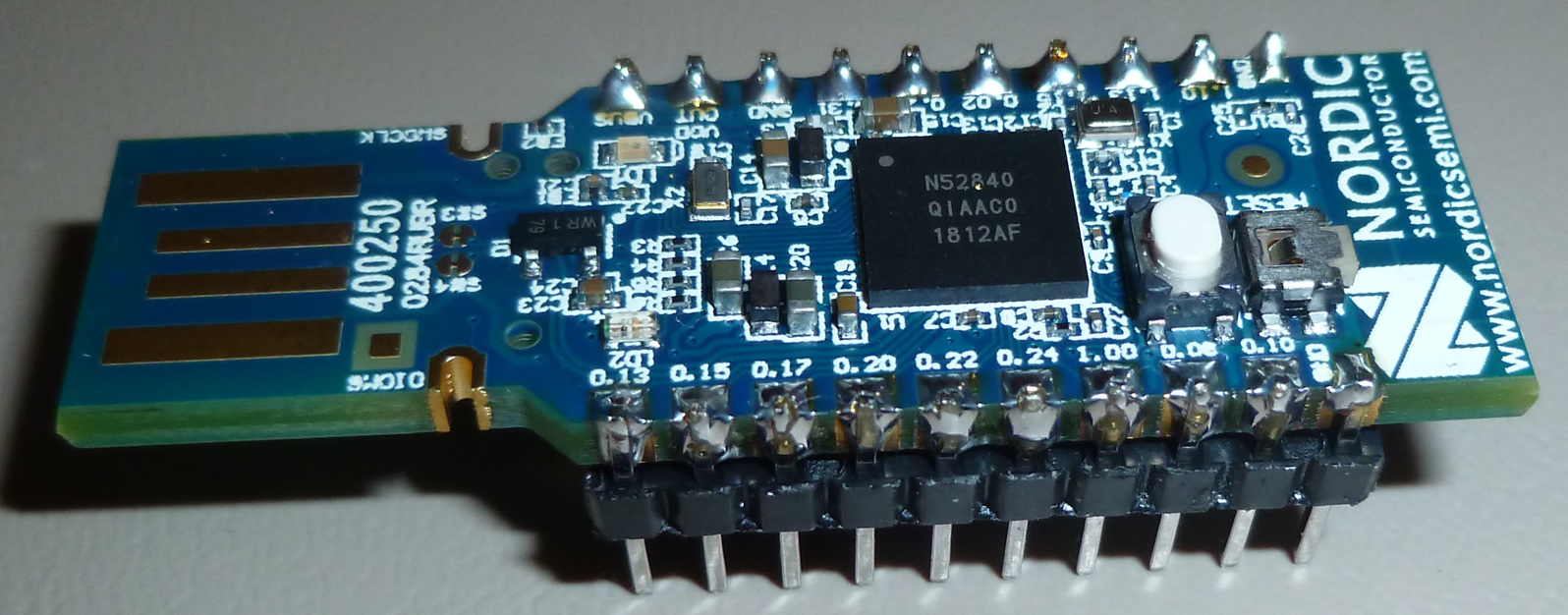
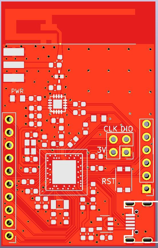
i just gave this pcb to a production, it has nrf52840 and pa/lna module, 3v3 LDO on it, practically a stand alone board with nrf52. i did not include a battery connector or charger because its for prototyping. i copied the front end part from my nrf24 modules so if i can solder it should work smoothly. tho this aQFN footprint looks very intimidating :) some of the tracks and gaps are at the manufacturers design capability tolerance limits so lets see if they gonna accept it.
@orhanyor AFAIU you're going to solder it manually, right? Will you use stencil or are you going to presoak pads? For the stencil it might be also reasonable to order a custom PCB pallet which may help to precisely align the board to the stencil. Similarly, another pallet may help to place the chip right into the center. It will be very interesting to hear from you how it went. Wish you best of luck!
I've ordered some boards with nRF52840/nRF52833, but also had to ask for assembly for exactly this reason. The PCBWay did machine soldering of the aQFN chip, and the rest were soldered manually.
By the way, the PCB price were raised two times: first, for 5 mil tolerance (the board uses NFC so I was unable to route antenna differently), and second, for ENIG finish because of the aQFN-73 package (the factory insisted on it in order to avoid soldering issues). I still have no room for the RESET, but perhaps I need to go your way and drop some unnecessary pins - that's nice idea.
-
@orhanyor Yes that aQFN footprint does look daunting. Do you have a special paste layer for the center pad that limits the paste? I've seen issues where too much paste on the ground pad will actually float the chip off the pin connections.
@Jon-Raymond exactly too much in the middle will raise it and bam you have a failed board :)
@Mishka its a wise choice to ask for assembly because of the reasons you mentioned. ENIG is kinda mentioned everywhere for this aQFN footprint otherwise surface might not be even for every single pin and it will result in failed soldering BUT i still went with HASL just to prove them wrong :))
capped via service is expensive so i just went through every single pin to examine and decide if i really need it or is it necessary for it to work and spaced them out as much as i can. i still got plenty, 3 analog pins, 9 high speed digital pins and rest is low frequency pins which are not recommended for high speed operations. it can interfere with the bluetooth signal. nordic specialist approved the design so if everything goes well it should work.
my only worry was the at the bottom side XC1 XC2 pins you can see they are really close to each other i think it was 5 mil but still it was in the capabilities so it went through. i ll see how it goes its gonna be interesting.
and yes i use stencil and a reflow oven.
how do you like the antenna performance of the nrf52840? sadly it doesnt meet my requirements so im trying this pa lna method to see if i can make it work. -
@Jon-Raymond exactly too much in the middle will raise it and bam you have a failed board :)
@Mishka its a wise choice to ask for assembly because of the reasons you mentioned. ENIG is kinda mentioned everywhere for this aQFN footprint otherwise surface might not be even for every single pin and it will result in failed soldering BUT i still went with HASL just to prove them wrong :))
capped via service is expensive so i just went through every single pin to examine and decide if i really need it or is it necessary for it to work and spaced them out as much as i can. i still got plenty, 3 analog pins, 9 high speed digital pins and rest is low frequency pins which are not recommended for high speed operations. it can interfere with the bluetooth signal. nordic specialist approved the design so if everything goes well it should work.
my only worry was the at the bottom side XC1 XC2 pins you can see they are really close to each other i think it was 5 mil but still it was in the capabilities so it went through. i ll see how it goes its gonna be interesting.
and yes i use stencil and a reflow oven.
how do you like the antenna performance of the nrf52840? sadly it doesnt meet my requirements so im trying this pa lna method to see if i can make it work.@orhanyor said in Everything nRF52840:
BUT i still went with HASL just to prove them wrong :))
I'll be not too wrong if say that literally everybody out there is waiting for the result :-)
capped via service is expensive so i just went through every single pin to examine and decide if i really need it or is it necessary for it to work and spaced them out as much as i can...
nordic specialist approved the design so if everything goes well it should work.Yeah, HDI is too expensive for small batches. I'm just wondering how Adafruit managed to make those boards at that price. As to me the only reasonable explanation is that they produce thousands of them.
my only worry was the at the bottom side XC1 XC2 pins you can see they are really close to each other i think it was 5 mil but still it was in the capabilities so it went through. i ll see how it goes its gonna be interesting.
You might want drop the P0.26 GPIO I think.
how do you like the antenna performance of the nrf52840? sadly it doesnt meet my requirements so im trying this pa lna method to see if i can make it work.
IMHO the SoC itself is fantastic. Unfortunately, so far the only boards I have on hands are a couple of those E73 by CDEBYTE - just received them few days ago, but still had no time for them. Also, a number of nrf52833 based Raybeacons are stuck in fabrication. They're not about long range though - the board has low-performance zero clearance antenna.
The built-in 8dBm TX amplifier is a great add-on. It comes at cost of higher current consumption, of course, so it's subject of proper battery selection for the application. An external 20dBm amplifier may require up to 150mA which will drain battery like a hog. IMHO for the cases when you need it really long a directional antenna is must.
On the other hand, if you have to have good coverage in the center of a building it might be reasonable to stick with an amplifier. But while you're waiting for the boards, I'd suggest to give a second try to your IPEX modules with this simple DIY biquad antenna: https://martybugs.net/wireless/biquad/. It's very easy to build and promises to add more than 10dBi to your link budget. I remember I used it to feed a pair of 1m dishes (i.e. about +25dBi more) for long range wifi - worked like a charm.
Another interesting option might be a phased array antenna. The active array will add up about 10-15dBi which is perfectly aligned to peer direction. Not sure will it be any affordable though. A passive array might be much easier to implement in PCB, but you have to align it manually.
-
@orhanyor said in Everything nRF52840:
BUT i still went with HASL just to prove them wrong :))
I'll be not too wrong if say that literally everybody out there is waiting for the result :-)
capped via service is expensive so i just went through every single pin to examine and decide if i really need it or is it necessary for it to work and spaced them out as much as i can...
nordic specialist approved the design so if everything goes well it should work.Yeah, HDI is too expensive for small batches. I'm just wondering how Adafruit managed to make those boards at that price. As to me the only reasonable explanation is that they produce thousands of them.
my only worry was the at the bottom side XC1 XC2 pins you can see they are really close to each other i think it was 5 mil but still it was in the capabilities so it went through. i ll see how it goes its gonna be interesting.
You might want drop the P0.26 GPIO I think.
how do you like the antenna performance of the nrf52840? sadly it doesnt meet my requirements so im trying this pa lna method to see if i can make it work.
IMHO the SoC itself is fantastic. Unfortunately, so far the only boards I have on hands are a couple of those E73 by CDEBYTE - just received them few days ago, but still had no time for them. Also, a number of nrf52833 based Raybeacons are stuck in fabrication. They're not about long range though - the board has low-performance zero clearance antenna.
The built-in 8dBm TX amplifier is a great add-on. It comes at cost of higher current consumption, of course, so it's subject of proper battery selection for the application. An external 20dBm amplifier may require up to 150mA which will drain battery like a hog. IMHO for the cases when you need it really long a directional antenna is must.
On the other hand, if you have to have good coverage in the center of a building it might be reasonable to stick with an amplifier. But while you're waiting for the boards, I'd suggest to give a second try to your IPEX modules with this simple DIY biquad antenna: https://martybugs.net/wireless/biquad/. It's very easy to build and promises to add more than 10dBi to your link budget. I remember I used it to feed a pair of 1m dishes (i.e. about +25dBi more) for long range wifi - worked like a charm.
Another interesting option might be a phased array antenna. The active array will add up about 10-15dBi which is perfectly aligned to peer direction. Not sure will it be any affordable though. A passive array might be much easier to implement in PCB, but you have to align it manually.
@Mishka i was looking at that long range support of nrf52840 by lowering the data rate to 500kbps or 125 kbps you gain a significant amount of range like 4 fold but it requires a coded PHY which is not available in arduino environment at least not that i know of. adafruit marked it in their to do list but know knows when they gonna implement it probably thats why nrf24's make a significant difference in signal strength when you lower the data rate to 250kbps.
Yes that amplifier draws quite abit of current i think it was up to 350ma when tx is on but ofc it is not on all the time so but still its not for everyone.
i will look into that antenna you mentioned while im waiting for the pcbs thank you for the suggestion!
antenna that i used in the pcb is this one: i read its better than chip antennas but ofc at a much bigger footprint
http://www.ti.com/lit/an/swru120d/swru120d.pdf -
@orhanyor I can confirm this pcb antenna works well. I used it with 52832 a while ago. You'll certainly need to tune it to get the exact target freq though, usually to do on each new pcb design&shape (so it's not shifted too much compared to your others nodes), but it's a good antenna, easy to use, resistant to detuning. This is the recommended ant by TI for 2.4ghz.
Here I just have one bt840xe on custom gw (dual band gw, using BLE for 2.4ghz) with good external ant, it has very good range. I didn't design the 52840+PA because I preferred to have ce/fcc for PA, and for one device only, it wasn't worth the shot. For others nodes, I don't need PA, or prefer mysensors subghz for very long range.
For a devboard, this looks nice, but depending on the target application and sensitive sensors etc, maybe adding an rf shield could help in some cases, especially as you're planning to use a power amplifier. Spectrum analyzer (or a vna) can help to check this (bad rf emissions too, passive filtering can help) and optimize range.good luck for your soldering :)
-
@orhanyor I can confirm this pcb antenna works well. I used it with 52832 a while ago. You'll certainly need to tune it to get the exact target freq though, usually to do on each new pcb design&shape (so it's not shifted too much compared to your others nodes), but it's a good antenna, easy to use, resistant to detuning. This is the recommended ant by TI for 2.4ghz.
Here I just have one bt840xe on custom gw (dual band gw, using BLE for 2.4ghz) with good external ant, it has very good range. I didn't design the 52840+PA because I preferred to have ce/fcc for PA, and for one device only, it wasn't worth the shot. For others nodes, I don't need PA, or prefer mysensors subghz for very long range.
For a devboard, this looks nice, but depending on the target application and sensitive sensors etc, maybe adding an rf shield could help in some cases, especially as you're planning to use a power amplifier. Spectrum analyzer (or a vna) can help to check this (bad rf emissions too, passive filtering can help) and optimize range.good luck for your soldering :)
@scalz thanks for the input, ive seen they tune it by cutting a length from the longer end but in order to do that i need equipment which i dont have so its going to be a hit or miss :) if it doesnt work well i can use SMA antenna but i think thats the least of my worries with that pcb. I like to experiment and see for myself so even if its wasted its ok :)
-
So, 8dBm built-in, plus 20dBm PA, plus 12dBi for the feedhorn, plus 20dBi for the dish. Add the coded PHY on top of this. Does anybody want to set a record? =)
In a meanwhile, here is
the nRF52840 range test with Johanson 2450AT18D0100 chip-antenna and SAFFB2G45MA0F0A 1dB attenuator
the nRF9160 range test: https://www.youtube.com/watch?v=p1_0OAlTcuY (spoiler - 14 km). -
In a meanwhile, here is
the nRF52840 range test with Johanson 2450AT18D0100 chip-antenna and SAFFB2G45MA0F0A 1dB attenuator
the nRF9160 range test: https://www.youtube.com/watch?v=p1_0OAlTcuY (spoiler - 14 km).@Mishka said in Everything nRF52840:
In a meanwhile, here is the nRF52840 range test with Johanson 2450AT18D0100 chip-antenna and SAFFB2G45MA0F0A 1dB attenuator: https://www.youtube.com/watch?v=p1_0OAlTcuY (spoiler - 14 km).
typo?? from the video, it seems to be nRF9160
-
@Mishka said in Everything nRF52840:
In a meanwhile, here is the nRF52840 range test with Johanson 2450AT18D0100 chip-antenna and SAFFB2G45MA0F0A 1dB attenuator: https://www.youtube.com/watch?v=p1_0OAlTcuY (spoiler - 14 km).
typo?? from the video, it seems to be nRF9160
-
@Mishka I meant nrf52840 does not do LTE/NB-IOT. 52840 is used as controller/bridge to bluetooth (14km range isn't for bluetooth). but yes their NB-IOT sip looks nice
-
Adafruit now has an alpha release nRF52840 offering in a BBC microbit form factor:
https://www.adafruit.com/clue
The listing says it's programmable from the Arduino IDE.
The original micro:bit seems locked in time, with no official mcu upgrades from micro:bit itself, but nonetheless by the end of 2018 over two million micro:bits had been distributed globally. Pretty amazing for such a minimalist, barebones platform.
-
Adafruit now has an alpha release nRF52840 offering in a BBC microbit form factor:
https://www.adafruit.com/clueThe listing says it's programmable from the Arduino IDE.
The original micro:bit seems locked in time, with no official mcu upgrades from micro:bit itself, but nonetheless by the end of 2018 over two million micro:bits had been distributed globally. Pretty amazing for such a minimalist, barebones platform.
@NeverDie Ya Adafruit's Clue looks great. I just wish they would have added one more button to the front so up/down/select could be used for a menu system on the display.
-
@NeverDie Ya Adafruit's Clue looks great. I just wish they would have added one more button to the front so up/down/select could be used for a menu system on the display.
@Jon-Raymond said in Everything nRF52840:
@NeverDie Ya Adafruit's Clue looks great. I just wish they would have added one more button to the front so up/down/select could be used for a menu system on the display.
Maybe you could program one of pads #0, #1, or #2 to be a capacitive touch equivalent of the extra button you wish it had?
-
@Jon-Raymond said in Everything nRF52840:
@NeverDie Ya Adafruit's Clue looks great. I just wish they would have added one more button to the front so up/down/select could be used for a menu system on the display.
Maybe you could program one of pads #0, #1, or #2 to be a capacitive touch equivalent of the extra button you wish it had?
@NeverDie Yes that is a good option or use the accelerometer to sense an input.
-
A datasheet for the new nRF5340 is now available: https://infocenter.nordicsemi.com/pdf/nRF5340_OPS_v0.5.1.pdf
It has some improvements, but some of its competition seems to be much lower power.
-
Reading all of this, I think I made a mistake buying the e73-2G4M08S1C and a Deb board. I doubt I have the capabilities to solder this board properly. Since I have no experience designing boards, is there any simple breakout board design available I can order from pcbway so I can at least solder the outer pins?
The only board I found was this one:
https://www.openhardware.io/view/745/Light-and-shock-sensor-or-nRF52840-or-MySensors-or-ZigBee
Hello! It looks like you're interested in this conversation, but you don't have an account yet.
Getting fed up of having to scroll through the same posts each visit? When you register for an account, you'll always come back to exactly where you were before, and choose to be notified of new replies (either via email, or push notification). You'll also be able to save bookmarks and upvote posts to show your appreciation to other community members.
With your input, this post could be even better 💗
Register Login