Windows GUI/Controller for MySensors
-
@tekka cool software! btw the sorting of the child sensors in the tree could be optimized.
Right now the nodes are sorted like string instead of numbers:0 - ...
1 - ...
10 -
11 -
...
2 -
21-
... -
Greetings Tekka,
I am teaching myself programming while learning about the NRF24L01+ and various controllers and sensors. I have tried to download several free software controllers but yours is the only one that was straightforward enough for me to be successful. I have used it to monitor communication to and from my gateway but I am at a loss as to how to use your creation as a controller. It is the most wonderful tool for visualizing and debugging node-to-gateway communications because of the exceptional work you have done translating the command codes into real command words.
Is there a way to input data through your GUI or is it best used as an output device? If input is accepted, would you be so kind as to elaborate on the subject enough to get me moving?
Respectfully - Baran
-
I'm looking some days into this topic, although I found not the time to test your very good looking software - The issue mentioned by dzairo would also be important for me. As I run my nodes at 8MHz I cannot use the default 115200kbps and use (also) 38kbps - so it would be important for me to change the BAUD rate too.
Anyways - nice work!
-
Thank you for this excellent work. I look forward to using it in my network. I just have a couple questions regarding setting up the GUI. I've read through this thread several times, but still have a couple of gaps in my understanding.
-
Is the gateway that interfaces with the GUI an additional gateway which listens to, and sends node messages and updates? That is, additional to one that is interfaced with the controller (in my case a serial gateway connected to a Vera controller)?
-
If my the answer to my first question is, yes, it is an additional gateway, is the code defining the operation different such that is does not interfere with the 'true' gateway? Or is the code the same (standard serial gateway sketch) but simply does not interfere?
-
Do the nodes require the MYSBootloader in order to show up in the 'messages' tab, or will 'messages' tab show all node traffic regardless of bootloader? Of course for over the air (OTA) sketch updates it needs the MYSBootloader.
-
Are these the correct steps to setup operation:
a) download and extract the files.
'b) place the bootloader folder into /arduino/hardware path such that the MYSBootloader and the associated boards show up in the 'tools->boards' menu.
c) connect an Arduino with the gateway sketch to a computer using a USB cable (for the serial connection).
d) run MYSController.exe (on windows) and select the COM port of the serial gateway in the configuration.
e) hit connect and node traffic will show up in the 'messages' tab.
If this is correct (and now that I write it down) it seems pretty straightforward, but I didn't see it explicitly described elsewhere. Sorry to be such a beginner, and thanks for straightening me out if I'm incorrect in any step.
-
-
Thank you for this excellent work. I look forward to using it in my network. I just have a couple questions regarding setting up the GUI. I've read through this thread several times, but still have a couple of gaps in my understanding.
-
Is the gateway that interfaces with the GUI an additional gateway which listens to, and sends node messages and updates? That is, additional to one that is interfaced with the controller (in my case a serial gateway connected to a Vera controller)?
-
If my the answer to my first question is, yes, it is an additional gateway, is the code defining the operation different such that is does not interfere with the 'true' gateway? Or is the code the same (standard serial gateway sketch) but simply does not interfere?
-
Do the nodes require the MYSBootloader in order to show up in the 'messages' tab, or will 'messages' tab show all node traffic regardless of bootloader? Of course for over the air (OTA) sketch updates it needs the MYSBootloader.
-
Are these the correct steps to setup operation:
a) download and extract the files.
'b) place the bootloader folder into /arduino/hardware path such that the MYSBootloader and the associated boards show up in the 'tools->boards' menu.
c) connect an Arduino with the gateway sketch to a computer using a USB cable (for the serial connection).
d) run MYSController.exe (on windows) and select the COM port of the serial gateway in the configuration.
e) hit connect and node traffic will show up in the 'messages' tab.
If this is correct (and now that I write it down) it seems pretty straightforward, but I didn't see it explicitly described elsewhere. Sorry to be such a beginner, and thanks for straightening me out if I'm incorrect in any step.
@therik said:
Is the gateway that interfaces with the GUI an additional gateway which listens to, and sends node messages and updates? That is, additional to one that is interfaced with the controller (in my case a serial gateway connected to a Vera controller)?
No, but certainly a good idea to look into.
Do the nodes require the MYSBootloader in order to show up in the 'messages' tab, or will 'messages' tab show all node traffic regardless of bootloader? Of course for over the air (OTA) sketch updates it needs the MYSBootloader.
No, the MYSBootloader is required for OTA updates with MYSController or compatible controllers.
Are these the correct steps to setup operation:
a) download and extract the files.
'b) place the bootloader folder into /arduino/hardware path such that the MYSBootloader and the associated boards show up in the 'tools->boards' menu.
c) connect an Arduino with the gateway sketch to a computer using a USB cable (for the serial connection).
d) run MYSController.exe (on windows) and select the COM port of the serial gateway in the configuration.
e) hit connect and node traffic will show up in the 'messages' tab.
Yes, that's pretty much it. Copying the bootloader directory is only needed for updating to MYSBootloader via ISP.
-
-
@tekka Hello, I check your great software and do my first steps with mySensors.
It looks very amazing!
Here are my first comments:
- I must program the MYSBootloader with the H-fuse setting H:0xD8 (2048 word), the value H:0xDE (in your fuses.txt) or H:0xDA (in your boards.txt) didn't work for me.
- The blink.hex seems to be the normal blink sketch, it didn't have nrf24 functionality. Needs a local hardreset to flash other firmware.
- The Arduino IDE (with the enhanced boards.txt) isn't able to program a firmware with the MYSBootloader - think this results in the higher baud rate (115200 vs. 57600) and my case to have the Arduino running in a VM !?
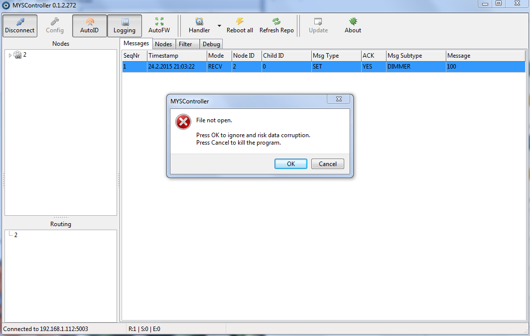
- The update function in MYSController isn't working because it needs a proxy configuration (not imported).
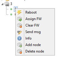
- I got a warning sign on the nodes-tree, don't know what it mean, but node is working (no info in the context menu).
- The interrupt line of the ner24L01 isn't needed.
- A right click in the open context menu ( e.g. on clear firmware) forces a software error.
8 ) After connecting the Serial GW the MYSController doesn't responce for a while (searching for nodes?) Maybe a background task or an indicater would be a idea ?!
9)On XP (or XP style) a selected row in the mesages or nodes tab is not readable - the selection is in dark blue, the text in black.
It should be possible to use the MYSBootloder (.hex) without changes also for 8Mhz nodes (internal RC L:0xE2), OTA only.
The SPI is independent from the clock, Uart is not used, delays are 2 times longer but this should be no problem.Is there a scenario to keep your MYSController connected and have the mash working at the same time?
For example, with a gateway connected at Raspberry PI and a TCP connection from MYSController to the RPI? Or with two gateways ?Looking forward for the next features :-),
regards Pit -
@tekka Hello, I check your great software and do my first steps with mySensors.
It looks very amazing!
Here are my first comments:
- I must program the MYSBootloader with the H-fuse setting H:0xD8 (2048 word), the value H:0xDE (in your fuses.txt) or H:0xDA (in your boards.txt) didn't work for me.
- The blink.hex seems to be the normal blink sketch, it didn't have nrf24 functionality. Needs a local hardreset to flash other firmware.
- The Arduino IDE (with the enhanced boards.txt) isn't able to program a firmware with the MYSBootloader - think this results in the higher baud rate (115200 vs. 57600) and my case to have the Arduino running in a VM !?
- The update function in MYSController isn't working because it needs a proxy configuration (not imported).
- I got a warning sign on the nodes-tree, don't know what it mean, but node is working (no info in the context menu).
- The interrupt line of the ner24L01 isn't needed.
- A right click in the open context menu ( e.g. on clear firmware) forces a software error.
8 ) After connecting the Serial GW the MYSController doesn't responce for a while (searching for nodes?) Maybe a background task or an indicater would be a idea ?!
9)On XP (or XP style) a selected row in the mesages or nodes tab is not readable - the selection is in dark blue, the text in black.
It should be possible to use the MYSBootloder (.hex) without changes also for 8Mhz nodes (internal RC L:0xE2), OTA only.
The SPI is independent from the clock, Uart is not used, delays are 2 times longer but this should be no problem.Is there a scenario to keep your MYSController connected and have the mash working at the same time?
For example, with a gateway connected at Raspberry PI and a TCP connection from MYSController to the RPI? Or with two gateways ?Looking forward for the next features :-),
regards Pit@pit007 Thanks for your feedback.
- I must program the MYSBootloader with the H-fuse setting H:0xD8 (2048 word), the value H:0xDE (in your fuses.txt) or H:0xDA (in your boards.txt) didn't work for me.
Ups, this is a mistake in the fuses.txt file, I will update that. The settings in the boards.txt are correct.
The MYSBootloader 1.0 is 1834 bytes in size, therefore 0xDA works (1024W), but 0xD8 (2048W) is also ok (assuming you are programming the atmega328p). All calls are relative, and the MCU skips invalid commands (0xFF) until it starts parsing at 0x7800.- The blink.hex seems to be the normal blink sketch, it didn't have nrf24 functionality. Needs a local hardreset to flash other firmware.
yep, correct :)
- The Arduino IDE (with the enhanced boards.txt) isn't able to program a firmware with the MYSBootloader - think this results in the higher baud rate (115200 vs. 57600) and my case to have the Arduino running in a VM !?
With MYSBootloader 1.0 you can only program a firmware with MYSController or similar tools. I'm currently working on a dual bootloader that includes OTA and Arduino IDE/AVRDude programming.
- The update function in MYSController isn't working because it needs a proxy configuration (not imported).
Hmm, I assume you are referring to the check for updates function (automatically triggered after startup)? I will look into that.
- I got a warning sign on the nodes-tree, don't know what it mean, but node is working (no info in the context menu).
The warning sign means no version/type information received. This information is sent during MYSBootloader startup, but not with conventional (e.g. optiboot) bootloaders.
- The interrupt line of the ner24L01 isn't needed.
The communication is entirely controlled by the gateway - and yes, the interrupt pin is not used in the current gateway setup.
- A right click in the open context menu ( e.g. on clear firmware) forces a software error.
Please send a screenshot to myscontroller@gmail.com
8 ) After connecting the Serial GW the MYSController doesn't responce for a while (searching for nodes?) Maybe a background task or an indicater would be a idea ?!
Please check the debug tab: any truncated messages or error flags after startup?
- On XP (or XP style) a selected row in the messages or nodes tab is not readable - the selection is in dark blue, the text in black.
ok, will look into that.
It should be possible to use the MYSBootloder (.hex) without changes also for 8Mhz nodes (internal RC L:0xE2), OTA only.
The SPI is independent from the clock, Uart is not used, delays are 2 times longer but this should be no problem.Yes, 8Mhz should work, but ideally you recompile the bootloader with F_CPU set to 8 Mhz for correct delay timings.
Is there a scenario to keep your MYSController connected and have the mash working at the same time?
For example, with a gateway connected at Raspberry PI and a TCP connection from MYSController to the RPI? Or with two gateways ?Not yet, but I have some ideas...
Have fun
-
Hi and thanks for a cool piece of software!
I finally got around to soldering an ethernet gateway and decided to give this a spin. It worked like a charm for a while but now I get this error everytime any message goes through the gateway to Vera:
OS is 32-bit Windows 7
I can only get rid of this behaviour if I delete the configuration settings file and start over. It seems it only happens if I have logging enabled and exit the program and restart it.
I'll have to start playing with the bootloader soon to get the OTA capabilities.
-
Hi.
Just one idea .. your tools is very good .. why not add more better function ..
1.If not received data from sensor more than predefined time then send email or tweet .. etc. for example using https://www.pushingbox.com/
2. Make server version .. for web interface ..
I thinks .. is possible order in TESCO cheap windows 8.1 tablet in price 90Euros ..
one or two year later then will be possible buy in price around 50 euros .. why not use this platform?
I use ASUS with USB serial port and work good .. if make easy uart to wifi (esp8266) converter then can work directly with wifi.. -
yes.. I just that user use RPi etc hardware solution .. but in fact
is possible buy tablet .. complete solution : standard windows 8.1 , LCD , battery .. wifi , bluetooth .. CE .. why not use this platform ..
give link for - home automation solution..regards..
PS: you can see , I my self make similar software for windows ..but more easy .. and why not use windows core for server , database .. etc ..
-
@tekka This GUI is great help especially for beginners like me who don't understand what the serial messages mean! You extract all the information so well and so beautifully.
Hope its not too much to ask, but may I take a look at the source code? Because I need to know the method you used to extract the messages, as well as tying the data to the proper fields. I somehow need to push all of these data to the proper fields in my database and I'm stuck at deciphering the messages being received. Thanks in advance and cheers! -
This is a nice tool. Good work! Is there any possibility to get support for all the message types on the development branch as well?
Hello! It looks like you're interested in this conversation, but you don't have an account yet.
Getting fed up of having to scroll through the same posts each visit? When you register for an account, you'll always come back to exactly where you were before, and choose to be notified of new replies (either via email, or push notification). You'll also be able to save bookmarks and upvote posts to show your appreciation to other community members.
With your input, this post could be even better 💗
Register Login