💬 Minimal LiPo powered Arduino Pro Mini + RFM95 MySensors node
-
-
@Joost I have a question about the current consumption of your setup.
"This board is in use now; I get the anticipated 6-9µA sleep current, together with a BME280 sensor approx. 12µA."
So if I understand correctly you are getting 6-9µA with- a Pro Mini 3.3V/8MHz with removed regulator and power led
- a RFM95/6 transceiver module
- a low quiescent PMIC (MCP1700-33 SOT-23)
- a voltage divider for battery voltage measurement via Arduino Pin A0 (two 1206 SMD resistors; 1M and 470K)
How did you get such low power consumption?:open_mouth:
The original MySensors site article https://www.mysensors.org/build/battery speaks about a 120µA for a pro mini without regulator and powerled, a DS18B20 temp sensor and radio nRF24L01+.
I'm getting with only my Pro Mini and using the LowPower sketch, a 133µA in deep sleep
(https://forum.mysensors.org/topic/4796/battery-powered-sensors/243)
@Yveaux responded that 133µA was pretty close to the mentioned 120µA (https://forum.mysensors.org/topic/4796/battery-powered-sensors/247), so I did not search further.
But now I'm stumbling on your topic :confused:In your topic you are saying nothing about running the Pro Mini with a BOD disable and on the internal 1MHz clock to also reduce power consumption.
Are your Pro Mini's running on the standard external 8MHz clock and no BOD disable?I have tested several of my Chinese Pro Mini's to see their power consumption and all are about 133µA in deep sleep.
So could the quality of the Pro Mini play a role here?
Where did you get your Pro Mini's 3.3V 8MHz? -
@Joost A second question.
I love your Pro Mini breakout shield.
EDIT: not correct :-(
I'm using the RFM69HW transmitter but if my information are correct the RFM95 and RFM69HW are pin compatible.
But the RFM95 and the RFM69HCW are pin compatible! :-)
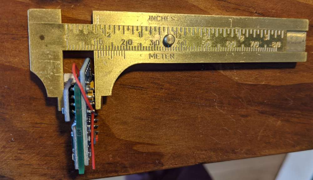
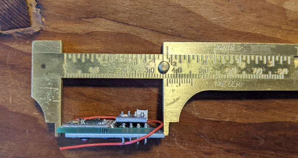
Could you give information about the dimensions? Especially about the thickness. -
HI, I'll try to get back to you this weekend and re-measure my power consumption (you're correct, these are unmodified 8MHz/3.3V Pro Minis, no modified bootloader or anything). The consumption was measured with two relatively cheap multimeters, giving the same result (in comparison to your link without the DS18B20 and with a RFM95), though I'm pretty confident this would be kind of correct.
Btw. you mean the thickness of the radio module on its own?
-
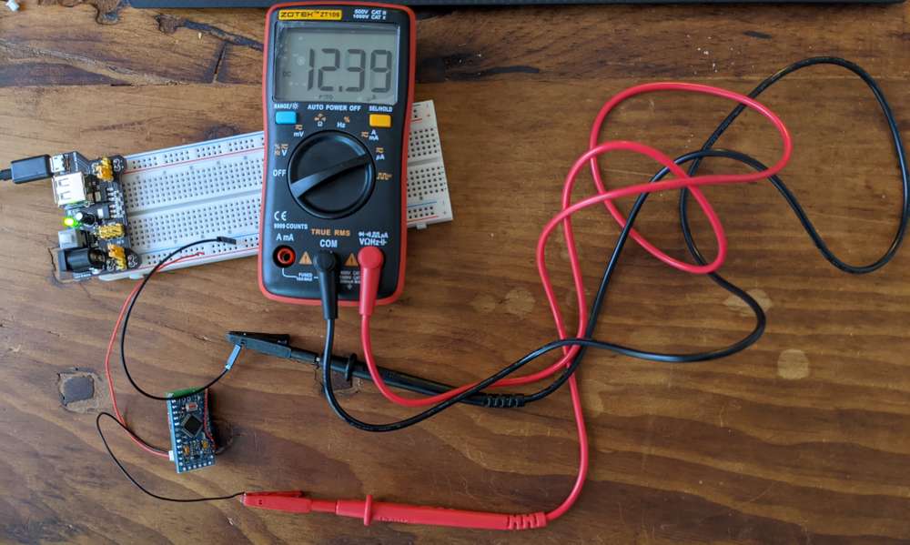
Hi, with a newer, potentially better DMM I found 12.4µA at 3.3V for a Pro Mini (3.3/8MHz, regulator and power LED removed, stock bootloader) with a BME280 (which has an additional, in this 3.3V setting unneeded, power regulator on board that could be removed) and a RFM95/96, at deep sleep.
Also I got you some pic of the dimensions for that older version of the board I had lying around.
Cheers, Joost


-
Maybe we are comparing deep sleep current vs. a "mix" of deep sleep and wake times added together and averaged? See differences between those approaches in the first
vs. these last two links:
-
Thanks for the dimensions :-)
That will work in my setup!I have read also these links with results much better then my 133µA.
I have tested my pro mini with the lowpower sketch to get the pro mini in deep sleep and I measure 133µA. My multimeter is already 30 years old and his last calibration was 20 years ago? But the voltage measurements are still correct, so I don't know...
LowpowerLab has a Current Sense Amplifier device, but for 141 euros it is bit expensive ;-)You didn't mention where you did buy your Pro Mini's? I'm thinking about the quality of the used electronics...
@evb 133uA is a lot. Why do you use the lowpower sketch? There are lots of ways to reduce consumption in deep sleep, and the Mysensors library sleep function does a pretty good job of it. For best results you should use a bootloader with fuse settings for 8mhz internal resonator and no BOD. 1mhz is even lower, but not so much to gain from it.
-
@evb 133uA is a lot. Why do you use the lowpower sketch? There are lots of ways to reduce consumption in deep sleep, and the Mysensors library sleep function does a pretty good job of it. For best results you should use a bootloader with fuse settings for 8mhz internal resonator and no BOD. 1mhz is even lower, but not so much to gain from it.
Hi @olka, on the topic https://forum.mysensors.org/topic/4796/battery-powered-sensors/243 you can read the whole story :-)
The lowpower sketch is just used for measurement of the deepsleep power consumption to have an equivalent software sketch when comparing the results with the results from the given links like See table "The Simple @ 8Mhz"
It was done with only the Pro Mini with no regulator and no power led.The only difference I see now is the build quality of the Pro Mini itself.
Do you use also Pro Mini with these low currents in deepsleep?
If yes, from where did you get them? -
Hi @olka, on the topic https://forum.mysensors.org/topic/4796/battery-powered-sensors/243 you can read the whole story :-)
The lowpower sketch is just used for measurement of the deepsleep power consumption to have an equivalent software sketch when comparing the results with the results from the given links like See table "The Simple @ 8Mhz"
It was done with only the Pro Mini with no regulator and no power led.The only difference I see now is the build quality of the Pro Mini itself.
Do you use also Pro Mini with these low currents in deepsleep?
If yes, from where did you get them?@evb, I really don't know why you get that high consumption of 133uA, but there is defenently someting wrong. Sorry that I cant help.
I use my own pcb design but it's basically the same as a mini pro without reg and led + RFM69HW. All my 328 chips is sourced from china and working fine.
I just measured on of my older designs with 8mhz/no BOD and I get about 6.7uA in timed sleep (WDT active), including 1M/470k voltage divider.
With the same setup without 1M/470k voltage divider and with external interrupt wake-up (sleep forever) I have about 0.8uA.This was measured with two different multimeters with uA range. Sure, in this range a multimeter is not as accurate as the uCurrent or similar instruments, but IMO more than good enough for this kind of measurement.
If you are able to solve your main problem, I have a few other tips for further tweeking:
- Don't use bootloader with BOD, you don't need it for a sensor that is continous connected to the battery. Saves 20-25uA.
- If you power from 3V battery, don't use the suggested 1M/470k voltage divider for battery monitoring, you can do battery monitoring with code only (search here on the forum for it). Saves 2uA.
- You could perhaps gain a tiny bit more by setting all unused pins to LOW OUTPUT or LOW INPUT.
Some very good info on ATmega 328 power consumption here: https://www.gammon.com.au/forum/?id=11497
-
@evb, I really don't know why you get that high consumption of 133uA, but there is defenently someting wrong. Sorry that I cant help.
I use my own pcb design but it's basically the same as a mini pro without reg and led + RFM69HW. All my 328 chips is sourced from china and working fine.
I just measured on of my older designs with 8mhz/no BOD and I get about 6.7uA in timed sleep (WDT active), including 1M/470k voltage divider.
With the same setup without 1M/470k voltage divider and with external interrupt wake-up (sleep forever) I have about 0.8uA.This was measured with two different multimeters with uA range. Sure, in this range a multimeter is not as accurate as the uCurrent or similar instruments, but IMO more than good enough for this kind of measurement.
If you are able to solve your main problem, I have a few other tips for further tweeking:
- Don't use bootloader with BOD, you don't need it for a sensor that is continous connected to the battery. Saves 20-25uA.
- If you power from 3V battery, don't use the suggested 1M/470k voltage divider for battery monitoring, you can do battery monitoring with code only (search here on the forum for it). Saves 2uA.
- You could perhaps gain a tiny bit more by setting all unused pins to LOW OUTPUT or LOW INPUT.
Some very good info on ATmega 328 power consumption here: https://www.gammon.com.au/forum/?id=11497
@olka said in 💬 Minimal LiPo powered Arduino Pro Mini + RFM95 MySensors node:
you can do battery monitoring with code only (search here on the forum for it)
@evb I wrote a small library for it: https://github.com/Yveaux/Arduino_Vcc
-
Thanks for the dimensions :-)
That will work in my setup!I have read also these links with results much better then my 133µA.
I have tested my pro mini with the lowpower sketch to get the pro mini in deep sleep and I measure 133µA. My multimeter is already 30 years old and his last calibration was 20 years ago? But the voltage measurements are still correct, so I don't know...
LowpowerLab has a Current Sense Amplifier device, but for 141 euros it is bit expensive ;-)You didn't mention where you did buy your Pro Mini's? I'm thinking about the quality of the used electronics...
@evb said in 💬 Minimal LiPo powered Arduino Pro Mini + RFM95 MySensors node:
Thanks for the dimensions :-)
That will work in my setup!I have read also these links with results much better then my 133µA.
I have tested my pro mini with the lowpower sketch to get the pro mini in deep sleep and I measure 133µA. My multimeter is already 30 years old and his last calibration was 20 years ago? But the voltage measurements are still correct, so I don't know...
LowpowerLab has a Current Sense Amplifier device, but for 141 euros it is bit expensive ;-)You didn't mention where you did buy your Pro Mini's? I'm thinking about the quality of the used electronics...
@evb I don't have a specific source for my Pro Minis. Some are from Ali, some from Ebay international - I don't even know which one is from where. I just keep sure to always order the same layout/design, as can be seen in the photos.
Also, when the regulator and LED are removed, there is not that much left besides the ATMega328 itself, is there? Some resonators, but not any questionable parts AFAICS.
Perhaps you should really give another multimeter a try? -
@olka said in 💬 Minimal LiPo powered Arduino Pro Mini + RFM95 MySensors node:
you can do battery monitoring with code only (search here on the forum for it)
@evb I wrote a small library for it: https://github.com/Yveaux/Arduino_Vcc
-
@evb, I really don't know why you get that high consumption of 133uA, but there is defenently someting wrong. Sorry that I cant help.
I use my own pcb design but it's basically the same as a mini pro without reg and led + RFM69HW. All my 328 chips is sourced from china and working fine.
I just measured on of my older designs with 8mhz/no BOD and I get about 6.7uA in timed sleep (WDT active), including 1M/470k voltage divider.
With the same setup without 1M/470k voltage divider and with external interrupt wake-up (sleep forever) I have about 0.8uA.This was measured with two different multimeters with uA range. Sure, in this range a multimeter is not as accurate as the uCurrent or similar instruments, but IMO more than good enough for this kind of measurement.
If you are able to solve your main problem, I have a few other tips for further tweeking:
- Don't use bootloader with BOD, you don't need it for a sensor that is continous connected to the battery. Saves 20-25uA.
- If you power from 3V battery, don't use the suggested 1M/470k voltage divider for battery monitoring, you can do battery monitoring with code only (search here on the forum for it). Saves 2uA.
- You could perhaps gain a tiny bit more by setting all unused pins to LOW OUTPUT or LOW INPUT.
Some very good info on ATmega 328 power consumption here: https://www.gammon.com.au/forum/?id=11497
