IR Switch for Luminara Candle Automation (repost with video, photos and final sketch)
-
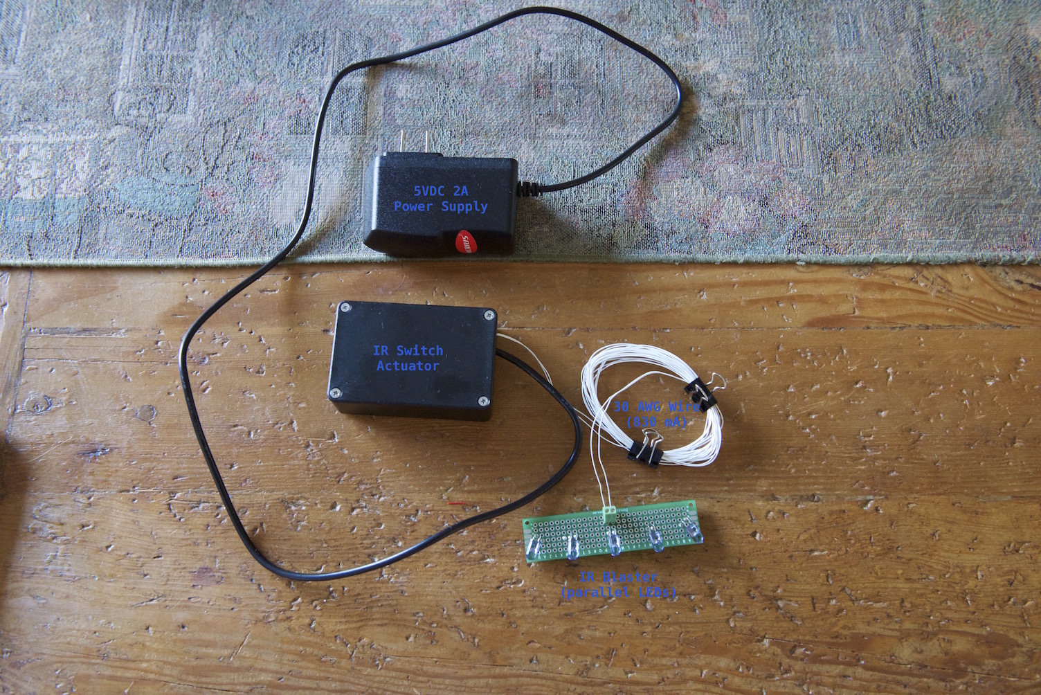
So, my wife loves her Luminara candles that she can turn on and off with a Luminara remote control so heck, why not tie them into the HA system so they come on at sunset and go off when we go to bed each evening? I built a high-power IR blaster, ginned up a small circuit to decode the Luminara remote control codes using the IRSensor sketch MySensors example provided by @hek, configured the on/off IR codes in the actuator sketch and voila - our Vera 3 is able to control my wife's candles! Video, photos and the sketch are provided below.
Completed IR Switch Actuator
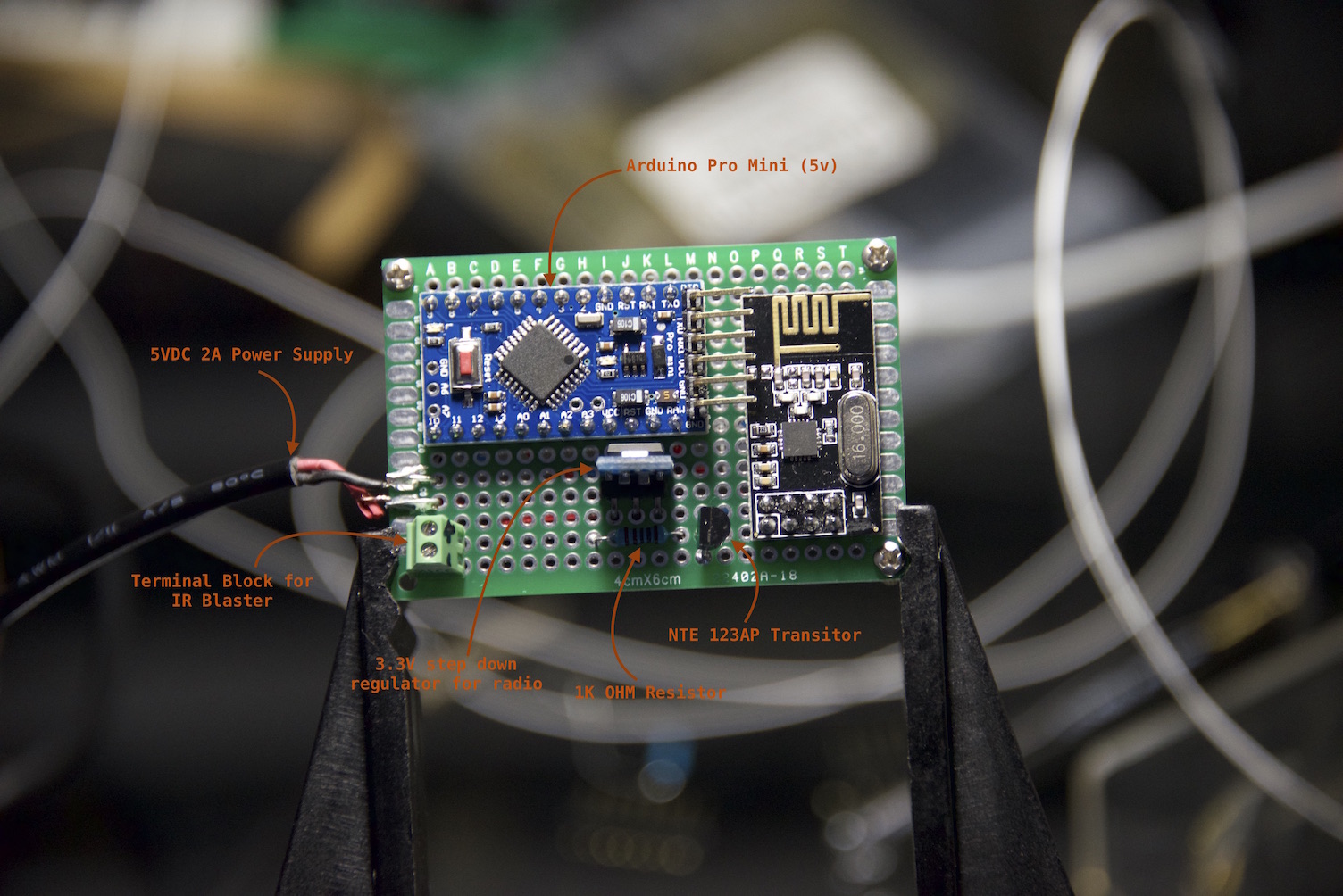
IR Switch Actuator Circuit (top)
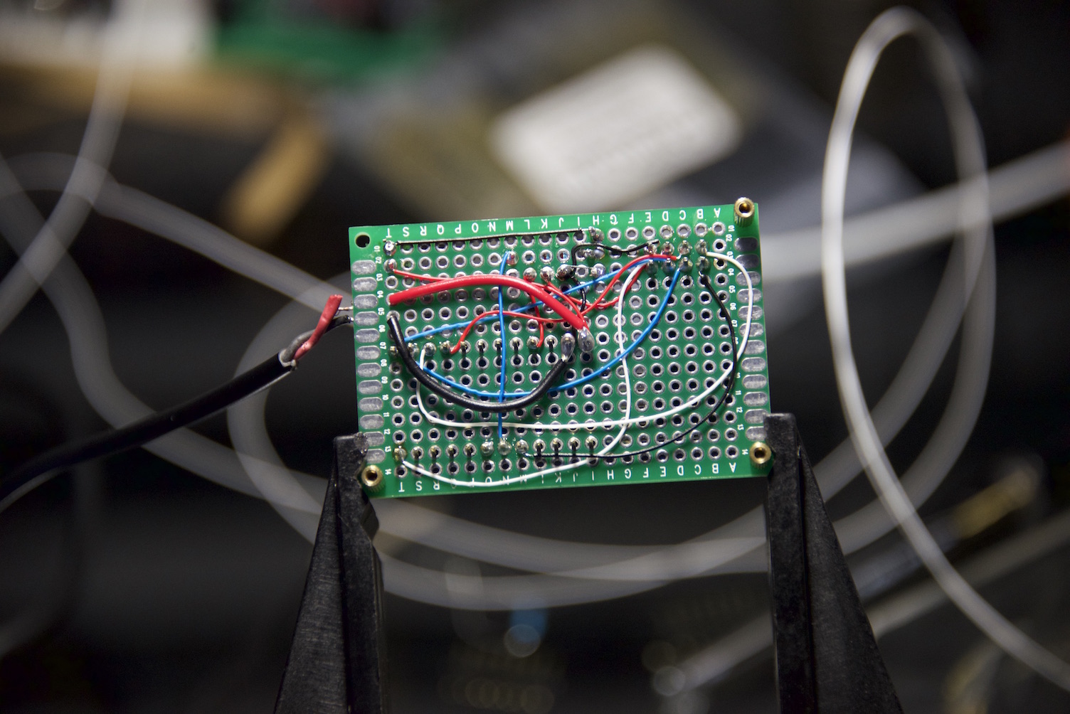
IR Switch Actuator Circuit (bottom) - should probably invest in the convenience boards that others have created to avoid excessive wire-wrapping and soldering ;)
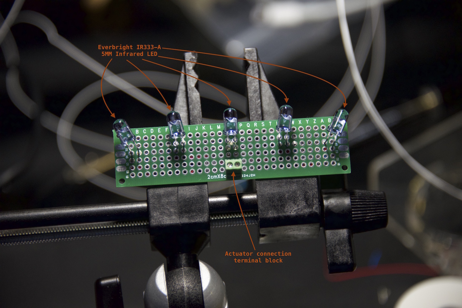
Assembling the IR Blaster - parallel circuit, no forward current resistors to maximize radiant luminance.
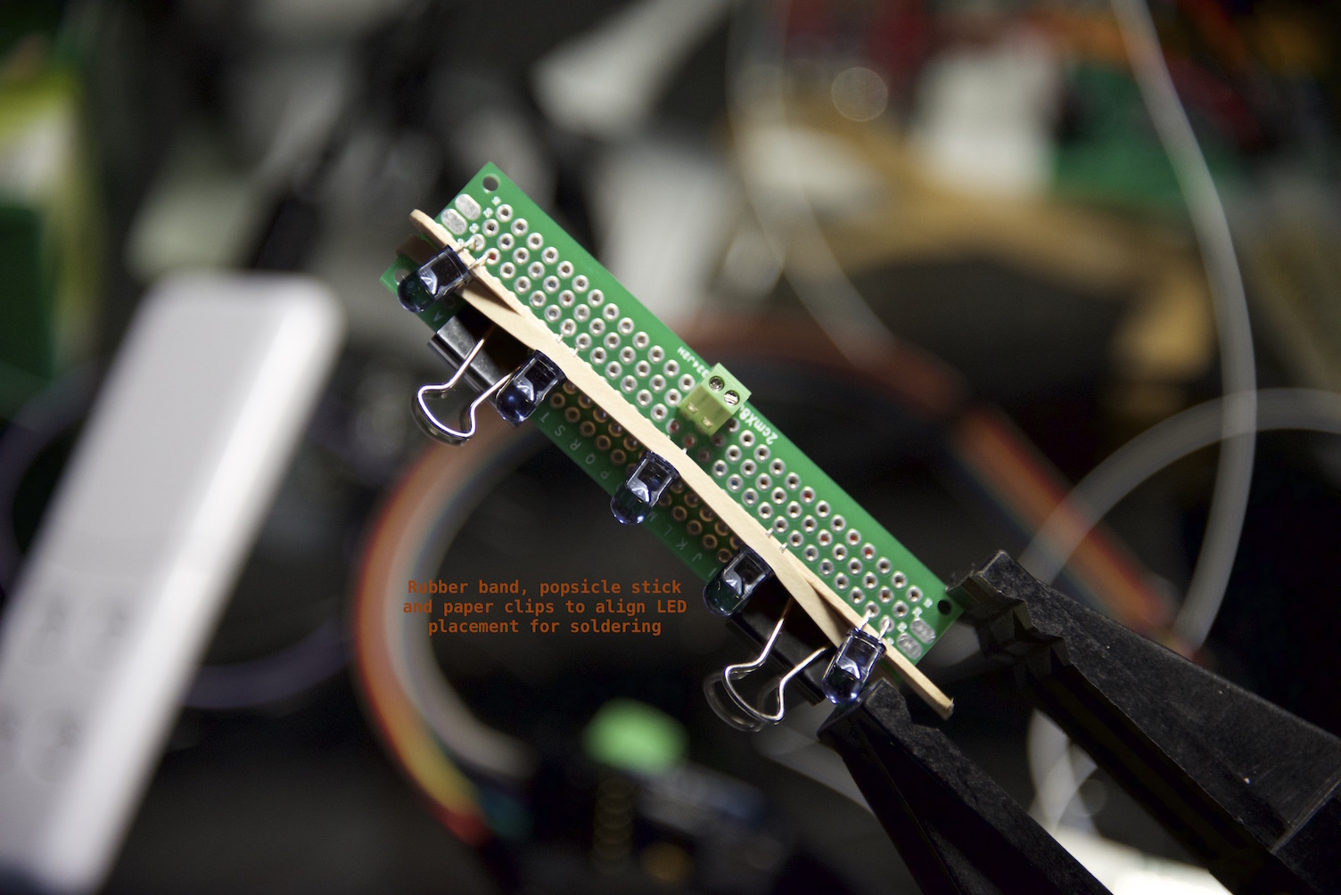
Assembled IR Blaster (top)
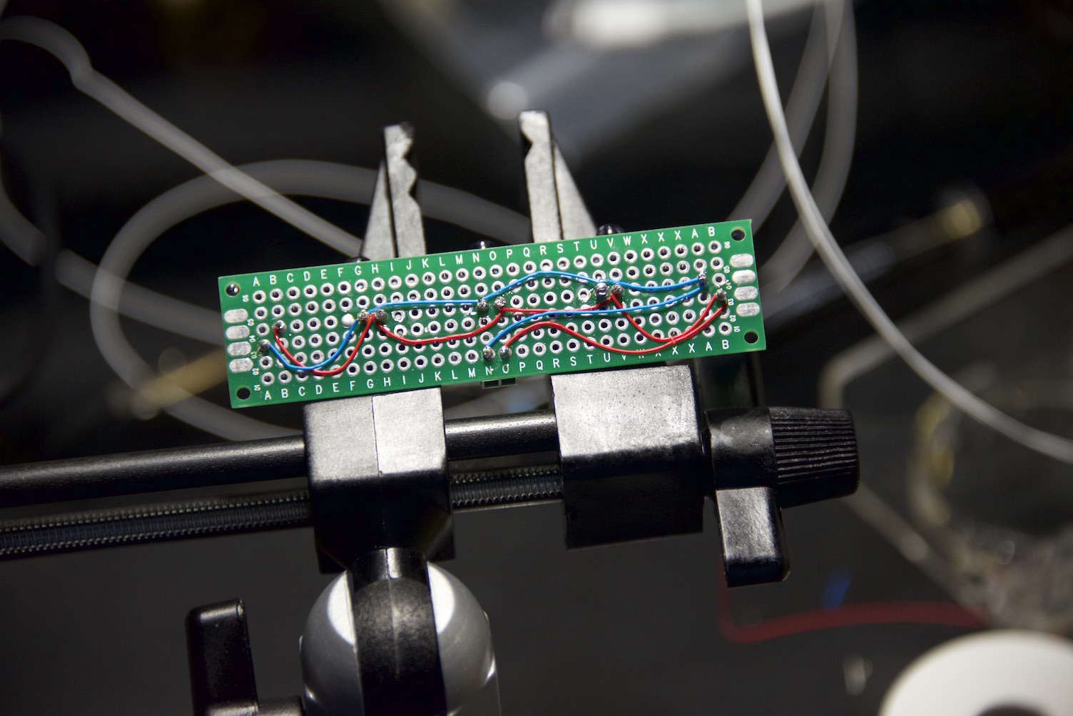
Assembled IR Blaster (bottom)
This was a fun project with a very positive wife factor and I hope others find this useful.
Cheers.
UPDATE (2015-MAY-13) I have started a new thread here to flesh out the design of an official IR Blaster -
-
They use two C-size batteries so they last a very long time. With them on the automation system, I expect them to last at least a year because my wife won't leave them running 24/7 anymore ;) In fact, they may last even longer because the candles will be on less per day as we approach summer because the trigger is tied to sunset... My wife has had the candles just under six months without automation and is still on her first set of batteries.
-
anyone know if you can buy these in europe?
-
@korttoma just bought these yesterday on ebay:
I have no idea if this is something useful
Worth a try for 8 dollar?
-
I just received a couple of these:
http://www.ebay.com/itm/301578035483?_trksid=p2057872.m2749.l2649&ssPageName=STRK%3AMEBIDX%3AIT
Looks like they are the same candles as Luminara but cheaper, time to build the IR Blaster and find out if I can use the sketch @blacey provided straight of.
-
@blacey would you mind sharing how you connected the IR-Transmitters to the arduino? Is this what the Transistor is for?
@korttoma, yes the transistor is used to drive the IR LEDs. It is a standard NPN transistor (NTE123AP) capable of delivering 600mA of current through the collector.
The transistor base lead is connected to the Arduino PWM pin 3 per IRLib, the transistor emitter lead is connected to GND and the transistor collector lead is connected to the IR LED emitters wired in parallel (cathode). It is best practice to place a forward current limiting resistor between IR LEDs anode and VCC but the IRLib drives the LEDs for such short intervals, that you can avoid adding the forward current limiting resistors as I mentioned in the video.
-
Thanks @blacey for the clarification. I sort of overlooked the fact that there was a video, sorry. My consirns was about the current limiting resistor but if you say the IR LEDs can take it I believe you. Thanks again for this project ;)
-
@korttoma - sorry you missed the video ;) I have it on my to-do list to draw a proper schematic for the IR blaster board and the actuator but I just haven't had time yet. I would like to post one in this thread to make it easier for people to build their own IR actuator. Maybe you will get there first ;)
-
Hello @blacey , I got a question... If I'm going to add another IR into the sketch, how do I go about doing this? So two independent sensors into one. This is what I have done so far. Correct me if I'm wrong. Should I be changing something in IRsend irsend ....?
And is your IR LED connected to Pin 1 or Pin3?
/*** * Binary IR Switch sketch that controls Luminara Candles * * Sketch inspired by, and a derivative work of, Hek's IR Sensor example sketch */ #include <MySensor.h> #include <SPI.h> #include <IRLib.h> int RECV_PIN = 8; #define CHILD1 3 // Arduino Pin 3 #define CHILD2 4 // Arduino Pin 4 MySensor gw; MyMessage switchMsg1(CHILD1, V_VAR1); MyMessage switchMsg2(CHILD2, V_VAR1); // IR LED must be connexted to Arduino PWM pin 3 IRsend irsend; #define switchOnIRcode 0x00ff629d // Luminara On IR code #define switchOffIRcode 0x00ffa857 // Luminara Off IR code void setup() { gw.begin(incomingMessage); // Send the sketch version information to the gateway and Controller gw.sendSketchInfo("IR Switch", "1.0"); // Register a sensors to gw. Use binary light for test purposes. gw.present(CHILD1, S_LIGHT); gw.present(CHILD2, S_LIGHT); // Sync switch state to gateway state upon reset / power-up gw.request(CHILD1, V_LIGHT); gw.request(CHILD2, V_LIGHT); } void loop() { gw.process(); } void incomingMessage(const MyMessage &message) { // We only expect one type of message from controller. But we better check anyway. if (message.type==V_LIGHT) { int incomingRelayStatus = message.getInt(); // Emit the IR ON/OFF code irsend.send(NEC, (incomingRelayStatus == 1 ? switchOnIRcode : switchOffIRcode), 32); // Sync gateway of the light switch state gw.send(switchMsg1.set(incomingRelayStatus)); gw.send(switchMsg2.set(incomingRelayStatus)); } } -
Hello @blacey , I got a question... If I'm going to add another IR into the sketch, how do I go about doing this? So two independent sensors into one. This is what I have done so far. Correct me if I'm wrong. Should I be changing something in IRsend irsend ....?
And is your IR LED connected to Pin 1 or Pin3?
/*** * Binary IR Switch sketch that controls Luminara Candles * * Sketch inspired by, and a derivative work of, Hek's IR Sensor example sketch */ #include <MySensor.h> #include <SPI.h> #include <IRLib.h> int RECV_PIN = 8; #define CHILD1 3 // Arduino Pin 3 #define CHILD2 4 // Arduino Pin 4 MySensor gw; MyMessage switchMsg1(CHILD1, V_VAR1); MyMessage switchMsg2(CHILD2, V_VAR1); // IR LED must be connexted to Arduino PWM pin 3 IRsend irsend; #define switchOnIRcode 0x00ff629d // Luminara On IR code #define switchOffIRcode 0x00ffa857 // Luminara Off IR code void setup() { gw.begin(incomingMessage); // Send the sketch version information to the gateway and Controller gw.sendSketchInfo("IR Switch", "1.0"); // Register a sensors to gw. Use binary light for test purposes. gw.present(CHILD1, S_LIGHT); gw.present(CHILD2, S_LIGHT); // Sync switch state to gateway state upon reset / power-up gw.request(CHILD1, V_LIGHT); gw.request(CHILD2, V_LIGHT); } void loop() { gw.process(); } void incomingMessage(const MyMessage &message) { // We only expect one type of message from controller. But we better check anyway. if (message.type==V_LIGHT) { int incomingRelayStatus = message.getInt(); // Emit the IR ON/OFF code irsend.send(NEC, (incomingRelayStatus == 1 ? switchOnIRcode : switchOffIRcode), 32); // Sync gateway of the light switch state gw.send(switchMsg1.set(incomingRelayStatus)); gw.send(switchMsg2.set(incomingRelayStatus)); } }@jeylites My IR LEDs are connected to Pin 3 because that is what IR Lib requires. Your sketch looks close but you will need to define separate switchOnIRcode and switchOffIRcode codes for your respective lights. Then in the incomingMessage loop, send the appropriate code based upon the child ID. If you plan to have a large number of child IDs, I would create an array indexed by child ID to hold the on/off IR codes and then simply invoke ir.send() passing the onOffCode[childID] to it. Does that make sense?
Also, I just started another thread for an official IR Blaster board that you might want to review. I plan to provide multiple device support out of the box...
-
Hello! It looks like you're interested in this conversation, but you don't have an account yet.
Getting fed up of having to scroll through the same posts each visit? When you register for an account, you'll always come back to exactly where you were before, and choose to be notified of new replies (either via email, or push notification). You'll also be able to save bookmarks and upvote posts to show your appreciation to other community members.
With your input, this post could be even better 💗
Register Login