
DIY RFM69 Build
-
Hi,
After using serveral COTS RFM69HW modules I want to build one DIY. The reason is .... space. Building a DIY module is smaller then a COTS one. With a manufactured PCB is can make a difference in space.
After studing the RF69 datasheet I have a question. If you look in the datasheet at figure 42 and the layout of the COTS module there is a difference. The datashee shows the schematic of a HW implementation and the picture attached the COTS implementation. You can see the COTS implementation has a N83 (I suspect a transistor) and a G4C (dont know what that is).
Does anyone know what the purpose is of these 2 components (N83 and G4C). I guess the N83 is for the 130mA power for the boost transmit. But the G4C ...?
Thanks in advance.
/Willem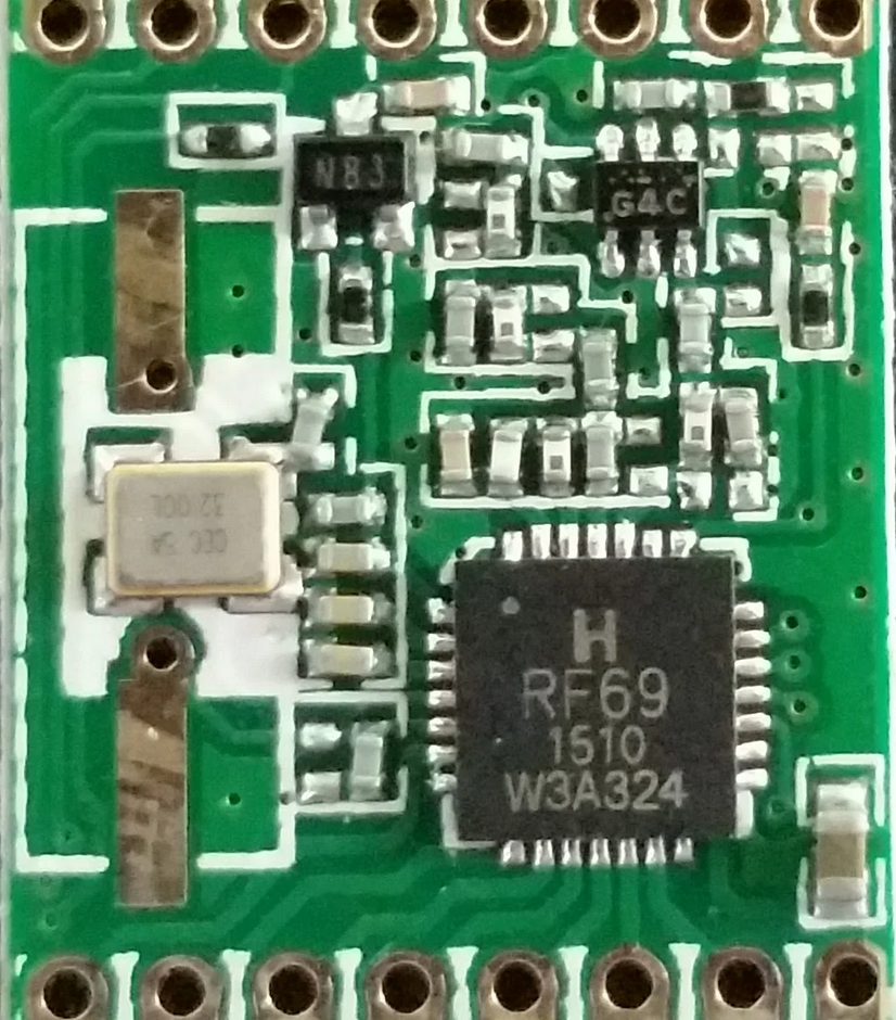
-
Hello
Have you seen this thread ? Thery talk about G4C .
https://lowpowerlab.com/forum/rf-range-antennas-rfm69-library/designing-a-better-rfm69-radio-module/Here is other informations about GaAs
https://www.psemi.com/pdf/app_notes/an18.pdfNot sure to have understood everything :)
Hello! It looks like you're interested in this conversation, but you don't have an account yet.
Getting fed up of having to scroll through the same posts each visit? When you register for an account, you'll always come back to exactly where you were before, and choose to be notified of new replies (either via email, or push notification). You'll also be able to save bookmarks and upvote posts to show your appreciation to other community members.
With your input, this post could be even better 💗
Register Login