DIY RFM69 Build
-
Hi,
After using serveral COTS RFM69HW modules I want to build one DIY. The reason is .... space. Building a DIY module is smaller then a COTS one. With a manufactured PCB is can make a difference in space.
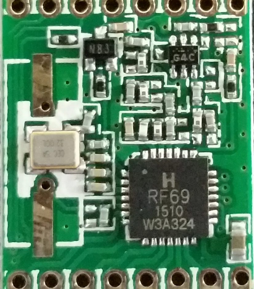
After studing the RF69 datasheet I have a question. If you look in the datasheet at figure 42 and the layout of the COTS module there is a difference. The datashee shows the schematic of a HW implementation and the picture attached the COTS implementation. You can see the COTS implementation has a N83 (I suspect a transistor) and a G4C (dont know what that is).
Does anyone know what the purpose is of these 2 components (N83 and G4C). I guess the N83 is for the 130mA power for the boost transmit. But the G4C ...?
Thanks in advance.
/Willem
-
Hello
Have you seen this thread ? Thery talk about G4C .
https://lowpowerlab.com/forum/rf-range-antennas-rfm69-library/designing-a-better-rfm69-radio-module/Here is other informations about GaAs
https://www.psemi.com/pdf/app_notes/an18.pdfNot sure to have understood everything :)
