Skip to content
  • MySensors
  • OpenHardware.io
  • Categories
  • Recent
  • Tags
  • Popular
Skins
  • Light
  • Brite
  • Cerulean
  • Cosmo
  • Flatly
  • Journal
  • Litera
  • Lumen
  • Lux
  • Materia
  • Minty
  • Morph
  • Pulse
  • Sandstone
  • Simplex
  • Sketchy
  • Spacelab
  • United
  • Yeti
  • Zephyr
  • Dark
  • Cyborg
  • Darkly
  • Quartz
  • Slate
  • Solar
  • Superhero
  • Vapor

  • Default (No Skin)
  • No Skin
Collapse
Brand Logo
  1. Home
  2. Hardware
  3. CR2032 coin cells - expected life?

CR2032 coin cells - expected life?

Scheduled Pinned Locked Moved Hardware
15 Posts 10 Posters 222 Views 9 Watching
  • Oldest to Newest
  • Newest to Oldest
  • Most Votes
Reply
  • Reply as topic
Log in to reply
This topic has been deleted. Only users with topic management privileges can see it.
  • NeverDieN NeverDie

    When are you measuring the battery voltage? Before or after a transmission? My guess is before. The better measurement is if you measure immediately after transmission, before battery recovery, and then save the value for reporting during the next subsequent transmission. That's especially true for coincells, whose voltage tends to droop a lot after pulling a current.

    sundberg84S Offline
    sundberg84S Offline
    sundberg84
    Hardware Contributor
    wrote on last edited by
    #5

    @NeverDie - I measure after - but I let the battery recover from the transmission, so you have a valid point.
    @BearWithBeard - Thanks - if you can do it, I can :)
    @ncollins - a big capasitor sounds lika a good idea, 1.8v bod I have and also sleep (5 minutes). Thanks for the input, sounds like a plan ahead.

    Controller: Proxmox VM - Home Assistant
    MySensors GW: Arduino Uno - W5100 Ethernet, Gw Shield Nrf24l01+ 2,4Ghz
    MySensors GW: Arduino Uno - Gw Shield RFM69, 433mhz
    RFLink GW - Arduino Mega + RFLink Shield, 433mhz

    1 Reply Last reply
    0
    • nagelcN Offline
      nagelcN Offline
      nagelc
      wrote on last edited by nagelc
      #6

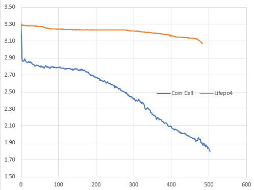
      I recently completed an experiment with 2 nearly identical nodes and had very good results just using @NeverDie MySleepPrepare() without any other real effort to reduce power consumption.
      The nodes were NRF52832 and BME280. One with a CR2032 Coin cell and the other with a LiFePo4 (AAA size). The CR2032 lasted a little longer in this application.
      I stopped when the CR2032 dropped below 1.8V because that was the low voltage rating for both the processor and the BME, but the node still appeared to be working normally.

      Vertical axis is volts. Horizontal axis is days.
      6988a0a4-aec8-454b-92ce-5b424525f399-image.png

      skywatchS 1 Reply Last reply
      2
      • nagelcN nagelc

        I recently completed an experiment with 2 nearly identical nodes and had very good results just using @NeverDie MySleepPrepare() without any other real effort to reduce power consumption.
        The nodes were NRF52832 and BME280. One with a CR2032 Coin cell and the other with a LiFePo4 (AAA size). The CR2032 lasted a little longer in this application.
        I stopped when the CR2032 dropped below 1.8V because that was the low voltage rating for both the processor and the BME, but the node still appeared to be working normally.

        Vertical axis is volts. Horizontal axis is days.
        6988a0a4-aec8-454b-92ce-5b424525f399-image.png

        skywatchS Offline
        skywatchS Offline
        skywatch
        wrote on last edited by skywatch
        #7

        @nagelc Just wondering what boards and what bootloaders you are all using for battery nodes as I will need to make a few soon.

        nagelcN 1 Reply Last reply
        0
        • skywatchS skywatch

          @nagelc Just wondering what boards and what bootloaders you are all using for battery nodes as I will need to make a few soon.

          nagelcN Offline
          nagelcN Offline
          nagelc
          wrote on last edited by
          #8

          @skywatch These used the Fanstel BT832. Not sure about the bootloader. I just programmed them as they came. I programmed them using Arduino and the MySensors MyBoardNRF5 files, and a black magic probe for the programmer.

          skywatchS 1 Reply Last reply
          0
          • nagelcN nagelc

            @skywatch These used the Fanstel BT832. Not sure about the bootloader. I just programmed them as they came. I programmed them using Arduino and the MySensors MyBoardNRF5 files, and a black magic probe for the programmer.

            skywatchS Offline
            skywatchS Offline
            skywatch
            wrote on last edited by
            #9

            @nagelc Thanks for the clarification.

            1 Reply Last reply
            0
            • B Offline
              B Offline
              buxtronix
              wrote on last edited by
              #10

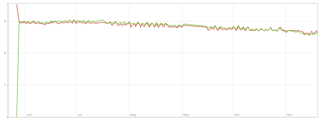
              I've been doing an experiment based on my custom board (https://github.com/buxtronix/mys-pro-mini) which is essentially an Arduino-pro-mini compatible pinout with NRF radio and SHT31 temp/humidity sensor built in.

              It can take a CR2032 directly on board.

              I've been running two identical sensors, the only difference being that one uses the INTRC clock, and the other uses an 8MHz Xtal. Update rate is about 1/min.
              Screenshot from 2021-11-20 08-52-40.png

              As you can see, I'm nearly 6 months in and I think I should be able to get to a year. Interestingly, there is no notable difference in battery between the two clock sources - it's otherwise been widely believed that xtal consumes more power than intrc.

              The only low-power prep I'm doing in the code is to disable the ADC and set all unused floating pins to output mode. Standard arduino bootloader, BOD disabled.

              mfalkviddM 1 Reply Last reply
              1
              • B buxtronix

                I've been doing an experiment based on my custom board (https://github.com/buxtronix/mys-pro-mini) which is essentially an Arduino-pro-mini compatible pinout with NRF radio and SHT31 temp/humidity sensor built in.

                It can take a CR2032 directly on board.

                I've been running two identical sensors, the only difference being that one uses the INTRC clock, and the other uses an 8MHz Xtal. Update rate is about 1/min.

                Screenshot from 2021-11-20 08-52-40.png

                As you can see, I'm nearly 6 months in and I think I should be able to get to a year. Interestingly, there is no notable difference in battery between the two clock sources - it's otherwise been widely believed that xtal consumes more power than intrc.

                The only low-power prep I'm doing in the code is to disable the ADC and set all unused floating pins to output mode. Standard arduino bootloader, BOD disabled.

                mfalkviddM Offline
                mfalkviddM Offline
                mfalkvidd
                Mod
                wrote on last edited by
                #11

                Great info @buxtronix, thanks for sharing.
                When do you measure the battery voltage? Just after wakeup, just before going back to sleep or somewhere between?

                1 Reply Last reply
                0
                • C Offline
                  C Offline
                  canyouhearmenow
                  wrote on last edited by
                  #12

                  Good idea to measure battery voltage after an RF transmission, not before ... never thought of that.

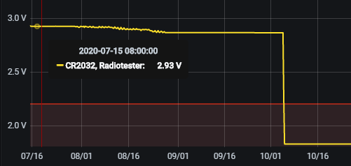
                  I have built window sensors that last more than 36 months on one CR2032. I usually set the brownout threshold to 1.8V, not 2.7V, and then replace the battery when the voltage drops below ~2.2V.

                  You have to be careful not to power any sensors while the node is asleep, that also applies to the lowly reed switch windows sensor! If you just connect it to an input pin and use the internal pull-up of the ATmega processor, then you have a current flowing all the time, when the window is closed and therefore the reed switch inside the sensor is closed. That current is higher than the sleep mode power consumption of the whole processor!

                  I can see why internal clock vs 8 MHz crystal doesn't make a difference -- most of the time, the processor will be asleep with all clocks stopped, and a stopped 8 MHz crystal oscillator consumes as much power as a stopped internal RC oscillator ...

                  You can find more details about what to watch out for, and some measurements with different configurations, here.

                  1 Reply Last reply
                  1
                  • Michiel van der WulpM Offline
                    Michiel van der WulpM Offline
                    Michiel van der Wulp
                    wrote on last edited by
                    #13

                    @canyouhearmenow : in stead of the internal pull-up resistor for the reed contact, I used an external one of 3.3MOhm. Is that a good idea?

                    C 1 Reply Last reply
                    0
                    • B Offline
                      B Offline
                      buxtronix
                      wrote on last edited by
                      #14

                      @Michiel-van-der-Wulp

                      An alternative is to do pullup via an output pin. So connect the switch like this:

                      D2 --- 47k --- D1 --- reed switch --- GND

                      Disable D1's pullups. While sleeping set D2 low to eliminate all power draw, then after wakeup you can set D2 high, wait a few ms and then measure D1. Once done, set D2 low again.

                      You can't do interrupt based sensing this way but works for polling.

                      1 Reply Last reply
                      0
                      • Michiel van der WulpM Michiel van der Wulp

                        @canyouhearmenow : in stead of the internal pull-up resistor for the reed contact, I used an external one of 3.3MOhm. Is that a good idea?

                        C Offline
                        C Offline
                        canyouhearmenow
                        wrote on last edited by
                        #15

                        @Michiel-van-der-Wulp using a megaohms pull-up resistor solves the problem with current consumption, but now you have an input that is more susceptible to interference, because it is high impedance.

                        1 Reply Last reply
                        0
                        Reply
                        • Reply as topic
                        Log in to reply
                        • Oldest to Newest
                        • Newest to Oldest
                        • Most Votes


                        25

                        Online

                        11.7k

                        Users

                        11.2k

                        Topics

                        113.1k

                        Posts


                        Copyright 2025 TBD   |   Forum Guidelines   |   Privacy Policy   |   Terms of Service
                        • Login

                        • Don't have an account? Register

                        • Login or register to search.
                        • First post
                          Last post
                        0
                        • MySensors
                        • OpenHardware.io
                        • Categories
                        • Recent
                        • Tags
                        • Popular