Anyone using/tried the E28-2G4M27S 2.4Ghz LoRa SX1280 27dB module?
-
@NeverDie : Very interesting stuff. Even at the lowly 8MHz, the speed of processing pretty much blows away the human concept of time. Fun to hear of the Raspberry and Due. I’ll have to play with those.
HT12D/HT12E: Yes, I learned that the processing could be done on a MCU and I did that on the repeaters I built. I put a Pro-Mini in between a 433 Mhz RX and TX. This repeater sits and listens in the RX mode until it is pinged with a transmission from one of the 433-HT12E detectors. Once a message comes in, the MCU then switches to TX mode and passes the message along, then reverts to listening again. The repeaters and the base station are mains powered as I figured the always ON state would be a battery killer whereas the 433-HT12E’s are very low power and outfitted with batteries.
Rather than using the IIRC library I used RCSwitch – probably because I found that first. RadioHead was another option. The biggest challenge for me was learning which protocol to use for the 433 radios. The command mySwitch.setProtocol(11); did the trick.
@Larson The Due has an 84Mhz clock speed, making it easier to spot the effect. These days you could save some coin by using an ESP8266 (80Mhz) or even faster ESP-32, not to mention the crazy fast Teensy 4.1 (600Mhz). At 600Mhz, light moves only 20 inches per clock cycle. Pretty cool for cheap parts, isn't it? :-)
-
I received the Dorji parts I had ordered. They arrived very fast and very well packed. I got them on ebay, but for comparison I'm still waiting on everything else that I had ordered from aliexpress.
It turns out it took 3 days for JLCPCB to build my simple 2 layer PCB's. Either they're overwhelmed with business or understaffed. With any luck they'll ship out tomorrow, so probably another week to get here.
Meanwhile I received a Nord PPK2 Power Profiler, as I found a seller who briefly had some in stock. So, I'll be putting that to use to accurately compare current consumption of the various test builds after the PCBs eventually arrive from JLPCB. Meanwhile, I may try it out on an ESP8266 to finally get some solid current consumption numbers on how much power it takes to wake-up into ESP-NOW mode from a cold start. If it's good, then maybe so-called trigger boards will bring the ESP8266 back to life as a low power competitor. Also, I'm really curious as to how sensitive (or not) the ESP8266 2.4Ghz ESP-NOW communications will be to interference in a home environment that, at least so far, seems to have shredded 2.4Ghz LoRa. According to the labeling on the tin, they come with 25dBa power amplifiers, so I expect they'll do far better than a bog standard nRF24L01, which has a maximum of only just 0dBa transmit power. Of course, when you add in the cost of a trigger board, then total cost may (?) turn out to be a wash compared to other mcu/radio combos that don't require a trigger board. We'll see!
-
@samh Great stuff! I look forward to hearing more. As you probably know, the buck/boost converter (whichever it is) that's in your photo is a possible source of noise. I can't say whether, in reality, it would be or not. That's one of the reasons why (below), I'm planning to run directly from batteries only.
@Larson Good suggestions. I decided to dump the pro mini idea and just make my own barebones pro mini, because pro mini's come with three things that aren't useful and actually get in the way: 1. the LDO, 2. the oscillator, and 3. the LED on pin 13. I'm hoping (but haven't confirmed) that by eliminating the oscillator on pins D20 and D21, I can use those pins to drive two LED's kinda "for free" since nobody uses those pins for anything. So, the first draft looked like this:
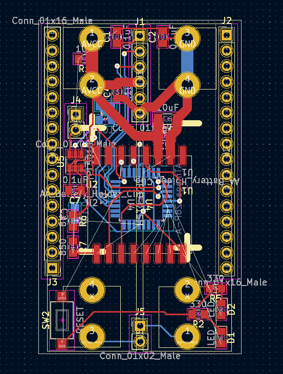
to get the shortest possible lines, like you said. It also includes a TPL5010 as an ultra low current wakeup timer. The main thing, though, is that it runs from two AA batteries, which are directly attached to the PCB itself. Well, this design was working out fine, but it seemed a bit tedious to redo it for each possible radio I wanted to test, so I think I'm settling on this instead as a test platform:
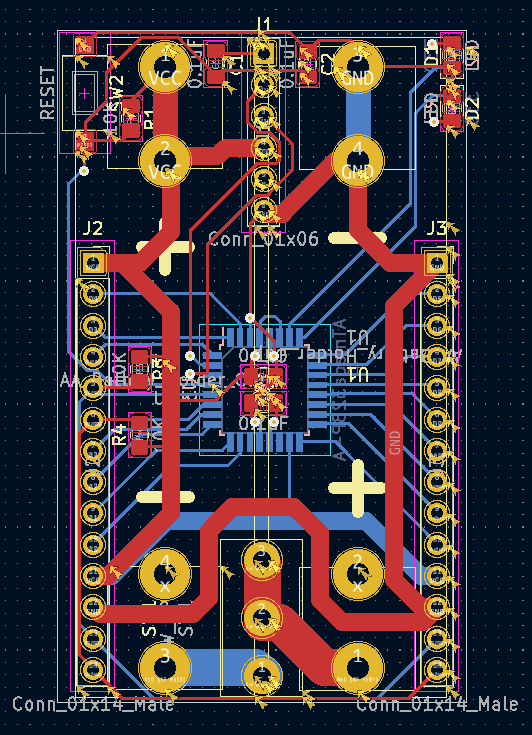
which amounts to a stripped down pro mini (plus two I2C pinsout at the bottom for plugging in a TH sensor, or whatnot). In this case, the idea is to do a simple breakout board for each radio and connect it as a shield to the unused pins on the atmega328p. I figure it should be easier than doing a complete, fully integrated board for each radio. And I like that it's of minimal size (the footprint of two AA batteries), yet packs enough power that I expect it should have no trouble supplying even 200ma if needed just from the batteries themselves.I'm lucky in that I have a Dragon programmer, so I can both burn the bootloader and set the fuses on the atmega328p prior to soldering it into place on the PCB. From past experience, the sleep current on the atmega328p itself can be as low as 100na. In the past when Pro Mini's sold for only a buck, I leaned toward using Pro Mini's for everything. These days I guess I'll roll my own.
I think eventually I want to replace the canonical 6 pin FTDI connection with a 5 pin picoblade. I've only just started looking into that. I was favoring the idea of using 1.0mm pitch JST-SH conectors for the task, but sourcing them didn't look easy. So, I'm reluctantly settling on the 1.25mm pitch picoblade instead. If there exists something even more compact (maybe some kind of 2x3 row of pins on a connector), then I'd be keen to hear what it is.
The AA battery connectors are the Keystone 92, which look like this:

In the end, it might look like an improved variation of one of these:
https://www.openhardware.io/view/395/LoRa-Ra-01-ATmega328P-Node
https://www.openhardware.io/view/268/Arduino-Pro-Mini-Shield-for-RFM69HW
https://www.openhardware.io/view/480/Compact-nRF24L01-Pro-Mini-Bottom-Shield
but this time a bit more of a general purpose razor and blades system, if you catch my meaning. This time it will be a little wider than a pro mini, so it will be possible to fit any radio onto the shield. That said, I always liked the simplicity and ease of assembly of the "LoRa Ra-01 ATmega328P node". Perhaps the biggest improvement is the tight integration of the batteries, which in most designs are left "flapping in the breeze" as an afterthought for the builder to sort out.Anyhow, I have a bit more work to do, but that's the current evolution. As always, any thoughts, reactions, suggestions, or feedback appreciated.
@NeverDie said in Anyone using/tried the E28-2G4M27S 2.4Ghz LoRa SX1280 27dB module?:
I'm hoping (but haven't confirmed) that by eliminating the oscillator on pins D20 and D21, I can use those pins to drive two LED's kinda "for free" since nobody uses those pins for anything.
Reporting back: I have the answer. It turns out that the standard arduino core for atmega328p that's baked into the standard Arduino IDE does not support Arduino pins 20 and 21 as digital GPIO pins for driving LEDs. However, the good news is that there's an even better Arduino core, called MCUDude MiniCore which does support exactly those pins for such purposes. Here's the TL;DR:
This core gives you two extra IO pins if you're using the internal oscillator! PB6 and PB7 is mapped to Arduino pin 20 and 21.
https://mcudude.github.io/MiniCore/package_MCUdude_MiniCore_index.json
It's very easy to use. You can install it into the regular Arduino IDE, pick from among the MiniCore "boards" in the board manager, select the 8Mhz option and a few other obvious options, and then you're done with instalation. From that point on your code will automagically compile using MiniCore. Just to be sure, I gave it a try myself, and I'm now blinking a blue LED off of Ardino Pin 20. It works! -
@NeverDie said in Anyone using/tried the E28-2G4M27S 2.4Ghz LoRa SX1280 27dB module?:
I'm hoping (but haven't confirmed) that by eliminating the oscillator on pins D20 and D21, I can use those pins to drive two LED's kinda "for free" since nobody uses those pins for anything.
Reporting back: I have the answer. It turns out that the standard arduino core for atmega328p that's baked into the standard Arduino IDE does not support Arduino pins 20 and 21 as digital GPIO pins for driving LEDs. However, the good news is that there's an even better Arduino core, called MCUDude MiniCore which does support exactly those pins for such purposes. Here's the TL;DR:
This core gives you two extra IO pins if you're using the internal oscillator! PB6 and PB7 is mapped to Arduino pin 20 and 21.
https://mcudude.github.io/MiniCore/package_MCUdude_MiniCore_index.json
It's very easy to use. You can install it into the regular Arduino IDE, pick from among the MiniCore "boards" in the board manager, select the 8Mhz option and a few other obvious options, and then you're done with instalation. From that point on your code will automagically compile using MiniCore. Just to be sure, I gave it a try myself, and I'm now blinking a blue LED off of Ardino Pin 20. It works!@NeverDie More good information - thanks for posting. Good work on finding the alternate core. I have a couple of questions:
- By “trigger board”, are you referring to the TPL5010 discussed above? (Adafruit carries the TPL5110, I think.) Is the idea here to power and de-power the radio, or mcu, to discover the rock-bottom minimum current requirement?
- What are you sacrificing when not using the external crystal? And to do this, are you setting fuses to tell the 328 to use the internal crystal? I've found setting fuses to be a complicated affair.
-
@Larson The Due has an 84Mhz clock speed, making it easier to spot the effect. These days you could save some coin by using an ESP8266 (80Mhz) or even faster ESP-32, not to mention the crazy fast Teensy 4.1 (600Mhz). At 600Mhz, light moves only 20 inches per clock cycle. Pretty cool for cheap parts, isn't it? :-)
@NeverDie said in Anyone using/tried the E28-2G4M27S 2.4Ghz LoRa SX1280 27dB module?:
At 600Mhz, light moves only 20 inches per clock cycle. Pretty cool for cheap parts, isn't it?
Yes, mind-blowing. I got into this hobby via the Parallax Basic kits. The second MCU I bought from them was about $60 and I thought that was stunning. So when I found the ATTINY85 I was addicted, if only because the access to this technology costs less than a cup of coffee. The progression to Arduinos and ESP's was a natural extension for this cheap hobby.
-
@NeverDie More good information - thanks for posting. Good work on finding the alternate core. I have a couple of questions:
- By “trigger board”, are you referring to the TPL5010 discussed above? (Adafruit carries the TPL5110, I think.) Is the idea here to power and de-power the radio, or mcu, to discover the rock-bottom minimum current requirement?
- What are you sacrificing when not using the external crystal? And to do this, are you setting fuses to tell the 328 to use the internal crystal? I've found setting fuses to be a complicated affair.
@Larson said in Anyone using/tried the E28-2G4M27S 2.4Ghz LoRa SX1280 27dB module?:
@NeverDie More good information - thanks for posting. Good work on finding the alternate core. I have a couple of questions:
-
By “trigger board”, are you referring to the TPL5010 discussed above? (Adafruit carries the TPL5110, I think.) Is the idea here to power and de-power the radio, or mcu, to discover the rock-bottom minimum current requirement? - What are you sacrificing when not using the external crystal? And to do this, are you setting fuses to tell the 328 to use the internal crystal? I've found setting fuses to be a complicated affair.
Good questions!
- Yes, by "trigger board", the adafruit tpl5110, or something like it, is what I have in mind. The goal would be zero leakage current beyond the ~40 nanoamps of management overhead. I don't know if the p-channel mosfet design in adafruit's tpl5110 breakout board achieves zero leakage (or near enough),but it would be worth measuring. I think Kevin Darrah may be the one who coined the term "trigBoard". His design is a lot more elaborate and, I assume, costly: https://www.kevindarrah.com/wiki/index.php?title=TrigBoardV7
Is the idea here to power and de-power the radio, or mcu, to discover the rock-bottom minimum current requirement?
Yes. It's a little more complicated though, because generally the mcu/radio wake-up time is much longer from a cold start than from a deep sleep, so the real objective would be to find the breakeven point at which power-off is the better choice (i.e. how long does the duty cycle need to be).
What are you sacrificing when not using the external crystal?
Accuracy. If you were interfacing to something that had extremely tight timing requirements, the crystal would be more accurate. In practice, I haven't ever noticed a difference in anything that I've done.
And to do this, are you setting fuses to tell the 328 to use the internal crystal? I've found setting fuses to be a complicated affair.
Yes, I set the fuses. Currently I use the following fuse settings:
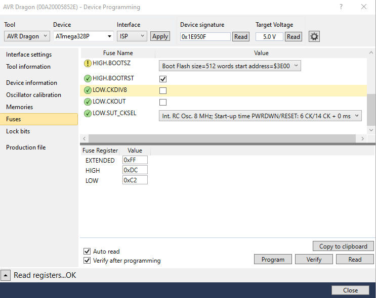
By running from the 8Mhz internal oscillator and sleeping, not only can you sleep the atmega328p at just 100na, but as a bonus the atmega328p can wake up in just 3 microseconds (I previously measured it with an oscilloscope, so that number is solid). For being such an old mcu, the atmega328p can be amazingly high performance when it comes to saving power. This becomes of greater relevance if you're getting your power by harvesting weak energy sources.If you want to play around with setting fuse bits, the standard advice is to leave the Extended bits alone until you know what you're doing. Even then, there's probably no need to change them. It's the High and Low bits that are of relevance.
A great source of information is: https://www.gammon.com.au/power
-
@Larson said in Anyone using/tried the E28-2G4M27S 2.4Ghz LoRa SX1280 27dB module?:
@NeverDie More good information - thanks for posting. Good work on finding the alternate core. I have a couple of questions:
-
By “trigger board”, are you referring to the TPL5010 discussed above? (Adafruit carries the TPL5110, I think.) Is the idea here to power and de-power the radio, or mcu, to discover the rock-bottom minimum current requirement? - What are you sacrificing when not using the external crystal? And to do this, are you setting fuses to tell the 328 to use the internal crystal? I've found setting fuses to be a complicated affair.
Good questions!
- Yes, by "trigger board", the adafruit tpl5110, or something like it, is what I have in mind. The goal would be zero leakage current beyond the ~40 nanoamps of management overhead. I don't know if the p-channel mosfet design in adafruit's tpl5110 breakout board achieves zero leakage (or near enough),but it would be worth measuring. I think Kevin Darrah may be the one who coined the term "trigBoard". His design is a lot more elaborate and, I assume, costly: https://www.kevindarrah.com/wiki/index.php?title=TrigBoardV7
Is the idea here to power and de-power the radio, or mcu, to discover the rock-bottom minimum current requirement?
Yes. It's a little more complicated though, because generally the mcu/radio wake-up time is much longer from a cold start than from a deep sleep, so the real objective would be to find the breakeven point at which power-off is the better choice (i.e. how long does the duty cycle need to be).
What are you sacrificing when not using the external crystal?
Accuracy. If you were interfacing to something that had extremely tight timing requirements, the crystal would be more accurate. In practice, I haven't ever noticed a difference in anything that I've done.
And to do this, are you setting fuses to tell the 328 to use the internal crystal? I've found setting fuses to be a complicated affair.
Yes, I set the fuses. Currently I use the following fuse settings:
By running from the 8Mhz internal oscillator and sleeping, not only can you sleep the atmega328p at just 100na, but as a bonus the atmega328p can wake up in just 3 microseconds (I previously measured it with an oscilloscope, so that number is solid). For being such an old mcu, the atmega328p can be amazingly high performance when it comes to saving power. This becomes of greater relevance if you're getting your power by harvesting weak energy sources.If you want to play around with setting fuse bits, the standard advice is to leave the Extended bits alone until you know what you're doing. Even then, there's probably no need to change them. It's the High and Low bits that are of relevance.
A great source of information is: https://www.gammon.com.au/power
@NeverDie said in Anyone using/tried the E28-2G4M27S 2.4Ghz LoRa SX1280 27dB module?:
sleep the atmega328p at just 100na
Wow, that is pretty close to zero in my view. Consider battery self-discharge in comparison: I use 18650 LiOn batteries in most of my projects. Say a 2000 mAh battery loses 1%/month in self discharge s(ome say it is much higher). Well, the math, if I did it right, shows a self-discharge of about 25 uA. So sleeping at 100nA is really impressive.
Thanks for the fuse guidance. I will employ this next chance I get.
-
-
@NeverDie said in Anyone using/tried the E28-2G4M27S 2.4Ghz LoRa SX1280 27dB module?:
sleep the atmega328p at just 100na
Wow, that is pretty close to zero in my view. Consider battery self-discharge in comparison: I use 18650 LiOn batteries in most of my projects. Say a 2000 mAh battery loses 1%/month in self discharge s(ome say it is much higher). Well, the math, if I did it right, shows a self-discharge of about 25 uA. So sleeping at 100nA is really impressive.
Thanks for the fuse guidance. I will employ this next chance I get.
@Larson Yes. The RFM69 can also be slept at just 100na, so taken together they are an awesome duo. If you're running from 2xAA batteries, then the the combined 200na are essentially zero. If, in contrast, you're trying to harvest energy from a small solar cell in an indoor environment that's dimly lit by LED lighting only rarely, then it becomes more relevant.
Anyhow, I've noticed that a lot of people measure very small currents incorrectly, so just trying to find answers on the internet, which is full of wrong measurements, isn't easy. Datasheets can provide some insight.
-
@Larson Yes. The RFM69 can also be slept at just 100na, so taken together they are an awesome duo. If you're running from 2xAA batteries, then the the combined 200na are essentially zero. If, in contrast, you're trying to harvest energy from a small solar cell in an indoor environment that's dimly lit by LED lighting only rarely, then it becomes more relevant.
Anyhow, I've noticed that a lot of people measure very small currents incorrectly, so just trying to find answers on the internet, which is full of wrong measurements, isn't easy. Datasheets can provide some insight.
@NeverDie Yes, the experience and knowledge found by doing (measuring) is always deeper,
Forgot to mention: Kevin Darah. I have bought several of his TrigBoards. I find the price to be a good value for the design, components, assembly, and all the content he has posted. The quality of his boards is great. I am a Patreon of his. I just need to play with the TrigBoards some more.
-
@NeverDie Yes, the experience and knowledge found by doing (measuring) is always deeper,
Forgot to mention: Kevin Darah. I have bought several of his TrigBoards. I find the price to be a good value for the design, components, assembly, and all the content he has posted. The quality of his boards is great. I am a Patreon of his. I just need to play with the TrigBoards some more.
@Larson said in Anyone using/tried the E28-2G4M27S 2.4Ghz LoRa SX1280 27dB module?:
@NeverDie Yes, the experience and knowledge found by doing (measuring) is always deeper,
Forgot to mention: Kevin Darah. I have bought several of his TrigBoards. I find the price to be a good value for the design, components, assembly, and all the content he has posted. The quality of his boards is great. I am a Patreon of his. I just need to play with the TrigBoards some more.
I'd be interested to hear your thoughts on Kevin's trigBoards after you've had a chance to get familiar with them. A compare/contrast of his board to the adafruit board would be even more awesome. The adafruit board is a very simple design and would cost less than $1 in parts if you were to source them yourself. I suppose its main limitation is 1. the maximum sleep time is two hours, and 2. not as accurate as a proper RTC. In its favor is that at 40na the sleep current consumption is next to nothing. On the other hand, some RTCs have a sleep current less than 1ua, so maybe that's good enough.
-
@Larson said in Anyone using/tried the E28-2G4M27S 2.4Ghz LoRa SX1280 27dB module?:
@NeverDie Yes, the experience and knowledge found by doing (measuring) is always deeper,
Forgot to mention: Kevin Darah. I have bought several of his TrigBoards. I find the price to be a good value for the design, components, assembly, and all the content he has posted. The quality of his boards is great. I am a Patreon of his. I just need to play with the TrigBoards some more.
I'd be interested to hear your thoughts on Kevin's trigBoards after you've had a chance to get familiar with them. A compare/contrast of his board to the adafruit board would be even more awesome. The adafruit board is a very simple design and would cost less than $1 in parts if you were to source them yourself. I suppose its main limitation is 1. the maximum sleep time is two hours, and 2. not as accurate as a proper RTC. In its favor is that at 40na the sleep current consumption is next to nothing. On the other hand, some RTCs have a sleep current less than 1ua, so maybe that's good enough.
@NeverDie said in Anyone using/tried the E28-2G4M27S 2.4Ghz LoRa SX1280 27dB module?:
In its favor is that at 40na the sleep current...
I'll order several. Then compare to the TrigBoards. Adafruit's TPL5011 advertises a run current of 20uA. Is that acceptable for you? If so I'll buy several. Couple of limitations for me: 1. Time - I'm about a month out, 2. My Ammeter is a standard DMM from Harbor Freight. The smallest range is 200uA and I've found it very useful. Certainly fine enough to show the 20uA, but inadequate for nanoAmps.
-
@NeverDie said in Anyone using/tried the E28-2G4M27S 2.4Ghz LoRa SX1280 27dB module?:
In its favor is that at 40na the sleep current...
I'll order several. Then compare to the TrigBoards. Adafruit's TPL5011 advertises a run current of 20uA. Is that acceptable for you? If so I'll buy several. Couple of limitations for me: 1. Time - I'm about a month out, 2. My Ammeter is a standard DMM from Harbor Freight. The smallest range is 200uA and I've found it very useful. Certainly fine enough to show the 20uA, but inadequate for nanoAmps.
@Larson said in Anyone using/tried the E28-2G4M27S 2.4Ghz LoRa SX1280 27dB module?:
@NeverDie said in Anyone using/tried the E28-2G4M27S 2.4Ghz LoRa SX1280 27dB module?:
In its favor is that at 40na the sleep current...
I'll order several. Then compare to the TrigBoards. Adafruit's TPL5011 advertises a run current of 20uA. Is that acceptable for you? If so I'll buy several. Couple of limitations for me: 1. Time - I'm about a month out, 2. My Ammeter is a standard DMM from Harbor Freight. The smallest range is 200uA and I've found it very useful. Certainly fine enough to show the 20uA, but inadequate for nanoAmps.
Hmmmm... Something's wrong then with Adafruit's design if it's 20uA. The chip itself consumes only 35na according to its datasheet:
https://www.ti.com/lit/ds/symlink/tpl5110.pdf?ts=1652658923819&ref_url=https%253A%252F%252Fwww.google.com%252F
Maybe their p-channel mosfet has high leakage current with the circuit has they've designed it? I would pass if it really is 20uA. I'm sure I could do better than that.You need something like either a Current Ranger or a MicroCurrent Gold to accurately measure microamps and nanoamps. Cost is around $100.
Also, I just now looked at one of Kevin Darrah's videos:
https://www.youtube.com/watch?v=WNH6tyQpwF4where he has embraced ESP-NOW. He said his esp8266 still takes around 1.5 seconds to wake up and transmit, even though running ESP-NOW, which is a very long time, as the module will be burning current through out that wake-up interval. In the example he showed, the delay was quite noticeable (though definitely an improvement compared to before when he was using plain wi-fi). Of course, the devil is in the details, but seeing that I'm more skeptical now than before.
-
@Larson said in Anyone using/tried the E28-2G4M27S 2.4Ghz LoRa SX1280 27dB module?:
@NeverDie said in Anyone using/tried the E28-2G4M27S 2.4Ghz LoRa SX1280 27dB module?:
In its favor is that at 40na the sleep current...
I'll order several. Then compare to the TrigBoards. Adafruit's TPL5011 advertises a run current of 20uA. Is that acceptable for you? If so I'll buy several. Couple of limitations for me: 1. Time - I'm about a month out, 2. My Ammeter is a standard DMM from Harbor Freight. The smallest range is 200uA and I've found it very useful. Certainly fine enough to show the 20uA, but inadequate for nanoAmps.
Hmmmm... Something's wrong then with Adafruit's design if it's 20uA. The chip itself consumes only 35na according to its datasheet:
https://www.ti.com/lit/ds/symlink/tpl5110.pdf?ts=1652658923819&ref_url=https%253A%252F%252Fwww.google.com%252F
Maybe their p-channel mosfet has high leakage current with the circuit has they've designed it? I would pass if it really is 20uA. I'm sure I could do better than that.You need something like either a Current Ranger or a MicroCurrent Gold to accurately measure microamps and nanoamps. Cost is around $100.
Also, I just now looked at one of Kevin Darrah's videos:
https://www.youtube.com/watch?v=WNH6tyQpwF4where he has embraced ESP-NOW. He said his esp8266 still takes around 1.5 seconds to wake up and transmit, even though running ESP-NOW, which is a very long time, as the module will be burning current through out that wake-up interval. In the example he showed, the delay was quite noticeable (though definitely an improvement compared to before when he was using plain wi-fi). Of course, the devil is in the details, but seeing that I'm more skeptical now than before.
@NeverDie I recognized the KD image as soon as I saw it. I'll watch... again... after dinner. Yes, the battery economics depend on time and power as you say. One of the tricks I have learned is aggregating data at the MCU level in RTC memory. I'm using both a 328 and an ESP; each dedicated to it's task. When 20 samples (minutes of data) are gathered the MCU wakes the ESP so it can bulk-load data to Thingspeak. This economizes the cost of the ESP wake-up by a factor of 20. This is all for my water-meter monitoring project. It has been fun stuff and I've learned a bunch. And I'm not using ESP-NOW because I'm going directly from the ESP transmitter to my home network - so I could do even better if I injected an ESP repeater that would transmit to the network. I think my wake-up/network-connection is about 8 seconds.
We have strayed far away from your initial "anyone-useing..." post. I hope that is okay?
-
@NeverDie I recognized the KD image as soon as I saw it. I'll watch... again... after dinner. Yes, the battery economics depend on time and power as you say. One of the tricks I have learned is aggregating data at the MCU level in RTC memory. I'm using both a 328 and an ESP; each dedicated to it's task. When 20 samples (minutes of data) are gathered the MCU wakes the ESP so it can bulk-load data to Thingspeak. This economizes the cost of the ESP wake-up by a factor of 20. This is all for my water-meter monitoring project. It has been fun stuff and I've learned a bunch. And I'm not using ESP-NOW because I'm going directly from the ESP transmitter to my home network - so I could do even better if I injected an ESP repeater that would transmit to the network. I think my wake-up/network-connection is about 8 seconds.
We have strayed far away from your initial "anyone-useing..." post. I hope that is okay?
@Larson said in Anyone using/tried the E28-2G4M27S 2.4Ghz LoRa SX1280 27dB module?:
We have strayed far away from your initial "anyone-useing..." post. I hope that is okay?
Yes, it's fine. I'll be testing the E28-2G4M27S once more after my JLCPCB's arrive.
-
The PCB's arived today, about 1 week after I placed the order. I already put together one mote:
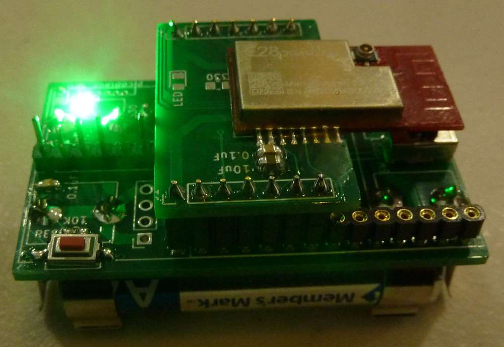
It nicely fits the footprint of two AA batteries. I'll be running some tests soon and hopefully getting definitive answers.By the way, the flashing green LED is being driven by Arduino Pin 20. :smile:
-
Mea Culpa. I found a mistake in my original setup which may explain at least some of the poor performance. I had thought that both my usb-to-serial converters were operating at 3.3v, but I noticed during disassembly that one was operating at 5v instead. Even though I was using pro mini's with 3.3v LDO's on them, it turns out that the 3.3v LDO only functions when the voltage is being fed to the pro mini over the RAW pin (which is never in my setup). Instead, the usb-to-serial converter fed its 5v directly to VCC over the header pin, and from there directly to the radio module. Although I did later do experiments where the entire setup was being run off of 3v of battery only, it may be that the radio module was already damaged by then.
I wouldn't be surprised if others besides just me have fallen into this same trap, as it might be natural to assume that a "3.3v pro mini" regulates all of its voltage sources to be 3.3v. However, such is not the case, as confirmed by checking the schematic.
So, to remove all doubt, I'll use brand new radio modules when testing with this new test setup, which won't be using pro mini's at all this time around. It turns out my barebones atmega328p design works just fine, and this way I have total control over the quality of all the components going into it, including X7R on all the capacitors (whereas who knows exactly what quality of components are used on pro mini's).
-
Here's an end-view of the test platform:
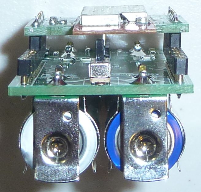
As you can see, I wouldn't want the batteries to be any closer together than they already are, or they would likely short out between them. As it stands, they're firmly in place, so no worries for now. These kinds of placement tolerance issues are hard to vet in advance prior to building a prototype. The keystone datasheet gave no guidance at all on side by side positioning. If I were to do it over, I think I'd give it another millimeter or two of safety factor separation.Of bigger concern is the switch placement. A side mounted switch might be too tight a fit because of the battery connectors. On the other hand, the existing vertical switch can potentially can get in the way of things, so I may try mounting it upside down on the battery side. This would make it less accessible than it currently is, but, at the same time, it wouldn't get bumped by accident either. I reckon that with the aid of an insulated paperclip, or maybe a chop-stick, it should be possible to turn it on-off even in the more cramped position. Probably a more correct solution would be a surface mounted side-switch that's tiny but somehow good enough to carry 600ma+ currents. Finding such a thing may take some searching though, assuming it exists at all.
In a perfect world, the radio module, if it were to use its trace antenna, would be hanging over the end of the base PCB below. Part of the reason it wasn't was out of concern as to whether the breakout board might collide with the switch. Well, with the new switch position, that won't be a worry, so if I create a new version of the breakout board for the radio module, I'd make it so that the radio module has its trace antenna hang out over the end of not just the breakout adapter, but the end of the test platform as well.
I normally use regular headers, but out of an interest in making the whole thing more compact, and for snugger connections, I made a last minute decision to use machine pin headers instead. This was after the board had already been fab'd to use regular headers. If I were to do it over, I would have bigger diameter through-holes drilled into the PCB in order to seat the machine pin female headers properly. I'll do that in the next version I get fab'd, assuming there is a next version.
At the opposite end there's space to add a pico-blade for the FTDI attachment. If that works, then in a future design there will be space for extending a few more pins out from the MCU, making for a more complete universal test platform. For present testing purposes, though, things are good enough as they are.
If anyone reading this has any further thoughts or suggestions, please feel free to jump in and post them. I find it's less fun to do everything single handedly.
-
@NeverDie said in Anyone using/tried the E28-2G4M27S 2.4Ghz LoRa SX1280 27dB module?:
In its favor is that at 40na the sleep current...
I'll order several. Then compare to the TrigBoards. Adafruit's TPL5011 advertises a run current of 20uA. Is that acceptable for you? If so I'll buy several. Couple of limitations for me: 1. Time - I'm about a month out, 2. My Ammeter is a standard DMM from Harbor Freight. The smallest range is 200uA and I've found it very useful. Certainly fine enough to show the 20uA, but inadequate for nanoAmps.
@Larson said in Anyone using/tried the E28-2G4M27S 2.4Ghz LoRa SX1280 27dB module?:
@NeverDie said in Anyone using/tried the E28-2G4M27S 2.4Ghz LoRa SX1280 27dB module?:
In its favor is that at 40na the sleep current...
I'll order several. Then compare to the TrigBoards. Adafruit's TPL5011 advertises a run current of 20uA. Is that acceptable for you? If so I'll buy several. Couple of limitations for me: 1. Time - I'm about a month out, 2. My Ammeter is a standard DMM from Harbor Freight. The smallest range is 200uA and I've found it very useful. Certainly fine enough to show the 20uA, but inadequate for nanoAmps.
I don't see any uCurrent Gold's for sale at the moment, but I did find a clone of it, which has what looks like a nice improvement over the original: you can plug it directly into an oscilloscope via its BNC connector.
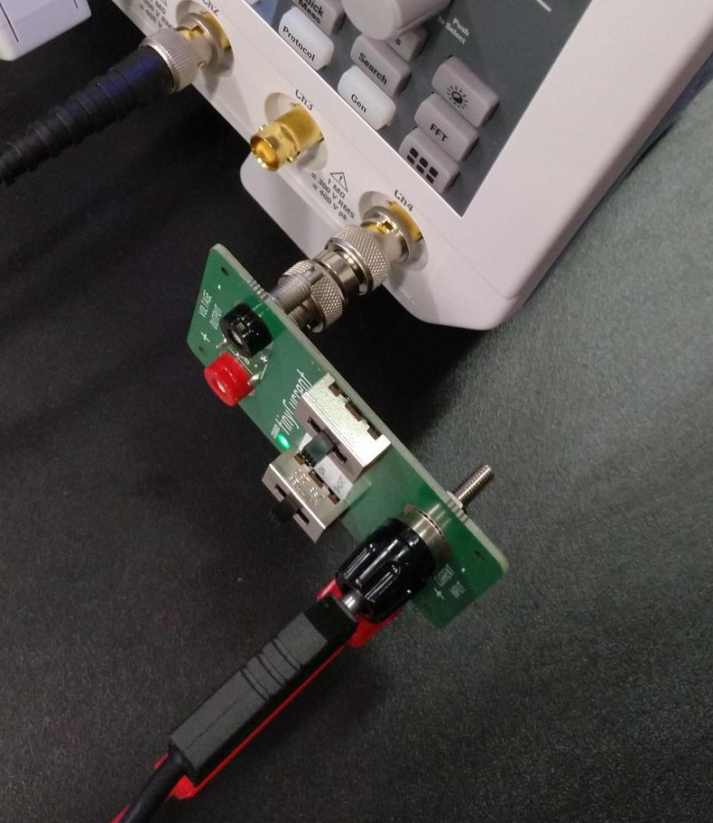
https://www.n-fuse.co/devices/tinyCurrent-precision-low-Current-Measurement-Shunt-and-Amplifier-Device.html
or
https://github.com/nfhw/tinycurrent
as it is open source.I temporarily misplaced my Dave Jones uCurrent Gold that I bought from him directly during his Kickstarter campaign. However, if I can't locate it soon, I may be either buying or making one of these tinyCurrent's to take advantage of the built-in BNC connector.
-
Reporting back: Problem solved!
Using two of the new test nodes, one in transmit and the other in receive, and each using a brand new E28-2G4M27S with just the trace antenna only, and with the default library settings for each, and with the transmit node in a different room with two closed doors in-between (exactly as before, with the initial testing at the start of this thread), I'm now getting the kind of flawless communication that I had expected all along from LoRa on the 2.4Ghz band:
12:23:12 May 18 2022
V1.0

104_LoRa_Receiver_Detailed_Setup Starting

LoRa Device found

SX1280,PACKET_TYPE_LORA,2444999936hz,SF7,BW406250,CR4:5
SX1280,PACKET_TYPE_LORA,Preamble_12,Explicit,PayloadL_255,CRC_ON,IQ_NORMAL,LNAgain_HighSensitivity

Reg    0  1  2  3  4  5  6  7  8  9  A  B  C  D  E  F
0x900  80 FF 77 41 20 FA BC 13 C1 80 00 00 00 00 00 61
0x910  9C 44 00 00 00 19 00 00 00 19 87 65 43 21 7F FF
0x920  FF FF FF 00 70 37 12 50 D0 80 00 C0 5F D2 8F 0A
0x930  00 C0 00 00 00 24 00 21 28 B0 30 0D 01 51 63 0C
0x940  58 0B 32 0A 16 24 6B 96 00 18 00 00 00 00 00 00
0x950  00 00 00 00 00 00 00 00 00 00 00 00 00 00 00 00
0x960  00 00 00 00 00 00 00 00 00 00 FF FF FF FF FF FF
0x970  FF FF FF FF FF FF FF FF FF FF FF FF FF FF FF 04
0x980  00 0B 18 70 00 00 00 4C 00 F0 64 00 00 00 00 00
0x990  00 00 00 00 00 00 00 00 00 00 00 00 00 00 00 00
0x9A0  00 08 EC B8 9D 8A E6 66 04 00 00 00 00 00 00 00
0x9B0  00 08 EC B8 9D 8A E6 66 04 00 00 00 00 00 00 00
0x9C0  00 16 00 3F E8 01 FF FF FF FF 5E 4D 25 10 55 55
0x9D0  55 55 55 55 55 55 55 55 55 55 55 55 55 00 00 00
0x9E0  00 00 00 00 00 00 00 00 00 00 00 00 00 00 00 00
0x9F0  00 00 00 00 00 00 00 00 00 00 00 00 00 00 00 00


Receiver ready - RXBUFFER_SIZE 32

5s  Hello World 1234567890*,CRC,DAAB,RSSI,-54dBm,SNR,10dB,Length,23,Packets,1,Errors,0,IRQreg,8012
9s  Hello World 1234567890*,CRC,DAAB,RSSI,-55dBm,SNR,14dB,Length,23,Packets,2,Errors,0,IRQreg,8012
13s  Hello World 1234567890*,CRC,DAAB,RSSI,-55dBm,SNR,10dB,Length,23,Packets,3,Errors,0,IRQreg,8012
18s  Hello World 1234567890*,CRC,DAAB,RSSI,-58dBm,SNR,13dB,Length,23,Packets,4,Errors,0,IRQreg,8012
22s  Hello World 1234567890*,CRC,DAAB,RSSI,-56dBm,SNR,14dB,Length,23,Packets,5,Errors,0,IRQreg,8012
26s  Hello World 1234567890*,CRC,DAAB,RSSI,-52dBm,SNR,13dB,Length,23,Packets,6,Errors,0,IRQreg,8012
30s  Hello World 1234567890*,CRC,DAAB,RSSI,-53dBm,SNR,9dB,Length,23,Packets,7,Errors,0,IRQreg,8012
34s  Hello World 1234567890*,CRC,DAAB,RSSI,-51dBm,SNR,8dB,Length,23,Packets,8,Errors,0,IRQreg,8012
38s  Hello World 1234567890*,CRC,DAAB,RSSI,-54dBm,SNR,13dB,Length,23,Packets,9,Errors,0,IRQreg,8012
42s  Hello World 1234567890*,CRC,DAAB,RSSI,-52dBm,SNR,14dB,Length,23,Packets,10,Errors,0,IRQreg,8012
46s  Hello World 1234567890*,CRC,DAAB,RSSI,-55dBm,SNR,13dB,Length,23,Packets,11,Errors,0,IRQreg,8012
50s  Hello World 1234567890*,CRC,DAAB,RSSI,-55dBm,SNR,12dB,Length,23,Packets,12,Errors,0,IRQreg,8012
54s  Hello World 1234567890*,CRC,DAAB,RSSI,-56dBm,SNR,9dB,Length,23,Packets,13,Errors,0,IRQreg,8012
58s  Hello World 1234567890*,CRC,DAAB,RSSI,-59dBm,SNR,9dB,Length,23,Packets,14,Errors,0,IRQreg,8012
62s  Hello World 1234567890*,CRC,DAAB,RSSI,-59dBm,SNR,13dB,Length,23,Packets,15,Errors,0,IRQreg,8012
66s  Hello World 1234567890*,CRC,DAAB,RSSI,-61dBm,SNR,13dB,Length,23,Packets,16,Errors,0,IRQreg,8012
70s  Hello World 1234567890*,CRC,DAAB,RSSI,-57dBm,SNR,13dB,Length,23,Packets,17,Errors,0,IRQreg,8012
75s  Hello World 1234567890*,CRC,DAAB,RSSI,-54dBm,SNR,14dB,Length,23,Packets,18,Errors,0,IRQreg,8012
79s  Hello World 1234567890*,CRC,DAAB,RSSI,-55dBm,SNR,14dB,Length,23,Packets,19,Errors,0,IRQreg,8012
83s  Hello World 1234567890*,CRC,DAAB,RSSI,-54dBm,SNR,13dB,Length,23,Packets,20,Errors,0,IRQreg,8012
Notice that now both the RSSI is very good and the SNR is very high as compared to when I was having trouble with the earlier setup.
The E28-2G4M27S is vindicated. Case closed! :smiley:
-
Epilog: I hooked up the old receiver, with its external antenna, to the new mote, and it's not obviously worse for the wear:
12:23:12 May 18 2022
V1.0

104_LoRa_Receiver_Detailed_Setup Starting

LoRa Device found

SX1280,PACKET_TYPE_LORA,2444999936hz,SF7,BW406250,CR4:5
SX1280,PACKET_TYPE_LORA,Preamble_12,Explicit,PayloadL_255,CRC_ON,IQ_NORMAL,LNAgain_HighSensitivity

Reg    0  1  2  3  4  5  6  7  8  9  A  B  C  D  E  F
0x900  80 FF 77 41 20 FA BC 13 C1 80 00 00 00 00 00 61
0x910  9C 44 00 00 00 19 00 00 00 19 87 65 43 21 7F FF
0x920  FF FF FF 00 70 37 12 50 D0 80 00 C0 5F D2 8F 0A
0x930  00 C0 00 00 00 24 00 21 28 B0 30 0D 01 51 63 0C
0x940  58 0B 32 0A 16 24 6B 96 00 18 00 00 00 00 00 00
0x950  00 00 00 00 00 00 00 00 00 00 00 00 00 00 00 00
0x960  00 00 00 00 00 00 00 00 00 00 FF FF FF FF FF FF
0x970  FF FF FF FF FF FF FF FF FF FF FF FF FF FF FF 04
0x980  00 0B 18 70 00 00 00 4C 00 F0 64 00 00 00 00 00
0x990  00 00 00 00 00 00 00 00 00 00 00 00 00 00 00 00
0x9A0  00 08 EC B8 9D 8A E6 66 04 00 00 00 00 00 00 00
0x9B0  00 08 EC B8 9D 8A E6 66 04 00 00 00 00 00 00 00
0x9C0  00 16 00 3F E8 01 FF FF FF FF 5E 4D 25 10 55 55
0x9D0  55 55 55 55 55 55 55 55 55 55 55 55 55 00 00 00
0x9E0  00 00 00 00 00 00 00 00 00 00 00 00 00 00 00 00
0x9F0  00 00 00 00 00 00 00 00 00 00 00 00 00 00 00 00


Receiver ready - RXBUFFER_SIZE 32

4s  Hello World 1234567890*,CRC,DAAB,RSSI,-57dBm,SNR,12dB,Length,23,Packets,1,Errors,0,IRQreg,8012
8s  Hello World 1234567890*,CRC,DAAB,RSSI,-55dBm,SNR,13dB,Length,23,Packets,2,Errors,0,IRQreg,8012
12s  Hello World 1234567890*,CRC,DAAB,RSSI,-57dBm,SNR,13dB,Length,23,Packets,3,Errors,0,IRQreg,8012
16s  Hello World 1234567890*,CRC,DAAB,RSSI,-57dBm,SNR,12dB,Length,23,Packets,4,Errors,0,IRQreg,8012
20s  Hello World 1234567890*,CRC,DAAB,RSSI,-54dBm,SNR,9dB,Length,23,Packets,5,Errors,0,IRQreg,8012
24s  Hello World 1234567890*,CRC,DAAB,RSSI,-52dBm,SNR,3dB,Length,23,Packets,6,Errors,0,IRQreg,8012
29s  Hello World 1234567890*,CRC,DAAB,RSSI,-55dBm,SNR,11dB,Length,23,Packets,7,Errors,0,IRQreg,8012
33s  Hello World 1234567890*,CRC,DAAB,RSSI,-55dBm,SNR,13dB,Length,23,Packets,8,Errors,0,IRQreg,8012
37s  Hello World 1234567890*,CRC,DAAB,RSSI,-50dBm,SNR,12dB,Length,23,Packets,9,Errors,0,IRQreg,8012
41s  Hello World 1234567890*,CRC,DAAB,RSSI,-53dBm,SNR,13dB,Length,23,Packets,10,Errors,0,IRQreg,8012
45s  Hello World 1234567890*,CRC,DAAB,RSSI,-56dBm,SNR,14dB,Length,23,Packets,11,Errors,0,IRQreg,8012
49s  Hello World 1234567890*,CRC,DAAB,RSSI,-53dBm,SNR,8dB,Length,23,Packets,12,Errors,0,IRQreg,8012
53s  Hello World 1234567890*,CRC,DAAB,RSSI,-51dBm,SNR,3dB,Length,23,Packets,13,Errors,0,IRQreg,8012
57s  Hello World 1234567890*,CRC,DAAB,RSSI,-52dBm,SNR,8dB,Length,23,Packets,14,Errors,0,IRQreg,8012
61s  Hello World 1234567890*,CRC,DAAB,RSSI,-52dBm,SNR,12dB,Length,23,Packets,15,Errors,0,IRQreg,8012
65s  Hello World 1234567890*,CRC,DAAB,RSSI,-52dBm,SNR,11dB,Length,23,Packets,16,Errors,0,IRQreg,8012
69s  Hello World 1234567890*,CRC,DAAB,RSSI,-52dBm,SNR,13dB,Length,23,Packets,17,Errors,0,IRQreg,8012
73s  Hello World 1234567890*,CRC,DAAB,RSSI,-50dBm,SNR,13dB,Length,23,Packets,18,Errors,0,IRQreg,8012
77s  Hello World 1234567890*,CRC,DAAB,RSSI,-51dBm,SNR,13dB,Length,23,Packets,19,Errors,0,IRQreg,8012
82s  Hello World 1234567890*,CRC,DAAB,RSSI,-55dBm,SNR,12dB,Length,23,Packets,20,Errors,0,IRQreg,8012
86s  Hello World 1234567890*,CRC,DAAB,RSSI,-56dBm,SNR,7dB,Length,23,Packets,21,Errors,0,IRQreg,8012
90s  Hello World 1234567890*,CRC,DAAB,RSSI,-57dBm,SNR,13dB,Length,23,Packets,22,Errors,0,IRQreg,8012
94s  Hello World 1234567890*,CRC,DAAB,RSSI,-56dBm,SNR,13dB,Length,23,Packets,23,Errors,0,IRQreg,8012
98s  Hello World 1234567890*,CRC,DAAB,RSSI,-48dBm,SNR,6dB,Length,23,Packets,24,Errors,0,IRQreg,8012
One thing I do notice,though, when reviewing the receive packet data, with both the new and old radios are considerable variances in SNR. The 915Mhz adafruit transceivers don't show much variance (see earlier post for the telemetry). I presume, therefore, the larger SNR variances are caused by environmental interference that varies over time in the 2.4Ghz band, or at least the default channel in that band chosen by the library.
The end! :smile:
Hello! It looks like you're interested in this conversation, but you don't have an account yet.
Getting fed up of having to scroll through the same posts each visit? When you register for an account, you'll always come back to exactly where you were before, and choose to be notified of new replies (either via email, or push notification). You'll also be able to save bookmarks and upvote posts to show your appreciation to other community members.
With your input, this post could be even better 💗
Register Login