Anyone using/tried the E28-2G4M27S 2.4Ghz LoRa SX1280 27dB module?


  • @NeverDie said in Anyone using/tried the E28-2G4M27S 2.4Ghz LoRa SX1280 27dB module?:

    ... very much a version 1.0, and it doesn't seem worthy.

    Your humility is profound! But I understand your reluctance as I always find problems with my boards that I later need to hack. Gotta start somewhere, right? Post it please. Next I'll order some SX1280 & 1282 boards. I've got a long way to go.


  • Hero Member

    OK, will do, but for full disclosure, some things I would do differently for version 2.0:

    1. include an ISP header
    2. make it a better fit for machine pins.
    3. Change the routing on one of the power traces so that it doesn't run under the keystone AA battery holder. I found out that solder mask isn't such a good insulator, and I've had a couple of test boards short out there. The workaround was to raise up the keystone, but it's kludgy.
    4. Separate the AA battery holders a bit more so that they don't risk shorting each other out.
    5. Widen the board a bit so that the battery holders don't risk shorting against header pins.
    6. Change the layout so that the radio modules would sit on the end, rather rather than in the center. That way, radio modules with trace antenna could hang over the end of the test setup.
    7. Some changes relating to the silkscreening to make assembly less ambiguous.
    8. Make all of the unused atmega328p pins accessible.

    I guess what I can do is post the version 1.0 boards on openhardware.io as "work in progress" and then upgrade them to version 2.0 when/if that ever happens.


  • @NeverDie said in Anyone using/tried the E28-2G4M27S 2.4Ghz LoRa SX1280 27dB module?:

    I guess what I can do is post the version 1.0 boards on openhardware.io as "work in progress" and then upgrade them to version 2.0 when/if that ever happens.

    I have gathered that openhardware.io can make the effort collaborative. That would be good for me. I've got limited skill in Eagle as that has been my schematic/board platform (plus, of course, board manufactures like OSH Park). Your 8 points are very actionable.


  • @NeverDie Wow, that was fast. I just found it. Thanks. I'm on the bus.


  • Hero Member


  • @NeverDie Thanks again. I've downloaded both and am putting together a BOM to send to DigiKey. Hopefully I'll sneek an order in with my back-ordered PPKII. I'm sure I'll have lots of questions. The Assembly plant I use allows one-side component placement. I'll have to choose one and it will probably be the sole 386p chip. I've never come close to soldering that fine of pitch. Surely it would be a mess.


  • Hero Member

    @Larson You should leave out one 0.1uF capacitor on the atmega328p test platform. If it's installed it won't work. It's the one closest to the LEDs and the picoblade. Including it in the design was an error on my part, but the platform works perfectly fine without it.

    Also you won't need the LED or resistor on the E28-2G4M27S adapter, because you'll have two LEDs to choose from on the atmega328p test platform.


  • Hero Member

    @Larson As to soldering the atmega328p, it's actually easy if you use a lot of rosin flux. Only takes a minute or two to solder by hand and it comes out great. Then clean off the excess flux with IPA. This old school flux works like magic: https://www.amazon.com/gp/product/B008ZIV85A/ref=ppx_yo_dt_b_search_asin_title?ie=UTF8&psc=1


  • @NeverDie I'll give it a go. I've added the flux to my running BOM list. I'm upgrading my alcohol too because my 70% isn't cutting it!


  • @Larson While I definitely agree about the importance of using plenty of flux - it's almost magic - another very important tool is to have plenty of desoldering braid around. It's super cheap, and along with plenty of flux it makes it easy to clean up excess solder on the board or bridging between two pins, or whatever.

    That combination will let you solder all kinds of things that otherwise look very daunting.


  • @NeverDie said in Anyone using/tried the E28-2G4M27S 2.4Ghz LoRa SX1280 27dB module?:

    As you can see, I wouldn't want the batteries to be any closer together than they already are, or they would likely short out between them. As it stands, they're firmly in place, so no worries for now. These kinds of placement tolerance issues are hard to vet in advance prior to building a prototype. The keystone datasheet gave no guidance at all on side by side positioning. If I were to do it over, I think I'd give it another millimeter or two of safety factor separation.

    Add some Kapton tape to the sides of the terminals next to each other to insulate against accidents without making it more cramped.


  • Hero Member

    I just now added schematics to the openhardware.io projects that I posted above.

    I'm trying to post the KiCAD archive, which would be ideal, but the present system extracts the .zip file and only posts a fraction of the files in the KiCAD archive. If I find some another way that works, I'll post it then.


  • Hero Member

    The SX1280 has three possible DIO pins, but, as implied by the library header file, I left two of them disconnected. In hindsight, I wouldn't recommend that. It turns out you can connect any of those DIO pins to any of 16 different SX1280 interrupts using an onchip switching fabric, which I foresee will be quite handy to, for example, rapidly know precisely when a CAD cycle completes or if anything was detected during a CAD cycle. Therefore, until version 2 of the adapter board, I may bodge DIO2 and DIO3 to some of the unused atmega328p interrupt pins as a workable stopgap measure.


  • Hero Member

    OK, I posted the KiCAD 6 archives for both the Ebyte adapter and for the Barebones atmega328p testbed. They appear as a .rar file in the project files on openhardware.io. I'm no longer a bottleneck. Anyone can open them up and pick up exactly where I left off if they want to make changes or fork.

    Inside the .rar file is a zip file. Simply import the project zip file into Kicad, and you're golden.


  • @NeverDie said in Anyone using/tried the E28-2G4M27S 2.4Ghz LoRa SX1280 27dB module?:

    Also, I'm really curious as to how sensitive (or not) the ESP8266 2.4Ghz ESP-NOW communications will be to interference in a home environment that, at least so far, seems to have shredded 2.4Ghz LoRa.

    My ESP-NOW (8266) 2.4 Ghz experience has been pretty uninterrupted that I know of. For about 3 years, I've been monitoring the water pressure of my home system. The sensor/ESP transmitter is at the water heater and the receiver is remote. To give some sense of the density of my WiFi environment: my browser scan detects 7 networks and I live in a medium-density neighborhood (about 4 homes/acre), so it is not too bad. Funny, the recharge curves of the system water pressure, after use, looks just like a capacitor voltage in a RC circuit, only much slower.

    Unlike the low-power theme of this thread, my ESP’s drink as much as they need as they are always on and mains powered.


  • @NeverDie said in Anyone using/tried the E28-2G4M27S 2.4Ghz LoRa SX1280 27dB module?:

    It does a nice job of measuring milliamps. I wouldn't say the PPK2 is good at measuring <1ua currents though, such as sleep currents. If that matters to you, you'll want a Current Ranger, or TinyCurrents or similar.

    Out of gratitude I'd like to buy a TinyCurrent for you. Saw the Donate button on the openhardware.io. Does that go to you?

    The TinyCurrents device would be interesting to own. But if the granularity of the PPKII (still on backorder) is down to 1uA, then anything more exceeds my practical interest. For my hypothetical 2000mAhr battery, a burn rate of 1uA would last 228 years... again, if I did the math right. That exceeds my interest, though it is fun to chase down the details.

    Been re-reading this thread for days. I want to help and hope to, if I can keep up with the blog entries. I've got a shopping list running - some of it already ordered!


  • Hero Member

    @Larson That's very generous of you, but by no means feel obligated. The TinyCurrent-R would be the one to get. Same price as the TinyCurrent, but it has the BNC connector facing the correct direction for connecting directly to an oscilloscope's input terminal.

    I do this stuff because it's both challenging and fun. I enjoy the precision of it. I just keep chipping away at it and eventually make progress. If my posts are of any use to others, then all the better: it all works best when everyone helps everybody else, because collectively we know more than any one of us individually. We've barely scratched the surface of what can be done. Synchronizing clocks among all the different motes and doing time division multiplexing among them would offer ultimate efficiency I think. The technology to do that is already known but the details of how to do it are not on display in a manner that's widely accessible.


  • @NeverDie said in Anyone using/tried the E28-2G4M27S 2.4Ghz LoRa SX1280 27dB module?:

    We've barely scratched the surface of what can be done.

    Openhardware.io gift coming. Please use it to replace your missing uCurrentGold with the proceeds. Someday I’ll contribute my own projects to these splendid forums, I hope.


  • Hero Member

    @Larson Thanks! I purchased it off Ebay, which says I should receive it by July 15,
    TinyCurrent-R.JPG
    though my guess would be probably sooner than that. I'll post a picture after it arrives.
    In combination with an o-scope, It should be good for those occasions where there's a need to capture very fast action in fine detail. 🙂


  • @NeverDie Super. It will be fun to see what you do with it. Glad you have the OC scope to leverage the tool. Cheers.


  • Hero Member

    @Larson You're doing the right thing by getting the PPK2. It will do 99% of what you want, and much more easily than an oscilloscope.

    By the way, in case anyone is interested, there are a couple of reasons why a direct-to-oscilloscope connection beats hooking a typical 1X/10X oscilloscope probe up to, say, a uCurrent Gold or TinyCurrent. The first is that, obviously, there's less noise involved because of the short connection. The second reason is far less obvious, though, which is that the typical 1X/10X oscilloscope probes make for fairly lousy 1X connnections. For measuring small voltages on a 1X connection, you're better off using regular coax or, better still, a direct connection and eliminate the coax altogether. Why? Well, the TL;DR is that oscilloscope probes are optimized for use as 10X (which really meas divide by 10), as explained in the EEVLOG video:
    EEVblog #453 - Mysteries of x1 Oscilloscope Probes Revealed – 29:49
    — EEVblog


    Meanwhile.... I've been trying to get Channel Activity Detection to work on the SX1280, but so far no joy. In some sense it's its own mode, because it "supposedly" times out automatically and returns to Idle mode after a fixed number of symbol periods that's set by SetCadParams. So, I'm puzzled as to what's going on and will have to take a deeper dive to figure this one out. Unfortunately, the library does not support CAD, so there's no working example to start from. There have been some alternative libraries posted on github, so I'll see if they shed any light on how to get CAD working.


  • Hero Member

    Well, this is a good example of how having a PPK2 helps to troubleshoot the CAD problem. We can see from the PPK2 that the CAD actually is activated, once per second, as per my code:
    CAD_activating.png
    So, just knowing that narrows down the problem considerably. The problem now is no longer that but instead why it isn't setting the IRQ flag to indicate that it has finished its detection cycle? The Rx completion flags aren't being set either.


  • Hero Member

    @Larson You'll want to add some jumpers to your BOM if you don't already have them:
    jumpers.JPG
    The above are two motes. The one on the left is used for measurement, and the one on the right isn't.


  • @NeverDie Super, thanks for pointing out the jumpers - very clear to see how they would be used.

    For a long time, I've wanted to make ESP programmer boards that would use springs to temporarily hold the ESP. I actually built one using pogo-pins and a 3-D printed housing pocket. It worked but was fiddly. I may try again on your radio carrier board but differently this time. I’d like to use stiff carbon steel music wire that would be mounted in drilled holes in the existing pads and create new pads on the back-side for mechanical-solder support. Some trace revision would be in order on the back-side, and Captain Tape could cover the new solder pads if needed. Think of it as a bed of nails. Carbon steel music wire is used in springs, I think, and that is what I'd like to use for its stiffness. Perhaps I’ll make the dimension between the rows of holes about 1 mm shy of the distance between the castellated indents. Then to use, push the SX1282 down into the field of springs getting 4 or 5 mm from the carrier board or until the springs start to splay out. If it works, the castellated indent would snuggly fit the wire if I can select the right gauge. One board could then serve different radios of the same class with the same pinouts. The downside may be that I have 16 new unintended antennae. Maybe I could trim these springs shorter after learning how it works.

    The compelling reason for this is to preserve the radio for later permanent installation elsewhere, if needed. There may be some performance degradation as the effective trace length would be longer. I have no idea of the electrical properties of this wire. I'll find out. I’ve got too many ESP’s that are permanently attached to dead testing, or otherwise abandonded, boards. What do you think of the idea?

    Atmega328P selection question: is this linked choice the right pin configuration for the footprint you used? There are so many other choices. Digikey is out of stock, but I'm presuming I'll find them elsewhere.


  • Hero Member

    @Larson AFAIK, any atmega328p with a 32TQFP package should work. Yes, they are in surprisingly short supply right now. Because of that, some people (like Great Scott!) have taken to desoldering them from Pro Mini's, which aren't cheaper but are easier to find. If you go that route, I recommend you buy some ChipQuik to make your desoldering a whole lot easier: https://www.amazon.com/gp/product/B0019UZP7I/ref=ppx_yo_dt_b_search_asin_title?ie=UTF8&psc=1 But that's me. Maybe you have your own preferred method. Whatever works. If you have old projects you no longer use, now is a good time to recycle their parts.


  • Hero Member

    @Larson said in Anyone using/tried the E28-2G4M27S 2.4Ghz LoRa SX1280 27dB module?:

    What do you think of the idea?

    I think it would be easier and less iffy to simply solder it on as per usual and then use ChipQuik if you later wanted to desolder it and move it to another board. But again, that's me. That said, I somewhere have one of those springy jigs that I bought on aliexpress for programming virgin ESP8266's, and it seems to work fine--well, at least for the purpose of installing bootloaders. I never tried to do wifi with them in such a jig, so I don't know what the RF consequencies might be, if any. If you can tolerate some impairment, maybe it's good enough.


  • @NeverDie said in Anyone using/tried the E28-2G4M27S 2.4Ghz LoRa SX1280 27dB module?:

    ... then use ChipQuik if you later wanted to desolder it...

    Okay. One more item for my BOM and skill set. Thanks for the 32TQFP tip also. I do happen to have several Pro Minis and Nanos on hand since I bought them by the dozen - but they are so perfect as they are. Okay, I'll risk one and see how it goes. I am very excited to test the power difference between fuse settings and excluding the external crystal. Andrew Retallack wrote a great series on Beyond the Arduino for power savings and programming in C. I'll have to go back and look but I think it all was based on the external crystal.


  • Hero Member

    @Larson Here's all you need to know in one place on how to get to 100na sleep current on the atmega328p: https://www.gammon.com.au/power He covers all the different methods. TL;DR: burn your fuses to:
    External: 0xFF
    High: 0xDC
    Low: 0xC2
    and then run Sketch J from the Nick Gammon link. That's all there is to it, provided you have an external device/circuit to wake up your atmega328p.


  • @NeverDie said in Anyone using/tried the E28-2G4M27S 2.4Ghz LoRa SX1280 27dB module?:

    Meanwhile.... I've been trying to get Channel Activity Detection to work on the SX1280, but so far no joy.

    Is there a CAD register that can be polled? In the SX1280 datasheet section “11.6.8 SetCAD” there is discussion of a CadDone IRQ. Maybe that can be used outside of the library? Maybe with its own interrupt? It looks to be bit 13 of the IRQ Register per table 11-73. I’ve never played with these radios but have found other devices (simpler devices) to be register friendly. Most of the references to CAD are in section 11. You, no doubt, have already been there. If so, I leave the comment for others.

    [edit: on second read I see you have already been to section 11 with your comment on SetCadParams. Hmmm... wish I knew more. I'll play with it when I get set-up.]


  • Hero Member

    @Larson said in Anyone using/tried the E28-2G4M27S 2.4Ghz LoRa SX1280 27dB module?:

    @NeverDie said in Anyone using/tried the E28-2G4M27S 2.4Ghz LoRa SX1280 27dB module?:

    Meanwhile.... I've been trying to get Channel Activity Detection to work on the SX1280, but so far no joy.

    Is there a CAD register that can be polled? In the SX1280 datasheet section “11.6.8 SetCAD” there is discussion of a CadDone IRQ. Maybe that can be used outside of the library? Maybe with its own interrupt? It looks to be bit 13 of the IRQ Register per table 11-73. I’ve never played with these radios but have found other devices (simpler devices) to be register friendly. Most of the references to CAD are in section 11. You, no doubt, have already been there. If so, I leave the comment for others.

    [edit: on second read I see you have already been to section 11 with your comment on SetCadParams. Hmmm... wish I knew more. I'll play with it when I get set-up.]

    Yeah, I'd say the Semtech SX1280 architecture is quite different than a lot of previous Semtech chips, which, you're right, in prior times were very register oriented. There still are some registers, but for SX1280 Semtech adopted a less transparent op-code architecture where you can issue commands--but in some cases there's no way to verify whether the command "sticks" like there is with a register oriented architecture, where you can always read-back the register to confirm that what you think you wrote to a register was actually written exactly as you wrote it. This is making troubleshooting relatively hard, because the chip has some internal states that you can no longer read like you could with a more register oriented architecture. Instead, you send an op-code over SPI, and maybe some parameters to go with it (the type and number of which can vary), which you "hope" works. I don't like it at all, because, among other things, it assumes that the documentation is 100% complete and flawless--and documentation never is. In particular, the SX1280 datasheet never gives the exact protocol for launching CAD, and whatever that protocol is, I seemingly haven't found it yet, despite testing numerous possibilities--though I may have gotten close. And in a system with more than one SPI device, what happens if there's some conflict in your SPI communication? How do you ever unravel what it is if there's no way to verify? Seems like heartache waiting to happen. I don't understand why the opcode system is thought to be better. Anyone know?

    Anyhow, Stuart's Projects never implemented CAD, and internally I'm finding it makes, IMHO, some seemingly improper assumptions about which IRQ's are assigned to which DIO's in how it operates. That makes it brittle. That's something one just can't know when looking purely at a library's veneer. Anyway, the good news is that late last night I found a different, more general library which claims to have a working SX1280 CAD example, so I'll be giving it a test drive soon. https://github.com/jgromes/RadioLib It's not radiohead, but it's a similarly ambitious library project that spans multiple different kinds of radios and multiple different kinds of MCUs. If the CAD demo code works, then I'll adopt the new library and drop Stuart's Projects. If nothing else, I admire the authors ambition to be the one library to rule them all. As I hate changing libraries, I truly hope this is "the One" library that can do that. 🙂


  • Hero Member

    Well, the Radiolib CAD example compiles and runs, and it nominally looks like it should:
    radiolib_cad.png

    I just need to introduce a separate LoRa transmitter to the vicinity to confirm that the detection actually works. I'm guessing the LoRa parameters have to be an exact match (SF at minimum and maybe other parameters as well). Then, sending a long enough string--and maybe reducing delays in the CAD detector loop--should lead to a detection.

    [Edit: Yup, I tried running the generic SX1280 Radiolib transmit example, with delay removed, and the CAD detector easily detects it. It works! 🙂 🙂 🙂 ]


  • Hero Member

    Since the Barebones v001 is, after all, a test platform, I'm going to assemble a mote and SX1280 adapter that use Dupont headers. The reason is that the 8 sense pins on the PPK2 work with Dupont wires, and I don't see an easy way to make those work with machine pin headers. No change in the PCBs is required. @Larson You may want to assemble your motes this way from the get-go.

    By the way, can anyone here recommend where I can buy "good" Dupont wiring and connectors? If I buy from China, I seem to often get very loose-goosey connections.

    P.S. I could be wrong, but the RadioHead library seems to have stopped progressing. None of the newer LoRa chips are in any of its examples. Too bad, as it was a very progressive library in its day. That leaves RadioLib as the library to rule them all. However, it has a very different overarching paradigm than, say, StuartsLibrary, which was easier to grasp.


  • @NeverDie said in Anyone using/tried the E28-2G4M27S 2.4Ghz LoRa SX1280 27dB module?:

    Dupont headers

    My plan is to use female headers on the Barebones board, then to use doubled long-legged male headers on the SX1280 adapter board like these from Digikey. It all stacks together and bed of nails will stick out the top of it all. That way the PPK2 Dupont females can nicely plug onto the any of the protruding males in the stack that I select to use as a signal or interrupt. Again, I risk a bed of 16 inadvertent antennae with all that metal in the air. I can always snip-off the pins I don’t use. PPK2 is expected on Monday!

    I spent the day shopping for parts at Aliexpress, Digikey, and Amazon. I found some 328P's at Aliexpress. Could be some time for the Aliexpress parts (SX1280 module). In the meantime I'll be learning KiCAD. I'm hoping that Eagle and KiCAD might allow file swapping as Eagle is familiar ground for me. Or ... I could just take the easy path and go directly to OSHPark since you have made it so easy.


  • Hero Member

    @Larson said in Anyone using/tried the E28-2G4M27S 2.4Ghz LoRa SX1280 27dB module?:

    @NeverDie said in Anyone using/tried the E28-2G4M27S 2.4Ghz LoRa SX1280 27dB module?:

    Dupont headers

    My plan is to use female headers on the Barebones board, then to use doubled long-legged male headers on the SX1280 adapter board like these from Digikey. It all stacks together and bed of nails will stick out the top of it all. That way the PPK2 Dupont females can nicely plug onto the any of the protruding males in the stack that I select to use as a signal or interrupt. Again, I risk a bed of 16 inadvertent antennae with all that metal in the air. I can always snip-off the pins I don’t use. PPK2 is expected on Monday!

    Somehow I had gotten it in my head to use extra long female headers (such as these, https://www.amazon.com/gp/product/B071GTP5V6/ref=ppx_od_dt_b_asin_title_s00?ie=UTF8&psc=1, or similar) on the adapter board and then regular female headers on the basic atmega328p PCB. Maybe it's a wash?


  • Hero Member

    @Larson KiCAD 6 allows for importing Eagle projects right from within KiCAD 6 itself. Not sure what options, if any, might exist for exporting to Eagle. I think you'll like KiCAD 6. It's pretty easy to pick it up--much easier than earlier versions. I previously used Diptrace, because it was so easy, but I've since moved completely over to KiCAD 6 because it's just as easy, but also more widely supported in terms of parts libraries. Also, unlike Diptrace, it makes sharing projects a snap--just create an archive (literally a one menu click operation), and share the resulting zip file.


  • @NeverDie said in Anyone using/tried the E28-2G4M27S 2.4Ghz LoRa SX1280 27dB module?:

    Somehow I had gotten it in my head...

    So many ways to cook an egg. The pleasure is in eating it. I'll take a picture of my wedding-cake-of-a-board stack when I finish. It may not be until July at my pace.

    Re KiCAD: I look forward to trying. Recently JLCPCB made me learn EasyEDA and it really went well. Learning Eagle took me a week the first time, 2 days the second time, and still... I have to retrain. That is the joy of it all, right?


  • Hero Member

    By the way, I've recently been reporting some other progress on the SX1280 on my radio-comparison thread: https://forum.mysensors.org/topic/11954/most-reliable-best-radio/27?_=1654402718278 For things that are both battery operated and subject to remote control, the importance of being able to quickly wake them up at a moments notice, but with minimal ongoing energy drain, is an important topic. Examples: key finder fobs, remotely opening/closing blinds at the push of a button, etc.


  • @NeverDie said in Anyone using/tried the E28-2G4M27S 2.4Ghz LoRa SX1280 27dB module?:

    reporting some other progress

    Yes, I have been there, though not lately. Thanks for the reminder. What great information and exchanges.


  • Hero Member

    From the perspective of having some kind of general purpose platform--not just for testing but as a "go-to" for general use--it would be nice to have some kind of project box or enclosure of some kind for it. That would prevent things in the environment from pushing up against the electronics/PCB and possibly shorting it out. Anyone have any ideas on what form that should take? There's always the option of custom 3D printing something, but if there were a box of the right size already out there, that would be much easier. In that case one could customize the PCB to fit it precisely instead of 3D printing a box to precisely fit the PCB. Having a nice enclosure is one of the things that typically separates store-bought sensors from hobbyist projects.

    By the way, the SHT45 TH sensor that I mentioned in the OP is now available on mouser. Unfortunately, it seems they nearly doubled their asking price over what they had earlier projected, so that's a bit of a disappointment. I guess these days a lot of chips are marked up due to the widespread shortages going on.... The chip itself is quite small, but it only has four landing pads, so I'm thinking that hand soldering it should be manageable. A simple adapter board, like this one for the SHT40, would allow it to easily fit the platform:
    sht40.JPG
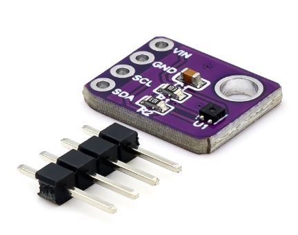
    because the platform's pinout already anticipates adding up to two I2C devices without any fuss, like thus:
    TH_addon_1.JPG
    TH_addon_2.JPG
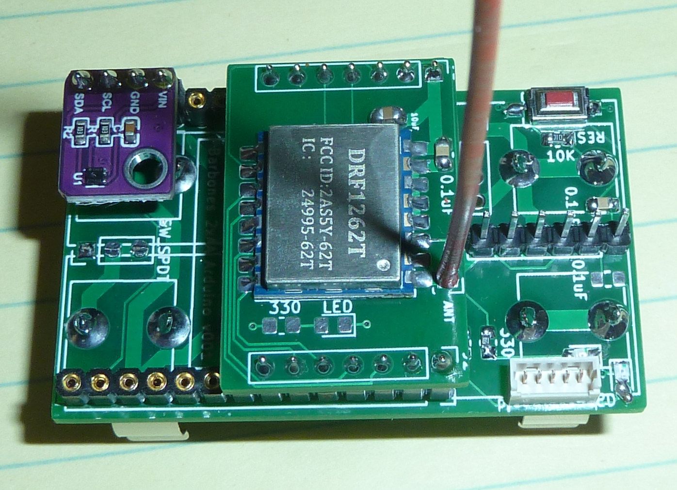
    FYI, I updated the project page with a bunch of photos.


  • @NeverDie said in Anyone using/tried the E28-2G4M27S 2.4Ghz LoRa SX1280 27dB module?:

    Anyone have any ideas on what form that should take?

    Looks great! I’ve had good luck at Aliexpress with a variety of boxes like these. Some boxes have mounting lugs on the bottom. Your board has no space for mounting holes. I could help with the redesign??? Then I'd use stand-offs to get to the lugs and suspend the batteries in the air off the bottom. The antenna could be curled inside the box, but I've found that to have a negative impact (probably the polairity thing.

    [Edit: Forgot to say that I've thrown in the little bags of desiccants for good measure. I find them in my pill bottles.]


  • @NeverDie I've made progress. I've ordered these items (mostly radios):
    SX1278
    SX1280
    nrf24012mg E01's
    nrf2401+
    Bunch of antenna parts
    TPL5110
    Atmega328's
    I cannot find any SX1262's and after your other post ("Best") I see that this is the darling to have. Any idea of where to find some?

    Fun to see the photos of the current meter in sleep action on your other post.

    One addition I would like to make to your boards is a GPS chip. The idea would be to walk about in a field and collect RSSI and SNR data. Combining these elements would give a pretty good picture of signal vs the 2-dimensions of GPS data - for each radio and different modulations, spreading factors... Trouble here is that there are too many parameters to play with. I see Excel graphics coming into play. I have no experience with GPS, although I own a few of the chips.


  • Hero Member

    The ones I've tried so far are these: https://www.ebay.com/itm/202574135410?hash=item2f2a5c0072:g:H9EAAOSwLuldcige Maybe it was luck, but the seller delivered fairly quickly, and they were very well packed. They allegedly contain TCXO's, so that presumably makes them better than those moules which don't have TCXO's.

    I just today received these Ra-01SH, but haven't tried them yet: https://www.aliexpress.com/item/2255800961841511.html?spm=a2g0o.order_list.0.0.20411802pmZPEx&gatewayAdapt=4itemAdapt
    I have custom adapter boards for them though. At the time I ordered them in April they were just $3.31 each, but now the same seller is asking $4.24. Delivery time was pretty long (longer than originally promised). So, you may want to shop around. If this is the new market rate, then I would go for the Dorji boards instead, because for the money you at least get TCXO's with the Dorji's, and they allegedly passed FCC. On the other hand, I've had good luck with Ai-Thinker in the past.

    There are some other brands out there as well, but these are the only two for which I made adapter boards.


  • Hero Member

    @Larson I don't know how well GPS location works indoors, but it if somehow does that would be interesting. If it has gotten small enough and cheap enough and low power enough, it would be interesting for clock synchronization as well, though there are other ways of doing that.


  • Hero Member

    Wow, I just checked, and GPS receivers have really gotten small, especially as compared to 5 years ago. Just 7mmx7mm in size: https://www.mouser.com/ProductDetail/Quectel/LG77LIAMD?qs=zW32dvEIR3sKRLNP92tehQ%3D%3D

    That's way smaller than the old Adafruit one that I have: https://www.adafruit.com/product/5440
    which is gigantic.


  • @NeverDie Thanks, once again. Done and purchased (4 1262's, and 2 1276's (ra-01SH)). I don't know why google and I couldn't find the1262's, nor Digikey, nor Ali, nor Amazon. So I'm on the slow road. I don't expect you to wait for me but your records in this forum are a standing education for all that follow. I'm sure I'll have observations/questions if you are still there.

    Per my GPS thinking: I was thinking outdoors in an open field. I know your objective was through a reinforced footing, across the house, and up a floor. For that environment I would map the house into a grid with surveyor's cord and walk a defined pattern, clicking a button for every grid point I cross. Then I'd go to the yard with the same idea. My wife tells me I'm hard to live with... imagine that.


  • Hero Member

    @Larson According to AI-thinker, the Ra-01SH is an SX1262, not a 1276. The SX1262's are more capable, whereas the 1276's are older generation. https://docs.ai-thinker.com/_media/lora/docs/ra-01sh_specification.pdf AFAIK, the two adafruit modules I got for trial purposes were SX1276's.

    Since you'll be trying more than just the Ebyte module, let me know if you'd like me to post the other adapter boards also (e.g. for the Dorji SX1262, the Ra-01SH, and the nRF24L01). The work is already done.


  • @NeverDie said in Anyone using/tried the E28-2G4M27S 2.4Ghz LoRa SX1280 27dB module?:

    That's way smaller than the old Adafruit one that I have: https://www.adafruit.com/product/5440
    which is gigantic.

    At some point, like this, bigger is better for me. Imagine the size of the GPS in modern phones. I prefer the Adafruit type that has breakout pins and 'hold-my-hand' tutorials. We live in a golden age. I have to go find my GPS boards that i think I have. It has been some time and I've always wanted some purpose. This may be the time.


  • Hero Member

    Definitely agree that it's the tutorials that make the adafruit hardware worthwhile, typically much more so than the hardware itself.


  • @NeverDie said in Anyone using/tried the E28-2G4M27S 2.4Ghz LoRa SX1280 27dB module?:

    let me know if you'd like me to post the other adapter boards

    The other adapter boards would be great... but I thought I'd earn my way into it by working with what you have already posted for the SX1280. To date I've been collecting pinouts to study the patterns so I could understand the template(s). What ever you post is a gift and I thank you. I'm sure that others to come will also enjoy. You have built quite a platform and I'm inspired.


  • @NeverDie said in Anyone using/tried the E28-2G4M27S 2.4Ghz LoRa SX1280 27dB module?:

    According to AI-thinker, the Ra-01SH is an SX1262, not a 1276.

    As I'm shoping around I found the Ra-01 Lora, but it was assocaited with the 1276 per this link you offered: https://www.aliexpress.com/item/2255800961841511.html?spm=a2g0o.order_list.0.0.20411802pmZPEx&gatewayAdapt=4itemAdapt&aff_fcid=d9908c021fe34eeeb0ea05b879ca4432-1654498510220-06752-_uYd1nh&aff_fsk=_uYd1nh&aff_platform=api-new-link-generate&sk=_uYd1nh&aff_trace_key=d9908c021fe34eeeb0ea05b879ca4432-1654498510220-06752-_uYd1nh&terminal_id=afb1662bfbca4bd68d5ee03a630ea8c7&afSmartRedirect=y.

    Given that I haven't studied the datasheets, I don't exactly know the shape-shifting ability of one chip to act as another. Not sure where to go with this one - but I'll know more when they arrive. I'll work on it in the AM when I'm fresher.


  • Hero Member

    @Larson When you hover over the different modules on that webpage, it will tell you the name of the model. They're all different.


  • @NeverDie Groovy. And good night. So much to learn.


  • @NeverDie said in Anyone using/tried the E28-2G4M27S 2.4Ghz LoRa SX1280 27dB module?:

    Anyone have any ideas on what form that should take?

    Second effort: This link shows a type of box with mounting points on the bottom. It would be nice if there were a PCB footprint for the holes, but I could find none. Using a paper rubbing and a set of calipers one can create their own footprint and build the PCB to that dimension. For any hard wires that must be passed through the box, I've been using cable glands like these for a waterproof enclosure. See the Cave Pearl Project for a different deep-sea approach,


  • Hero Member

    I posted the rest of the radio module adapters to openhardware.io.


  • @Larson said in Anyone using/tried the E28-2G4M27S 2.4Ghz LoRa SX1280 27dB module?:

    Not sure where to go with this one - but I'll know more when they arrive. I'll work on it in the AM when I'm fresher.

    How confusing. On the EC-Buying Ali Store they show associations of the RA-01 with SX1262, SX1272, and SX1278 in titles on separate pages. Each of these pages show a variations on the RA-01 title (S, H, SH, SC...). I'll take your word for it. So it looks like all 6 radios I ordered last night are SX1262's then.

    Found my GPS! It is really big & heavy too.


  • @NeverDie said in Anyone using/tried the E28-2G4M27S 2.4Ghz LoRa SX1280 27dB module?:

    I posted the rest of the radio module adapters to openhardware.io.

    Wow. Thanks. I'll be sure to report back on what I come-up with.


  • @NeverDie Been gone today so unable to play. Thanks again for generously sharing your work. I'm just now starting to look at the files: so cool! I like your broad power traces and skinny signal traces. And the pads on the radio chips are really tiny. I suspect these design choices are not accidental.

    Look out OSH Park, here I come.


  • Hero Member

    @Larson One thing Diptrace had that KiCAD lacks is a built-in auto-router. As a result, I manually routed as fast as I could so that I could place the order without delay. I've heard there are auxillary auto-routers. If any of them are any good, it would be a nice tool to have. Drafting the schematics goes pretty fast; it's the routing that soaks up the bulk of the time.


  • @NeverDie In Eagle, I found that the auto-router gives no joy. Seems to be that the art of the board is best done manually.

    I'm just now looking at one board (DRF1262TG) in OSH Park that I've uploades. The view is much better than looking at the *.svg files. The radio pads look like even I can hit them with solder. Gave me a better feel. Golden age... thank you again.


  • Hero Member

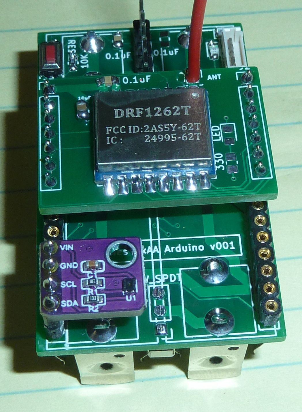
    @Larson This time using female headers, I built a new platform and Ebyte adapter, as discussed earlier.
    ppk2_rigging.JPG
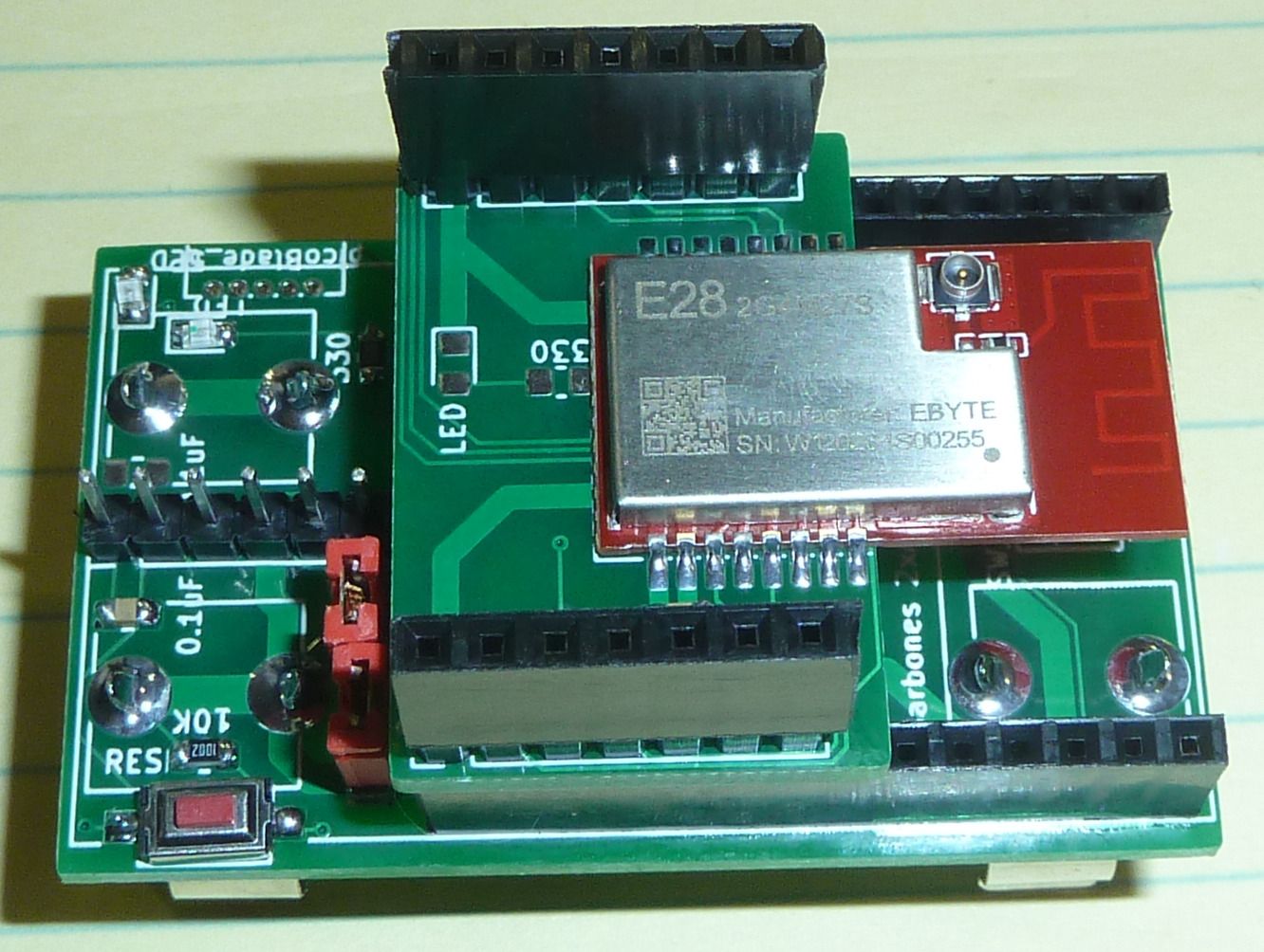
    I expect this version will be fully Dupont compatible with the PPK2 probe pins. Unfortunately, if you look carefully you'll see that the adapter PCB covers up the nearest header pin hole beneath it on either side of the board. Ooops! I'll have to fix that in the next revision of the adapter board. For now it's no biggy, though: it's PPK2 access to the pins on the adapter board that matter most, and those are now fully exposed for probing.


  • Hero Member

    @Larson said in Anyone using/tried the E28-2G4M27S 2.4Ghz LoRa SX1280 27dB module?:

    @NeverDie The radio pads look like even I can hit them with solder.

    When I'm designing module PCB landing pads, I almost always make them longer than what the datasheet recommends to make orienting the module and soldering it in place easier. In contrast, the datasheet always specifies the absolute minimum.


  • @NeverDie said in Anyone using/tried the E28-2G4M27S 2.4Ghz LoRa SX1280 27dB module?:

    if you look carefully you'll see that the adapter PCB covers up the nearest header pin hole beneath it on either side of the board.

    Yea, but a Dremmel snip job would have those two pins accessible in a flash! In my hackish world, there has to be three errors to warrant redsign... unless it is an unrecoverable error, of course!


  • Hero Member

    @Larson Are you able to get input to work on any of the 8 PPK2 sense pins? Mine isn't responding at all. They all read high, even if I connect one of them directly to PPK2 ground. Matter of fact, I'm not even getting any voltage out of the logic analyzer's VCC pin. If yours is working, then maybe mine is defective or something.

    Where were you able to get yours from? The place I ordered from no longer has them in stock. I'm debating whether to backorder from mouser. Argh. I hope it doesn't come to that. Weird that the current portion of the PPK2 is working, but not the logic analyzer part.

    I've submitted a ticket to Nordic and contacted the seller, but of course nothing happens very quickly and I probably won't hear from them anytime soon.


  • @NeverDie The PPKII arrived yesterday! I've only cracked it out of the box and haven't tried. I'll do so next. Been spending my time in KiCAD tutorials, looking at your boards and taking care of family! I'm like an excited dog in a 3-D field of fire-hydrants! Never enough time for a slow-reader like me.

    My PPKII source: DigiKey 5/24/22 order. Here is the scoop off the invoice (most importantly the part no): PART: 1490-NRF-PPK2-ND MFG : NORDIC SEMICONDUCTOR ASA / NRF-PPK2 DESC: POWER PROFILER KIT 92.50000 92.50 COO : POLAND ECCN: EAR99 HTSUS: 8543.70.9860 ROHS3 COMP REACH UNAFFECTED 25-JUN-2020
    It sure came fast for being back-ordered.

    I also received a bunch of other solder stuff you recommended and a solder plate. Again, too excited, but life is getting in the way. Radio’s are on their way, mostly from AliExpress. Too bad they fractionalize one order; now I’ve got about a dozen different order-tracking email threads.

    PPKII test: I’m planning on a vanilla ProMini with and without the conventional crystal – per your tutorial. I will throw in a signal cue on a pin to test the logic analyzer thing. Will that be sufficient to test? Hope to report by the end of the week if the distractions end.

    Then I’d like to try the PPKII on the Darrah Trig Board; I know, I can’t read the deep sleep with a PPK, but it will be a good first-try for me with the Trig Board.


  • @NeverDie said in Anyone using/tried the E28-2G4M27S 2.4Ghz LoRa SX1280 27dB module?:

    Matter of fact, I'm not even getting any voltage out of the logic analyzer's VCC pin.

    Maybe a stupid question... but are you powering from the PPKII source, or the device-under-test battery? Does it matter? I know nothing about the PPKII, yet. But I have read that the burden voltage is an issue even on the PPKII. I have no idea if the LA is complicated by this.


  • Hero Member

    @Larson said in Anyone using/tried the E28-2G4M27S 2.4Ghz LoRa SX1280 27dB module?:

    @NeverDie said in Anyone using/tried the E28-2G4M27S 2.4Ghz LoRa SX1280 27dB module?:

    Matter of fact, I'm not even getting any voltage out of the logic analyzer's VCC pin.

    Maybe a stupid question... but are you powering from the PPKII source, or the device-under-test battery? Does it matter? I know nothing about the PPKII, yet. But I have read that the burden voltage is an issue even on the PPKII. I have no idea if the LA is complicated by this.

    I've tried it both ways, and I'm just not getting anything out of the logic port.


  • Hero Member

    @Larson said in Anyone using/tried the E28-2G4M27S 2.4Ghz LoRa SX1280 27dB module?:

    Will that be sufficient to test? Hope to report by the end of the week if the distractions end.

    I imagine so.


  • @NeverDie said in Anyone using/tried the E28-2G4M27S 2.4Ghz LoRa SX1280 27dB module?:

    I know nothing about the PPKII, yet. But I have read that the burden voltage is an issue even on the PPKII.

    And, I think I learned about the PPKII burden voltage from you!


  • Hero Member

    @Larson said in Anyone using/tried the E28-2G4M27S 2.4Ghz LoRa SX1280 27dB module?:

    @NeverDie said in Anyone using/tried the E28-2G4M27S 2.4Ghz LoRa SX1280 27dB module?:

    I know nothing about the PPKII, yet. But I have read that the burden voltage is an issue even on the PPKII.

    And, I think I learned about the PPKII burden voltage from you!

    The PPK2 seems to work fine when powering the circuit whose current it is measuring, but if externally powered then, yes, for some reason it seems to choke the DUT.

    Because the PPK2 is out-of-stock everywhere, I decided that rather than be held prisoner by whatever lengthy return/warranty cycle for my PPK2 is likely to be, I would upgrade my o-scope to one that can do integrations and sell my old scope, which can't do integrations. New scope should arrive on Thursday.

    If you're wondering how that works, this explains it:
    EEVblog #662- How & Why to use Integration on an Oscilloscope – 19:53
    — EEVblog

    As you can see, the UI is nowhere near as nice as the PPK2 for measuring current consumption. Perhaps offsetting that somewhat is that the o-scopes resolution should be better: the PPK2 has 100,000 samples per second, whereas these days a decent entry-level o-scope will commonly have 1 giga-samples/second.

    I still like the PPK2, and I look forward to exchanging the one I have for one that works.


  • @NeverDie I have no experience with an O. Scope, or a PPKII. I presumed the OS gives one much more dimension of analysis. But as indicated my Harbor Freights DMM delivers nearly everything I need. Sure is fun to listen to Dave Jones. The man is a source of knowledge and excitement spiced with humor.


  • Hero Member

    Good news! My PPK2 works after all. After experimenting, I determined that '"VCC" on the logic port is not a voltage source, as its name would imply. Instead, it is a voltage sense pin. So.... the way to make the logic port work is to wire the logic port VCC to the VOUT (or to whatever VCC that's powering your project). After doing so, D0 through D7 work as you would expect.

    Also worthy of note: there evidently are no internal pull-up or pull-down resistors on any of the D0-D7 logic port sense pins. So, if, for example, you give D0 a high pulse and then disconnect from it, D0 will tend to stay high until it receive a low pulse.

    Happy I don't need to return/exchange the PPK2 after all. 🙂


  • Hero Member

    @Larson Something I only just recently started using in the last couple of days that you may like: 0.4mm diameter Kester Rosin solder. It's ridiculously thin, but for soldering radio modules onto boards, I'm finding that I can more precisely put just enough solder exactly where I want it without having to apply solder flux to the module afterward.


  • @NeverDie said in Anyone using/tried the E28-2G4M27S 2.4Ghz LoRa SX1280 27dB module?:

    Glad to hear you solved it. I was hoping to help you, for a change. You are too fast for me. I just got home from a grueling day.

    So, if, for example, you give D0 a high pulse and then disconnect from it, D0 will tend to stay high until it receive a low pulse.

    By 'disconnect' do you mean sleeping? It sounds like Pull-Up/Down on the DUT pin would solve it. Ohhh, I'm thinking that disconnect means when the MCU disengages the PPKII. Or perhaps VCC pin is at play. I know so little of the PPKII, but I would imagine it couldn't have any Pull-Up/Down assignments or it would be fighting the DUT Pull direction. The result of double pulls would be a voltage divider and give some misleading indications.


  • Hero Member

    @Larson said in Anyone using/tried the E28-2G4M27S 2.4Ghz LoRa SX1280 27dB module?:

    @NeverDie said in Anyone using/tried the E28-2G4M27S 2.4Ghz LoRa SX1280 27dB module?:

    Glad to hear you solved it. I was hoping to help you, for a change. You are too fast for me. I just got home from a grueling day.

    So, if, for example, you give D0 a high pulse and then disconnect from it, D0 will tend to stay high until it receive a low pulse.

    By 'disconnect' do you mean sleeping? It sounds like Pull-Up/Down on the DUT pin would solve it. Ohhh, I'm thinking that disconnect means when the MCU disengages the PPKII. Or perhaps VCC pin is at play. I know so little of the PPKII, but I would imagine it couldn't have any Pull-Up/Down assignments or it would be fighting the DUT Pull direction. The result of double pulls would be a voltage divider and give some misleading indications.

    By disconnect I just mean, for example, taking a wire that's connected to D0 and touching it to GND and then pulling the wire away so that it's no longer touching GND. It's not something you would do "in real life," but I was doing it just to confirm that the PPK2 was working.


  • @NeverDie said in Anyone using/tried the E28-2G4M27S 2.4Ghz LoRa SX1280 27dB module?:

    0.4mm diameter Kester Rosin solder.

    I'll put it on my list. After the Male/Female antennae discussion above, I'm sure I got my order wrong - so I'll have a new running list shortly when everything arrives. I checked my solder with a caliper since the dimensions are listed in Chinese: it is 0.6 mm so I'm not far away. I do like the feel the smaller diameter has in comparison to my larger solder so I'm sure 0.4 mm will even be better.


  • Hero Member

    @Larson said in Anyone using/tried the E28-2G4M27S 2.4Ghz LoRa SX1280 27dB module?:

    @NeverDie said in Anyone using/tried the E28-2G4M27S 2.4Ghz LoRa SX1280 27dB module?:

    0.4mm diameter Kester Rosin solder.

    I'll put it on my list. After the Male/Female antennae discussion above, I'm sure I got my order wrong - so I'll have a new running list shortly when everything arrives. I checked my solder with a caliper since the dimensions are listed in Chinese: it is 0.6 mm so I'm not far away. I do like the feel the smaller diameter has in comparison to my larger solder so I'm sure 0.4 mm will even be better.

    Yeah, I was using 0.635mm MG Chemicals solder previously, but I found I had to drown the radio modules in rosin flux afterward to eliminate solder bridges, etc. Perhaps part of the difference may be that Kester uses a different formulation for its in-line flux than MG Chemicals? I suppose that could also have something to do with it. So, maybe it's not entirely diameter, but having now worked with the two different diameters, my gut intuition is that the smaller diameter is helping.

    Anyone else reading this having any opinions on the matter that they are willing to share?


  • @Larson said in Anyone using/tried the E28-2G4M27S 2.4Ghz LoRa SX1280 27dB module?:

    I checked my solder with a caliper since the dimensions are listed in Chinese: it is 0.6 mm so I'm not far away.

    Ha, I just did the simple math. Since the cross-sectional area is function of the squared radius, 0.4 is vastly different (better?) than the 0.6 mm. The 0.4 mm will feed 2.25 times as fast as the 0.6 mm for the same volume - maybe even more if there is a higher evaporative flux component. That is a big difference.


  • @NeverDie said in Anyone using/tried the E28-2G4M27S 2.4Ghz LoRa SX1280 27dB module?:

    Anyone else reading this having any opinions on the matter that they are willing to share?

    I'm sure there are. Initially, I was not only occasional but also reluctant to comment due to my lack of credible contribution. You helped me overcome that. This thread will be a resource for a multitude of others that will be too late for contemporary comment. Keep on going, man.

    Today's achievement for me: PPK2 software is loaded (not that simple) and it is funcitoning. Super cool metrics. I'll shortly post my crystal/non-crystal measurements for my own enjoyment.


  • @NeverDie said in Anyone using/tried the E28-2G4M27S 2.4Ghz LoRa SX1280 27dB module?:

    @Larson said in Anyone using/tried the E28-2G4M27S 2.4Ghz LoRa SX1280 27dB module?:

    @NeverDie said in Anyone using/tried the E28-2G4M27S 2.4Ghz LoRa SX1280 27dB module?:

    0.4mm diameter Kester Rosin solder.

    I'll put it on my list. After the Male/Female antennae discussion above, I'm sure I got my order wrong - so I'll have a new running list shortly when everything arrives. I checked my solder with a caliper since the dimensions are listed in Chinese: it is 0.6 mm so I'm not far away. I do like the feel the smaller diameter has in comparison to my larger solder so I'm sure 0.4 mm will even be better.

    Yeah, I was using 0.635mm MG Chemicals solder previously, but I found I had to drown the radio modules in rosin flux afterward to eliminate solder bridges, etc. Perhaps part of the difference may be that Kester uses a different formulation for its in-line flux than MG Chemicals? I suppose that could also have something to do with it. So, maybe it's not entirely diameter, but having now worked with the two different diameters, my gut intuition is that the smaller diameter is helping.

    Anyone else reading this having any opinions on the matter that they are willing to share?

    I swear by the stuff in the picture below. It melts at a lower temperature(179 C) so, as an amateur, I feel safer keeping my iron at a lower temp and in place a little longer when I am working with IC's. I like that it's thin too as it is easier to control how much you apply. I have no issues with it, it flows well and doesn't create bridges (unless I use too much).

    PXL_20220609_213636256.jpg


  • Hero Member

    @alphaHotel Thanks for the tip! I added it to my mouser shopping basket.

    Like Dave from EEVblog I tend to run my soldering pencil hotter than I should but work quickly to compensate, so maybe with this Chipquik solder I can dial it down. For sure the Chipquik desoldering solder works extremely well.


  • @alphaHotel & @NeverDie: My ChipQuik kit arrived as did the SRA flux. Look forward to working with it. I find the "No-Clean" claim concerning but I am armed with my new 99% alcohol just in case.
    @NeverDie: The PPK2 is great. I did a few tests and captures today - no logic-port evaluation yet. It will take me another day to learn the fuse settings. Yes, Gammon is the master of the fuse subject as I learned with PIC chips. More on PPK2: I’m using the LowPower library (Felix R. I think). After sleep, the PPK tells me that the current is 4 uA. Zeesh, with the 18650 LiOn battery decay rate of 28’ish uA, I’m not sure if I need fuse settings. Well, there is the optimization of the thing, so I will press on.


  • @Larson Yeah, I think of "No Clean" as really being "easier to clean." There's still some residue with those that I have tried, but they really are easier to clean up after than the regular flux.

    So I still prefer them, but I don't like to leave them uncleaned. Maybe the residue isn't corrosive like regular flux? At any rate I don't trust it either.


  • @NeverDie said in Anyone using/tried the E28-2G4M27S 2.4Ghz LoRa SX1280 27dB module?:

    @Larson Here's all you need to know in one place on how to get to 100na sleep current on the atmega328p: https://www.gammon.com.au/power He covers all the different methods. TL;DR: burn your fuses to:
    External: 0xFF
    High: 0xDC
    Low: 0xC2
    and then run Sketch J from the Nick Gammon link. That's all there is to it, provided you have an external device/circuit to wake up your atmega328p.

    It sounded so simple. Today I gave it a shot. The fuse setting is just like I remembered it: complicated. The bottom line is that, using Sketch J, I am able to get down to 0.25 uA even without changing fuses. Not that I didn’t try to change fuses. I got out my USBASP and have been bootloading and fuse-setting all day. I used avrdude and had trouble getting the commands to work right (conf file directory must be specified.) I tried your recommended fuse settings but then couldn’t upload programs. So, I changed back to default fuse settings and still couldn’t upload programs. Seems to be that another bootloader reset got me back to normal. So… if I can get to 0.25 uA, I’m super happy. The additional 0.1 uA reduction is just too difficult for me. I'm not exactly sure how this helps in the radio stuff, but it has been a really good excercise of my new PPK2 device. I am very impressed.

    I’m kind of shocked that the PPK2 has that granularity. As Gammon indicated with Sketch J, I could ground D2 (INT0) to cause an interrupt to blink the LED. That on its own is a valuable tool. Here is a picture. Thanks for holding my hand in this stuff – it has been most helpful.Sketch_J_Interrupt.png


  • @NeverDie said in Anyone using/tried the E28-2G4M27S 2.4Ghz LoRa SX1280 27dB module?:

    Something I only just recently started using in the last couple of days that you may like: 0.4mm diameter Kester Rosin solder. It's ridiculously thin, but for soldering radio modules onto boards, I'm finding that I can more precisely put just enough solder exactly where I want it without having to apply solder flux to the module afterward.

    I'm out shoping for this solder. I can find this 20 mil solder, but not the 0.4 mm (16 mil) stuff. Do you have a link?


  • @alphaHotel said in Anyone using/tried the E28-2G4M27S 2.4Ghz LoRa SX1280 27dB module?:

    I swear by the stuff in the picture below. It melts at a lower temperature(179 C) so, as an amateur, I feel safer keeping my iron at a lower temp and in place a little longer when I am working with IC's. I like that it's thin too as it is easier to control how much you apply. I have no issues with it, it flows well and doesn't create bridges (unless I use too much).

    On your recommendation I'm looking for this solder as well. For those who follow this thread I found it here.

    The solder diameter that came with my Chipquick SMD1 Removal kit was enough for one job, maybe. The linked 4 Oz. supply will last some time for me.


  • Hero Member

    @Larson said in Anyone using/tried the E28-2G4M27S 2.4Ghz LoRa SX1280 27dB module?:

    I'm out shoping for this solder. I can find this 20 mil solder, but not the 0.4 mm (16 mil) stuff. Do you have a link?

    It is Kester 24-6337-0007 https://www.amazon.com/KESTER-SOLDER-24-6337-0007-WIRE-183°C/dp/B00DDDHF2W/ref=sr_1_2?keywords=Kester+24-6337-0007&qid=1655879942&sr=8-2 That's half the price that mouser would charge for the exact same thing. Go figure.


  • @Larson said in Anyone using/tried the E28-2G4M27S 2.4Ghz LoRa SX1280 27dB module?:

    On your recommendation I'm looking for this solder as well. For those who follow this thread I found it here.
    The solder diameter that came with my Chipquick SMD1 Removal kit was enough for one job, maybe. The linked 4 Oz. supply will last some time for me.

    That's not quite the same stuff. What I use has a small amount of silver content in the alloy. You can find it here at Mouser.com. The smallest size they have though is the 8oz which is basically, a lifetime supply for me at least.


  • @NeverDie and
    @alphaHotel

    Thanks for the links. I'm going for the silver (Ag)! The little that I remember from physics is that silver has high conductivity and low melting point. Perfect. Too bad it is so expensive.

    I have a few dental crowns that could be remelted and ...


  • From the MySensors forum entry:

    @NeverDie said in Anyone using/tried the E28-2G4M27S 2.4Ghz LoRa SX1280 27dB module?:

    Hmmmm... Something's wrong then with Adafruit's design if it's 20uA. The chip itself consumes only 35na according to its datasheet:
    https://www.ti.com/lit/ds/symlink/tpl5110.pdf?ts=1652658923819&ref_url=https%3A%2F%2Fwww.google.com%2F

    My TPL5110's arrived and I hooked one up to the PPKII to take a look. Remember that Adafruit advertised a disappointing OFF-state current of 20 uA. Fortunately, I have found this not to be the case. Instead, my PPKII shows the off state to be 120 nA; picture attached. The load I used was an LED hooked up to a resistor and the PPK is supplied with 3.3V. As earlier discussed, I’ll next dig out the TrigBoards that Kevin Darrah sent me to see how they do.
    TPL5110_ShutDown.png


  • Hero Member

    @Larson Thanks for posting your measurements. Mine match up with yours: https://forum.mysensors.org/topic/11954/most-reliable-best-radio/20?_=1656174349755

    I just yesterday put together a TPL5111 to serve as purely a wake-up timer for a sleeping MCU, and it's working well also in that capacity.


  • @NeverDie Here is my report on the Kevin Darrah Trigboard (V8.1) as promised. Fundamentally, the power draw of this board is about as low as the TPL5110. His board ships with door monitoring firmware on it that is conducting some kind of polling every 320 mS, it appears. Between the polling the current draw is about 180 nA, per my PPKII. If one were to include the polling activity, then the average current is about 1.3 uA. A picture of this is below. If an alarm condition is achieved, the device makes an internet connection and broadcasts a message to third-party servers that will alert the user by phone/text/email. Of course, that takes time (between 2 to 3 seconds), and additional current.

    If you have 30 minutes, Kevin has a start-up video that is very informative. He makes the point that this board consumes a small fraction of what smoke detectors use. While the PPKII shows that the Trigboard has an equivalent sleep current, the Trigboard delivers the monitoring function for additional, though modest, current. As before, I find value in comparing these tiny currents to the expected shelf-life burn rate that is orders of magnitude (at least one) higher.

    This was my first exposure to ESP32’s. Kevin indicates that the performance of the ESP32 is better than the ESP8266. I like the idea of Bluetooth access for being able to configure devices, as Kevin shows, and for access to sensor data – especially in development & debugging. I have not reviewed his firmware that he generously has made available. His “Configurator” firmware looks to be a great example of how to build user menus to input variables. This looks like the new form of the older WiFi Manager libraries which have been very useful.

    PeakCloseLook2.png


  • Hero Member

    @Larson I haven't studied Kevin's solution, so maybe I'm missing the point of it, but the adafruit TPL5110 BoB is so much less expensive and draws so little current that it seems like no contest to me.


  • @NeverDie You have a point. The TPL is also simpler.

    But bless the developer. Yes, I was trying to hype his product. I forgot to mention that doing this current test was really easy because this thing just worked... right out of the box (really, out of the anti-static bag.) Rarely have things work so quickly for me. Even the TPL required fumbling.

    So if sleeping is the objective and timing isn't really important, then the TPL it is. But if configuration settings, Bluetooth, ADC, I2C, SPI and timing are relevant, then the Trigboard is the way to go.


  • @NeverDie said in Anyone using/tried the E28-2G4M27S 2.4Ghz LoRa SX1280 27dB module?:

    https://mcudude.github.io/MiniCore/package_MCUdude_MiniCore_index.json
    It's very easy to use. You can install it into the regular Arduino IDE, pick from among the MiniCore "boards" in the board manager, select the 8Mhz option and a few other obvious options, and then you're done with instalation. From that point on your code will automagically compile using MiniCore. Just to be sure, I gave it a try myself, and I'm now blinking a blue LED off of Ardino Pin 20. It works!

    I leave this post as a reminder to anyone else reading this thread. The MCUDude link and installation step is VERY important. To install in the Arduino IDE add the link in File/Preferences/Additional Board Manager URLs; go to Board Manager and filter on minicore, click on Install when MiniCore comes up. Next when selecting the MiniCore board, make sure to select Clock as Internal (8 MHz), or avrdude won't be able to find your board. I went with the other board manager defaults and ... WaLa... my new barebones board is blinking on both pins 20 and 21. Overlooking, or not remembering, this May 14 post has cost me several weeks. So if you build yourself a barebones, heed this post.


  • Hero Member

    @Larson said in Anyone using/tried the E28-2G4M27S 2.4Ghz LoRa SX1280 27dB module?:

    @NeverDie said in Anyone using/tried the E28-2G4M27S 2.4Ghz LoRa SX1280 27dB module?:

    https://mcudude.github.io/MiniCore/package_MCUdude_MiniCore_index.json
    It's very easy to use. You can install it into the regular Arduino IDE, pick from among the MiniCore "boards" in the board manager, select the 8Mhz option and a few other obvious options, and then you're done with instalation. From that point on your code will automagically compile using MiniCore. Just to be sure, I gave it a try myself, and I'm now blinking a blue LED off of Ardino Pin 20. It works!

    I leave this post as a reminder to anyone else reading this thread. The MCUDude link and installation step is VERY important. To install in the Arduino IDE add the link in File/Preferences/Additional Board Manager URLs; go to Board Manager and filter on minicore, click on Install when MiniCore comes up. Next when selecting the MiniCore board, make sure to select Clock as Internal (8 MHz), or avrdude won't be able to find your board. I went with the other board manager defaults and ... WaLa... my new barebones board is blinking on both pins 20 and 21. Overlooking, or not remembering, this May 14 post has cost me several weeks. So if you build yourself a barebones, heed this post.

    Thanks for your post. I just now pasted it into the project's main description page on openhardware.io: https://www.openhardware.io/view/22651/Version-30-atmega328p-test-platform


  • Hero Member

    @Larson
    I suppose the design could be changed to include an optional diode on pin 13 for those who want to stay strictly orthodox Arduino.

    One could also allow a crystal oscillator to be installed, for those who want that as well, but I happen to think running from a crystal oscillator is generally a bad idea for a battery powered application, especially when the 8Mhz resonator seems to work so well.


  • @NeverDie said in Anyone using/tried the E28-2G4M27S 2.4Ghz LoRa SX1280 27dB module?:

    ...but I happen to think running from a crystal oscillator is generally a bad idea for a battery powered application...

    No, don't change the design. I think you have a platform with a specific low power intent - including the education of others (like me). Matter of fact, I've got several battery projects that would be FAR better by changing to the on-chip clock, and new core. And so far, we are only using the 8 MHz setting. In the MiniCore the choices go to 1 MHz.

    Back when I was... on PIC's... I bought 32 KHz crystals to minimize power. I just didn't know enough to use them and I still don't. But I'm working that direction and you have helped A BUNCH including you're idea of friends sitting around the table exchanging bits and bytes in a MISO/MOSI/SCK kind of way. I'm gathering that if you have control of the clock, you could have it all.

    Besides you, Kevin Darrah, and Felix @ LowPowerLabs have also made great contributions to the low-power idea. I just haven't dedicated enough energy, yet, to their efforts.

    16 MHz is impractically fast when so many designs just need low power.

    I wanna go back to school,
    DogWithA_Bone


  • Here are the pin labels for the V001 barebones board for mounting on headers. The document I prepared for this wouldn't upload, but had nice lefthand/righthand orientations. This made it easier than having to open the CAD file everytime I needed to make connections.

    But here is what I did in MS Word:
    Turn on grid set spacing to 0.1"
    Turn on ruler
    Copy the below text
    Align to the right or left as you wish
    Font Calibri 5.5
    Verify spacing (14 pins = 1.4")
    Print

    I also made columns and multiple copies of the below with both alignments. I have two boards built. Maybe you have more. Hope it helps.

    GND
    D5
    D7
    D9
    D10/SS
    D11/MOSI
    D6
    D8
    A0
    A1
    VCC
    GND
    A5/SCL
    A4/SDA

    VCC
    D4
    D3
    D13/SCK
    D12/MISO
    D2/INTO
    A5/SCL
    A4/SDA
    A3
    A2
    VCC
    GND
    A5/SCL
    A4/SDA

    DTR
    RX TX
    TX RX
    VCC
    X
    GND

    [8/6/22 edit: reversed TX and RX as noted above - just incase someone has use for it]


  • Hero Member


  • @NeverDie Yea, I think I knew you upversioned the silkscreen. I think I remember you commenting on it. Looks pretty. BUT in my effort to add to the community, since I typed it for my self for my V001 boards, I thought I'd share it incase there is anybody like me with V001.

    I like the V003 upgrades, specially that reset bypass via as discussed with @alphaHotel . Maybe I'll try it. I've got so much into my little V001's (yours actually) that I just can't give-em up. When I get the boards rigged up with radios, GPS (on the USART bus) and SD Card reader (on the SPI bus with a different CS), I'll shoot and send a picture in the spirit of a party!


Log in to reply
 

Suggested Topics

  • 4
  • 933
  • 1
  • 2
  • 2
  • 9

0
Online

11.2k
Users

11.1k
Topics

112.5k
Posts