Find Parent (yeah, I know)
-
Hello guys,
It's been a while since my last posting.
I have setup a new sensor using my own PCB that is pretty much the same as this one.I have tried many setups and now I'm using a basic node code
// mysensors

#define DEBUG_ENABLED
#define DEBUG_TI

// Enable debug prints to serial monitor
#define MY_DEBUG

#define MY_RADIO_RF24

#define MY_RF24_PA_LEVEL RF24_PA_LOW

#define RELEASE "0.0.1"

#include <MySensors.h>

//#define MY_NODE_ID 36

#define OPEN 1
#define CLOSE 0
#define CHILD_ID 1

MyMessage msg(CHILD_ID, V_TRIPPED);

uint8_t value = OPEN;

void presentation()
{
  Serial.println("Presentation");
  present(CHILD_ID, S_DOOR);
}

void setup() {
  // put your setup code here, to run once:
  Serial.begin(115200);
  Serial.println("End setup");
}

void loop() {
  // put your main code here, to run repeatedly:
  value = value == OPEN ? CLOSE : OPEN;
  Serial.println("Sending message");
  send(msg.set(value));
  Serial.println("Sleeping");
  sleep(10000);
}
But, guess what: my node is not getting any parent response.
Here is the output I get from the serial port on my node:
18096 TSM:FAIL:RE-INIT
18098 TSM:INIT
18104 TSM:INIT:TSP OK
18106 TSM:FPAR
18110 ?TSF:MSG:SEND,255-255-255-255,s=255,c=3,t=7,pt=0,l=0,sg=0,ft=0,st=OK:
20119 !TSM:FPAR:NO REPLY
20121 TSM:FPAR
20123 ?TSF:MSG:SEND,255-255-255-255,s=255,c=3,t=7,pt=0,l=0,sg=0,ft=0,st=OK:
22132 !TSM:FPAR:NO REPLY
22134 TSM:FPAR
22136 ?TSF:MSG:SEND,255-255-255-255,s=255,c=3,t=7,pt=0,l=0,sg=0,ft=0,st=OK:
24147 !TSM:FPAR:NO REPLY
24150 TSM:FPAR
24152 ?TSF:MSG:SEND,255-255-255-255,s=255,c=3,t=7,pt=0,l=0,sg=0,ft=0,st=OK:
26161 !TSM:FPAR:FAIL
26163 TSM:FAIL:CNT=2
26165 TSM:FAIL:DIS
26167 TSF:TDI:TSL
and the one on the gateway:
Oct 03 23:06:37 DEBUG TSF:MSG:READ,255-255-255,s=255,c=3,t=7,pt=0,l=0,sg=0:
Oct 03 23:06:37 DEBUG TSF:MSG:BC
Oct 03 23:06:37 DEBUG TSF:MSG:FPAR REQ,ID=255
Oct 03 23:06:37 DEBUG TSF:PNG:SEND,TO=0
Oct 03 23:06:37 DEBUG TSF:CKU:OK
Oct 03 23:06:37 DEBUG TSF:MSG:GWL OK
Oct 03 23:06:37 DEBUG ?TSF:MSG:SEND,0-0-255-255,s=255,c=3,t=8,pt=1,l=1,sg=0,ft=0,st=OK:0
Oct 03 23:06:38 DEBUG GWT:RFC:C=0,MSG=0;0;3;0;18;PING
Oct 03 23:06:39 DEBUG TSF:MSG:READ,255-255-255,s=255,c=3,t=7,pt=0,l=0,sg=0:
Oct 03 23:06:39 DEBUG TSF:MSG:BC
Oct 03 23:06:39 DEBUG TSF:MSG:FPAR REQ,ID=255
Oct 03 23:06:39 DEBUG TSF:CKU:OK,FCTRL
Oct 03 23:06:39 DEBUG TSF:MSG:GWL OK
Oct 03 23:06:39 DEBUG ?TSF:MSG:SEND,0-0-255-255,s=255,c=3,t=8,pt=1,l=1,sg=0,ft=0,st=OK:0
Oct 03 23:06:41 DEBUG TSF:MSG:READ,255-255-255,s=255,c=3,t=7,pt=0,l=0,sg=0:
Oct 03 23:06:41 DEBUG TSF:MSG:BC
Oct 03 23:06:41 DEBUG TSF:MSG:FPAR REQ,ID=255
Oct 03 23:06:41 DEBUG TSF:CKU:OK,FCTRL
Oct 03 23:06:41 DEBUG TSF:MSG:GWL OK
Oct 03 23:06:42 DEBUG ?TSF:MSG:SEND,0-0-255-255,s=255,c=3,t=8,pt=1,l=1,sg=0,ft=0,st=OK:0
Oct 03 23:06:43 DEBUG TSF:MSG:READ,255-255-255,s=255,c=3,t=7,pt=0,l=0,sg=0:
Oct 03 23:06:43 DEBUG TSF:MSG:BC
Oct 03 23:06:43 DEBUG TSF:MSG:FPAR REQ,ID=255
Oct 03 23:06:43 DEBUG TSF:CKU:OK,FCTRL
Oct 03 23:06:43 DEBUG TSF:MSG:GWL OK
Oct 03 23:06:44 DEBUG ?TSF:MSG:SEND,0-0-255-255,s=255,c=3,t=8,pt=1,l=1,sg=0,ft=0,st=OK:0
Any help would be rewarded by a coffee, beer and may be by a bottle of Chablis if you have the answer :)
QQ.
ps: yes, I have a great 33µF capacity right next to my radio
pps: yes, I have tried a different NRF24L01+ module
ppps: isn't it tiring to have multiple "PS" ? :) -
@qqlapraline is the gateway able to communicate with other nodes?
@mfalkvidd absolutely. I have 6 various nodes (temp, power, ..) with period of update from 20 to 90 seconds..
-
@mfalkvidd absolutely. I have 6 various nodes (temp, power, ..) with period of update from 20 to 90 seconds..
-
@qqlapraline strange. Seems like you have covered all the usual stuff that might go wrong.
- Would you mind posting photos of the node?
- Have you tried the node at different distances from the gateway?
- How is the node powered?
@mfalkvidd I think I did.
- Photos of the nodes will arrive this evening
- I have tried various distances as well as various power settings on the node
- the node was tested using serial adapter power (3.3V)
-
@mfalkvidd I think I did.
- Photos of the nodes will arrive this evening
- I have tried various distances as well as various power settings on the node
- the node was tested using serial adapter power (3.3V)
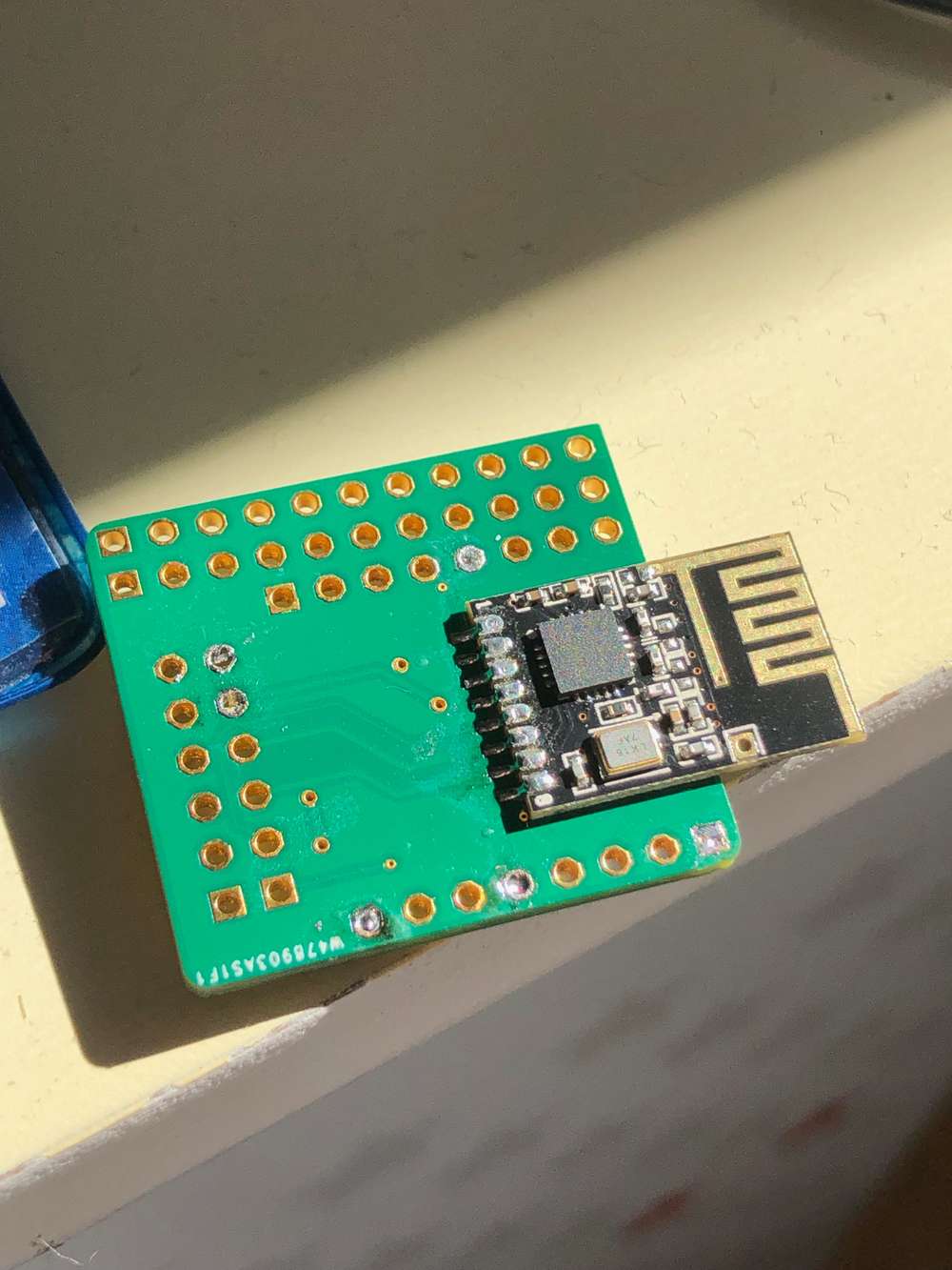
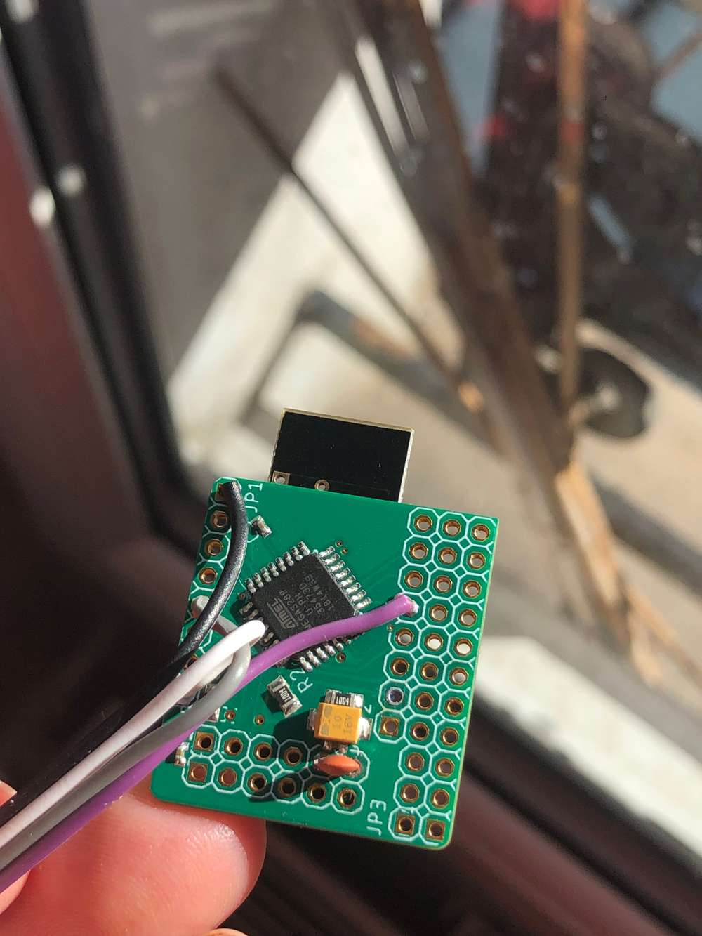
@qqlapraline here are the pictures of my PCB. Front and Back.

QQ.
-
@qqlapraline here are the pictures of my PCB. Front and Back.
QQ.
@qqlapraline I’m far from an expert, but it looks good to me. Clean and simple, not much that should be able to go wrong :-)
Maybe the distance between the capacitor and the radio is a bit long (depending on how wide the traces are I guess).
Maybe try to temporarily add another capacitor close to vcc and gnd on the radio, and see if it helps?
-
@qqlapraline I’m far from an expert, but it looks good to me. Clean and simple, not much that should be able to go wrong :-)
Maybe the distance between the capacitor and the radio is a bit long (depending on how wide the traces are I guess).
Maybe try to temporarily add another capacitor close to vcc and gnd on the radio, and see if it helps?
@mfalkvidd guess what…the capacity strikes again. I’ve soldered a 47uF right on the nrf24l01+ pins and…it works.
Would someone explain me the logic there ? The traces between the pins and the capacity were like 10mm long max.
Oh well.Qq.
-
@mfalkvidd guess what…the capacity strikes again. I’ve soldered a 47uF right on the nrf24l01+ pins and…it works.
Would someone explain me the logic there ? The traces between the pins and the capacity were like 10mm long max.
Oh well.Qq.
I plugged a Nano into a nano carrier and connected an nRF24l01 to the carrier. I never got it to work well, but had some improvement when I surrounded all the leads with aluminum foil.
I soldered a 30cm section of cat 5 cable to the nano, put a connector on the other end soldered a connector. On the radio I soldered right angle pins and a 10μ electrolytic cap between GND and VCC and that worked great! Also, used 10cm of ribbon cable between an RPi and the same radio and that worked great, too!
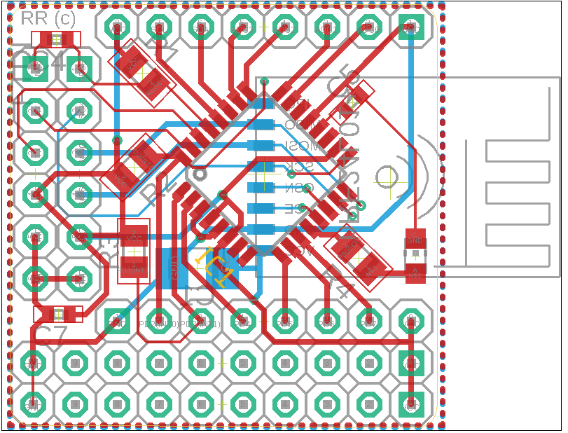
You might consider making one side of your PCB a ground plane. And/or the other side a 5V or 3.3V plane.
-
@mfalkvidd guess what…the capacity strikes again. I’ve soldered a 47uF right on the nrf24l01+ pins and…it works.
Would someone explain me the logic there ? The traces between the pins and the capacity were like 10mm long max.
Oh well.Qq.
@qqlapraline said in Find Parent (yeah, I know):
@mfalkvidd guess what…the capacity strikes again. I’ve soldered a 47uF right on the nrf24l01+ pins and…it works.
Would someone explain me the logic there ? The traces between the pins and the capacity were like 10mm long max.
Oh well.Qq.
It could be any number of causes. Just a WAG, but maybe high ESR on your tantalum capacitor together with what looks like crusty solder joints?
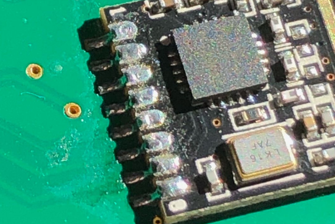
Consider using X7R low-ESR ceramic caps instead, plus putting the bypass caps as close as possible to VCC and GND on the radio. Your serial power supply might be throwing off a lot of noise as well. Check it on an o-scope. -
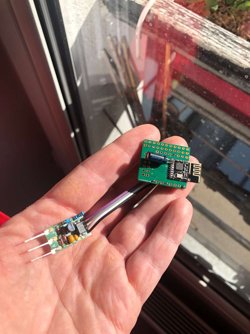
You are right, @NeverDie. Actually, my power supply is coming from a french power meter, that means a lot of noise - as I'm DC from a 50Khz AC :). So, I did two things. Adding a 330 pF capacitor at the entry point of my board and a 47µF right next to the NRF24.
Finally, I've upgrade my design to add a tantalium capacitor right next to the smd pads.
Global view:
Zooming the back with the polarized capacity (old fashion):
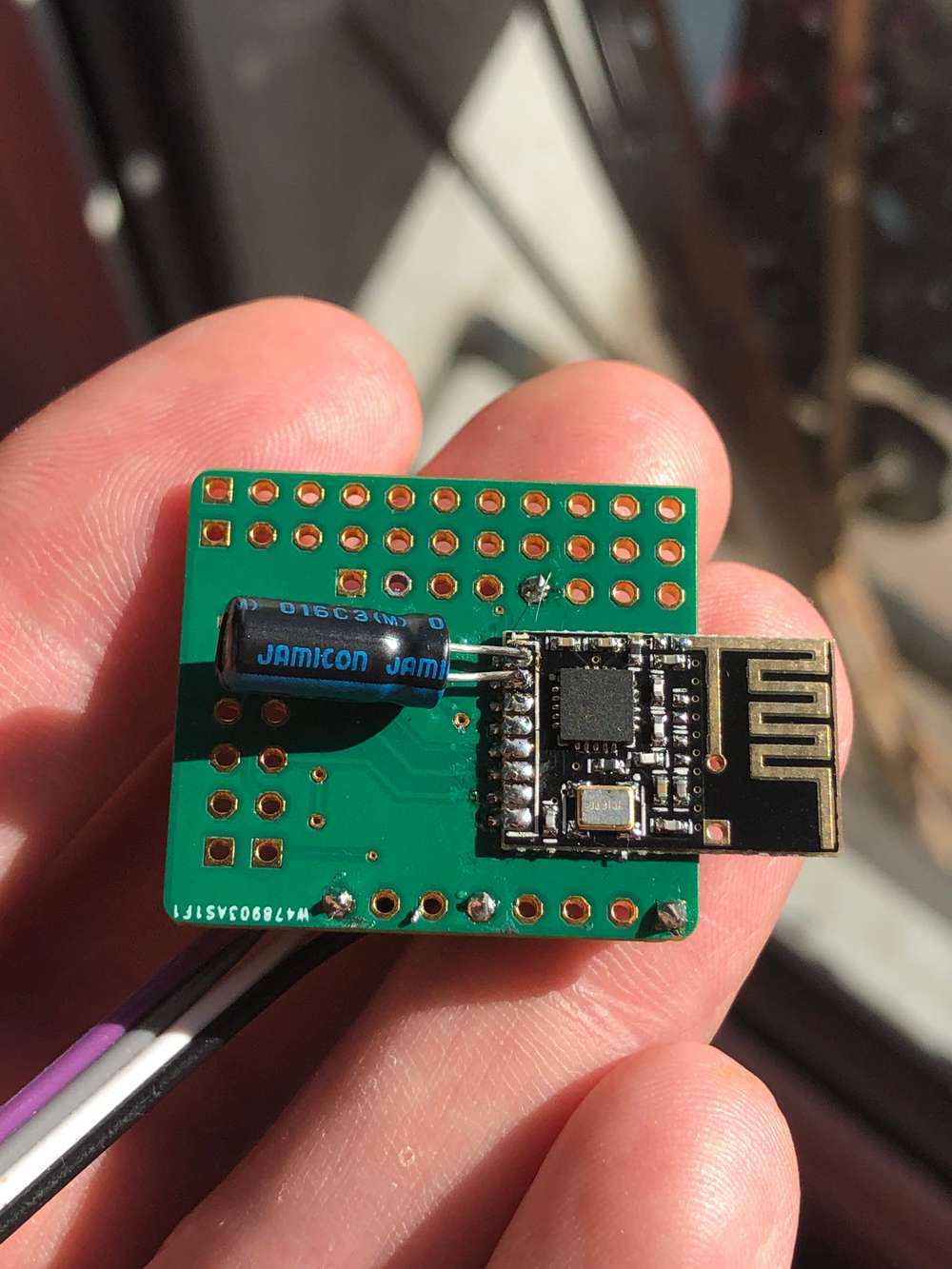
Front view:
New design:
Cheers,
QQ
Hello! It looks like you're interested in this conversation, but you don't have an account yet.
Getting fed up of having to scroll through the same posts each visit? When you register for an account, you'll always come back to exactly where you were before, and choose to be notified of new replies (either via email, or push notification). You'll also be able to save bookmarks and upvote posts to show your appreciation to other community members.
With your input, this post could be even better 💗
Register Login