Eagle files for a MeanPenguin MySensors PCB
-
absolutely great! waiting for your files to be piblished to, finally, start building!
-
The board tested good.
I have some small changes I would make for the next version but this board is good enough to start building...
The files are attached in the first post.
You you make enhancements, please share your enhancements so everyone else can benefit.Thanks
Edward -
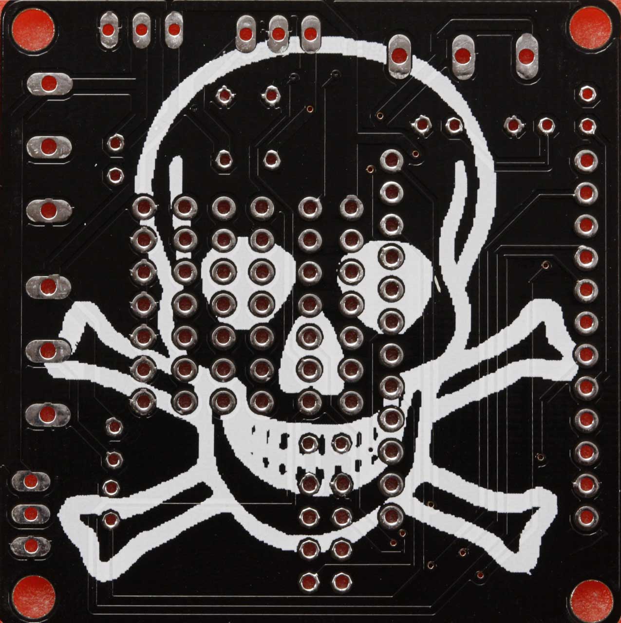
So, I ordered a test batch from DirtyPCBs (Protopack ±10). We'll see how it goes. I felt that their dirty fab needed more of a challenge so I added some completely useless silkscreen graphic to the back and rounded the corners of the pcb. Very interested to see how they react (I guess they love it when people submit silkscreen that covers pads etc) and how the board turns out. I did see in a couple of reviews that their alignment of silkscreen and mask in particular can be a bit off. No big deal I suppose.
Thanks again for your design work.
-
Just ordered some boards. Look forward to tinkering! Thanks!
-
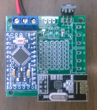
I just wanted to post some pictures of the boards I got two weeks ago. 12 boards all in all from DirtyPCBs. Sure took its time. Processing time was under a week I think, but shipping was characteristically slow. The silk screen turned out a bit wonky since I exported too many layers (duh!) and it is a bit fuzzy in other places but other than that the boards seem fine. Since it was my first ever order of PCBs I took the liberty to add a big silk screen on the back and round the corners, just to test them out. Clearly not an issue for this fab at least.
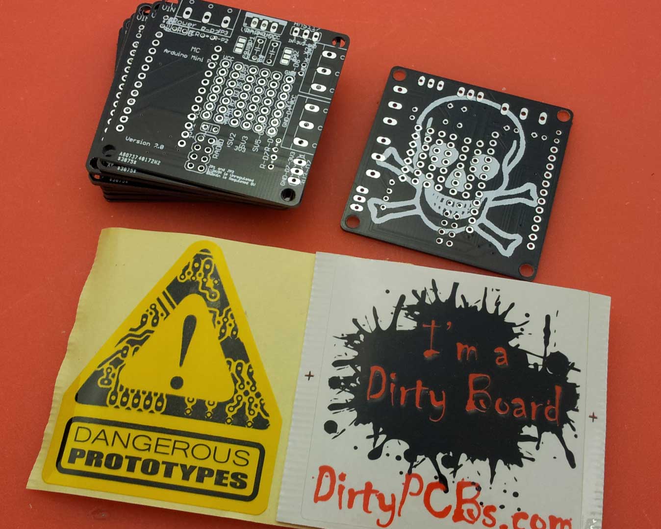
The boards are 1.2mm btw. Their standard thickness. But a bit thinner than the "usual" PCB. I like it though. Unless there is a reason to go with thicker boards?
-
I like it!
-
How would I go about acquiring some of these?
-
Hello and congrats for your great work.
I was looking at your eagle files and i was wondering...
Is there a reason you chose not to use arduino's RAW input which already has a built in voltage regulator and went with 7805 voltage regulator + capacitors?The reason i'm asking this is is because i always use a 4-1 senor (temp, hum, motion and LED dimmer) which requires 12v input so 12v dcc is a must have with this kind of setup.
-
How do I order these? I went to http://imall.iteadstudio.com/open-pcb/pcb-prototyping/im120418002.html but not sure what I need to fill in. Any aliexpress/ebay links to the headers/other components?
-
Hello and congrats for your great work.
I was looking at your eagle files and i was wondering...
Is there a reason you chose not to use arduino's RAW input which already has a built in voltage regulator and went with 7805 voltage regulator + capacitors?The reason i'm asking this is is because i always use a 4-1 senor (temp, hum, motion and LED dimmer) which requires 12v input so 12v dcc is a must have with this kind of setup.
Needed to regulate the input voltage for the radio.
It was mentioned that the radio should NOT be powered through the on-board Regulator.
-
Can you tell me how these behave?
Are you satisfied with them? -
Hi,
Any feedback would be appreciated before I send it off to be produced.
Attached are the Schematic and the Layout and will be updated as changes are made from the suggestions.Using various entries in the Forum and using this as a starting point (thanks @THERICK), this is what I have...
http://forum.mysensors.org/topic/205/my-ideal-sensor-node-pcb/22##Size##
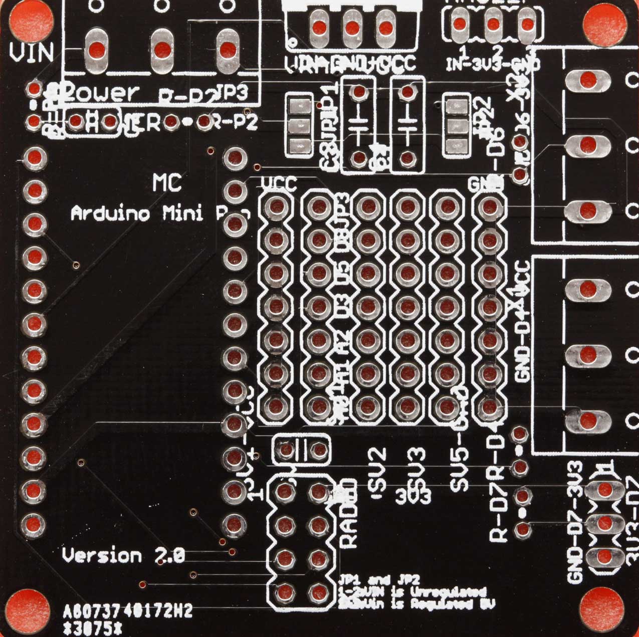
5cm x 5cm##Power##
If using 5V Regulated- Use 5V Arduino Pro Mini
- Connect pins 1 and 2 on Jumper 1
- Connect pins 1 and 2 on Jumper 2
- VCC is 5V
- Install AMS1117
- +3V3 is 3.3 volts
If using 3.3V Regulated
- Use 3V3 Arduino Pro Mini
- Connect pins 2 and 3 on Jumper 1
- Connect pins 2 and 3 on Jumper 2
- VCC is 3.3V
- Install a jumper wire across IN and OUT pins labeled for the AMS1117 (Don't install the AMS1117)
- +3V3 is 3.3 volts
- No 5v sensors
Using Unregulated > 5V
- Use 5V Arduino Pro Mini
- Connect pins 1 and 2 on Jumper 1
- Connect pins 1 and 2 on Jumper 2
- Install the LM7805 (Vin pin on left, Vout pin on right)
- Use capacitors (C3, C4) as needed
- VCC is 5 volts
- Install AMS1117
- +3V3 is 3.3 volts
##Data Pins##
Right edge of the board- Two digital pins on 3v3 with optional pull-up resistor.
- One digital pins on VCC with optional pull-up resistor.
Center of the board Mini Proto area (Columns from Left to Right)
- VCC
- Data pins (A0, A2, A2, D3, D5, D8)
- Independent holes 3 x 7
- GND
##Required Bill or Materials##
1 x Arduino Pro Mini (5V or 3V3 depending on the supply power and sensor requirements)
1 x NRF24L01+ 2.4GHz Wireless Transceiver
1 x Capacitor for the Radio across 3V3 and Gnd
1 x AMS1117 5V-3.3V Step Down Module (If NOT supplying 3v3 regulated power)##Optional##
1 x 7805 + Capacitors if not providing regulated power
PCB Mount 3 Pin Plug-in Screw Terminal Block for Power In and Data pins on the Right side of the board
Female pin headers for the Arduino and the Radio
Sensors
Pull-up resistorsPanelized Gerber file sent to ITead: ArduinoMiniProBoard v2-Panel-Gerber 2014-11-04.zip [Order the 5cmx10cm board for $15, which gives you 10 boards you cut in half to make 20] (http://imall.iteadstudio.com/open-pcb/pcb-prototyping/im120418002.html).
Note: I was able to email them and ask to double the 5cmx10cm to the 10cmx10cm for $19 netting 40 boards. You would have to do more cutting. I was able to do it easily with a box cutter and a straight edge ruler.Eagle Files: ArduinoMiniProBoard-v2-0.zip
11/24/2014: Tested v2 board and it is working. I have about 50 feet with 3 walls in between with not much failures. I need to see if caps will extend the range...
11/12/2014: Uploaded v2 Schematics and picture of the Board. Will post the Gerber files when I receive my board and they test OK.
10/31/2014: Found problems with the board.. Need to make a Rev 2 and retest.@meanpenugin Hi, is there a chance to get 1-2 or more of your PCBs. Maybe you have some left? I'ld like to test it and and maybe order some of them later.
Great work, thanks! -
Finally began tinkering with the boards I ordered a couple of months ago. Built 2, using regulated 5V. Both tell me they cannot init radio. I have yet to pull out the multimeter and begin diagnosing, but wanted to post up and see if anyone else has experienced this? I have not actually come across this error before with MySensors. I did solder pin 1 and 2 on the two pads, attached a 5v to 3.3 volt step down, cap in the slot direct above the radio. Blanking on what could be wrong, other than something witht he baords I received.
Hello! It looks like you're interested in this conversation, but you don't have an account yet.
Getting fed up of having to scroll through the same posts each visit? When you register for an account, you'll always come back to exactly where you were before, and choose to be notified of new replies (either via email, or push notification). You'll also be able to save bookmarks and upvote posts to show your appreciation to other community members.
With your input, this post could be even better 💗
Register Login