Controlling Blinds.com RF Dooya Motors with Arduino and Vera
-
I'm trying to do the same but my RF code is different. The number of bits is the same. I have first 20 bits witch I can set for remote 1;2;3 but the last 20 bits depands on command.
I delete remote1Bits4, and channel (child_Id) and add eightBits action1;2;3 for up\down\stop But it dont work.
Could you check this code changes, please?Remote 1
1100 01111100 01001000 00110000 0011 01011110 up
1100 01111100 01001000 10100000 0011 01010111 stop
1100 01111100 01001000 10000000 0011 01010100 down
Remote2
0100 01110010 01001000 00110000 0011 01011110 up
0100 01110010 01001000 10100000 0011 01010111 stop
0100 01110010 01001000 10000000 0011 01010100 down
Remote3
1110 00100100 01001000 00110000 0011 11101000 up
1110 00100100 01001000 10100000 0011 11100001 stop
1110 00100100 01001000 10000000 0011 11100011 down/* // This program is free software; you can redistribute it and/or // modify it under the terms of the GNU General Public License // version 2 as published by the Free Software Foundation. // // DESCRIPTION // This sketch provides a way to control blinds from www.blinds.com using a 433MHz RF // signal. The motors in the blinds are Dooya DV24CE motors. // // Watch a video of everything working together here: https://www.youtube.com/watch?v=EorIqw-9eJw // // The sketch is based on Henrik Ekblad's <henrik.ekblad@gmail.com> MySensors project // (http://www.mysensors.org). Credit also goes to Ray (http://rayshobby.net/?p=3381) // for instruction on how to decode the RF signal from the remote as well as code for // sending the RF signal. // // Developed by Pete B. // // REVISION HISTORY // Version 1.0 - March 19, 2014 - Original Program // Version 1.1 - April 17, 2014 - Added support for multiple remotes that are programmed from blinds.com // Version 1.2 - May 16, 2014 - Added gw.send() to update Vera blinds up/down status // Version 1.3 - Nov 21, 2014 - Upgraded code to work with MySensors v1.4 */ //Include Vera related libraries #include <MySensor.h> #include <SPI.h> #include <EEPROM.h> #include <RF24.h> //Define Constants #define SEND_DATA 3 //Data pin for RF Transmitter #define ZERO_HIGH 395 //Delay for the high part of a 0 in microseconds #define ZERO_LOW 687 //Delay for the low part of a 0 in microseconds #define ONE_HIGH 750 //Delay for the high part of a 1 in microseconds #define ONE_LOW 333//Delay for the low part of a 1 in microseconds //Vera related constants // Set NODE_ID to something unique in your sensor network (1-254) // or set to AUTO if you want gw to assign a NODE_ID for you. #define NODE_ID auto /* //List all your blinds here. These will have to be added as child nodes in setup() //The numbers will be used to assign the different remotes in the remote() method //So, make a note of which blind uses which remote then add it to the if statement //in remote(). This is referred to as the blindNumber in remote(). */ #define NUMBER_OF_BLINDS 3 //Child Node Numbers //Family Room = Node 1, Remote 2, Channel 1 //Kitchen = Node 2, Remote 2, Channel 2 //Dining Room = Node 3, Remote 2, Channel 3 //Kid's Room = Node 4, Remote 1, Channel 1 //Kids's Room = Node 5, Remote 1, Channel 2 //Guest Room = Node 6, Remote 1, Channel 3 //Master Bedroom = Node 7, Remote 1, Channel 4 //Master Closet = Node 8, Remote 1, Channel 5 //Living Room = Node 9, Remote 2, Channel 4 MySensor gw; /* //These 28 standard bits appear at the beginning of each transmit sequence: //0111011100000101010111001011. They are then followed by 12 other //bits depending on the command being sent to the blind. These bits //distinguish between the different remotes. //Because I'm not good at Arduino coding I needed to use someone else's //code to send the bits. They only used 8 bits and I couldn't get any //more to send. Because if this I have broken up the 28 bits into 8 bit //sections. Make sure to put 4 zeros at the beginning of the first //sequence. They will be ignored later in the code. //I added support for multiple remotes so you don't have to reprogram //anything when you buy more blinds. Just add the additional remote codes. */ //Remote One unsigned char remote1Bits1 = 0b00001100; //integer value of the 28 bit standard sequence referenced above. "0b" prefix is for ?? unsigned char remote1Bits2 = 0b01111100; unsigned char remote1Bits3 = 0b01001000; //Remote Two unsigned char remote2Bits1 = 0b00000100; //integer value of the 28 bit standard sequence referenced above. "0b" prefix is for ?? unsigned char remote2Bits2 = 0b01110010; unsigned char remote2Bits3 = 0b01001000; //Remote Three unsigned char remote3Bits1 = 0b00001110; //integer value of the 28 bit standard sequence referenced above. "0b" prefix is for ?? unsigned char remote3Bits2 = 0b00100100; unsigned char remote3Bits3 = 0b01001000; //Remote codes will be put in standardBits with remote() method, depending on which remote is used unsigned char standardBits1 = 0b00000000; unsigned char standardBits2 = 0b00000000; unsigned char standardBits3 = 0b00000000; void setup() { gw.begin(incomingMessage, NODE_ID); // Send the sketch version information to the gateway and Controller gw.sendSketchInfo("Blind Control", "1.3"); // Register sensors to gw (they will be created as child devices) for (int i = 0; i < NUMBER_OF_BLINDS; i++) { gw.present(i + 1, S_COVER); } } void loop() { gw.process(); } void incomingMessage(const MyMessage &message) { Serial.print("Blind Channel: "); Serial.println(message.sensor); Serial.print("Message Data: "); Serial.println(message.data); Serial.print("Message Type: "); Serial.println(message.type); int incomingBlindData = atoi(message.data); if (message.type == V_STOP) //Stop { //unsigned char i; for(uint8_t i = 0; i < 2; i++) { blindAction(message.sensor, 3); //blindAction(channel, action) action: 1=up, 2=down, 3=stop delay(50); } Serial.println("STOP command"); } else if(incomingBlindData == 100 || message.type == V_UP) //100 = Open/Up { //unsigned char i; for(uint8_t i = 0; i < 2; i++) { blindAction(message.sensor, 1); delay(50); } Serial.println("UP command"); //gw.sendgw.send(message.sensor, V_DIMMER, 100); // Update Vera with status of blinds (up/down) MyMessage blindMsg(message.sensor, V_DIMMER); //may need to assign message.sensor to a variable if this doesn't work gw.send(blindMsg.set(100)); // Update Vera with status of blinds (up/down) } else if (incomingBlindData == 0 || message.type == V_DOWN) //0 = Closed/Down { //unsigned char i; for(uint8_t i = 0; i < 2; i++) { blindAction(message.sensor, 2); delay(50); } Serial.println("DOWN command"); MyMessage blindMsg(message.sensor, V_DIMMER); //may need to assign message.sensor to a variable if this doesn't work //gw.send(message.sensor, V_DIMMER, 0); // Update Vera with status of blinds (up/down) gw.send(blindMsg.set(0)); // Update Vera with status of blinds (up/down) } } void remote(int remoteNum) { if (remoteNum == 1) //Which remote will be used? { standardBits1 = remote1Bits1; //Assign remote specific codes to standardBits variable used throughout the code standardBits2 = remote1Bits2; standardBits3 = remote1Bits3; } else if { standardBits1 = remote2Bits1; //Assign remote specific codes to standardBits variable used throughout the code standardBits2 = remote2Bits2; standardBits3 = remote2Bits3; } else { standardBits1 = remote3Bits1; //Assign remote specific codes to standardBits variable used throughout the code standardBits2 = remote3Bits2; standardBits3 = remote3Bits3; } } void fourBits(unsigned char bits) { unsigned char i; int delayTime; for(i = 0; i < 4; i++) { int highTime; int lowTime; delayTime = ((bits >> (3 - i)) & 1 ? 1 : 0); if (delayTime == 1) { highTime = ONE_HIGH; lowTime = ONE_LOW; } else { highTime = ZERO_HIGH; lowTime = ZERO_LOW; } digitalWrite(SEND_DATA, HIGH); delayMicroseconds(highTime); digitalWrite(SEND_DATA, LOW); delayMicroseconds(lowTime); } } void eightBits(unsigned char bits) { unsigned char k; int delayTime; for(k = 0; k < 8; k++) { int highTime; int lowTime; delayTime = ((bits >> (7 - k)) & 1 ? 1 : 0); if (delayTime == 1) { highTime = ONE_HIGH; lowTime = ONE_LOW; } else { highTime = ZERO_HIGH; lowTime = ZERO_LOW; } digitalWrite(SEND_DATA, HIGH); delayMicroseconds(highTime); digitalWrite(SEND_DATA, LOW); delayMicroseconds(lowTime); } } //Separator Delay Method (this is repeated frequently) void separatorDelay(boolean upDown) { if(upDown == true) { digitalWrite(SEND_DATA, LOW); delayMicroseconds(8020); } digitalWrite(SEND_DATA, HIGH); delayMicroseconds(4812); digitalWrite(SEND_DATA, LOW); delayMicroseconds(1479); } void endDelay() { digitalWrite(SEND_DATA, LOW); delayMicroseconds(51895); //Time of delay at the end of each sequence } void blindAction(int a) { //c or channel: Order on the remote from left to right 1-16 available //a or action: 1=up, 2=down, 3=stop unsigned char action; //8 action bits. Only the first 4 bits are used in the up/down end sequence unsigned char action2; //Last 4 bits from the up/down end sequence unsigned char action3; //Last 4 bits from the up/down end sequence if(a == 1) { action = 0b00110000; //code for up action2 = 0b00110101; action3 = 0b00001110; } else if (a == 2) { action = 0b00010001; //code for down action2 = 0b00001110; action3 = 0b00001110; } else (a == 3) { action = 0b00010001; //code for down action2 = 0b00001110; action3 = 0b00001110; } int i = 0; //first 6 transmissions are the same for each blind action (up, down & stop) while(i < 6) { separatorDelay(false); //false unless in the last part of the up or down commands fourBits(standardBits1); eightBits(standardBits2); eightBits(standardBits3); eightBits(action); fourBits(action2); eightBits(action3); i++; } if (a == 3) //If a stop command is issued just send the end delay then exit the method { endDelay(); } else //No stop issued so run through the last sequence { separatorDelay(false); //send true because we are in the up/down end sequence so there is an additional delay fourBits(standardBits1); eightBits(standardBits2); eightBits(standardBits3); eightBits(standardBits4); eightBits(action); fourBits(action2); eightBits(action3); int j = 0; while(j < 3) { separatorDelay(true); fourBits(standardBits1); eightBits(standardBits2); eightBits(standardBits3); eightBits(standardBits4); eightBits(action); fourBits(action1); eightBits(action2); j++; } endDelay(); } }``` -
@tjay4x4 I think you will find many helpful people on this forum. If you are willing to learn a little about coding there will be people to help. I have been helped many times with coding questions.
Here is what you will need to do. First, you need to decode your signals. It seems you have done this already which is great. Once you have your signals decoded correctly you can test to make sure they work correctly by sending them without using anything but an arduino. This is done with this code:
digitalWrite(SEND_DATA, HIGH);
delayMicroseconds(highTime);
digitalWrite(SEND_DATA, LOW);
delayMicroseconds(lowTime);
SEND_DATA is the digital pin on the Arduino (defined above in the code) and the highTime/lowTime is how long it will remain high and low. You could literally do that for each 1 and 0 that is in your signal to make sure you have it correct. Once you have that down you can begin breaking it down into methods and patterns like I have..
Hopefully that helps.
Pete
-
@tjay4x4 How did you determine what your codes were? Did you use a RF library or did you 'sniff' them directly?
@Dwalt said:
How did you determine what your codes were? Did you use a RF library or did you 'sniff' them directly?
I used Audacity. As written in the instructions. For each button sequentially rewriting the code. Comparing them with Blinds.com it became clear that the differences in the combinations of digits. If in the original, the first 28 are the same, I have to differ for each controller first 12 digits and last 12 digits. UP, DOWN, STOP bits are the same for all remotes. The question is how to write it to this code? But first I need to check High and Low time.
-
@Dwalt said:
How did you determine what your codes were? Did you use a RF library or did you 'sniff' them directly?
I used Audacity. As written in the instructions. For each button sequentially rewriting the code. Comparing them with Blinds.com it became clear that the differences in the combinations of digits. If in the original, the first 28 are the same, I have to differ for each controller first 12 digits and last 12 digits. UP, DOWN, STOP bits are the same for all remotes. The question is how to write it to this code? But first I need to check High and Low time.
Based on this it looks like you have 5 sets of 8 digits:
Remote 1
1100 01111100 01001000 00110000 0011 01011110 up
1100 01111100 01001000 10100000 0011 01010111 stop
1100 01111100 01001000 10000000 0011 01010100 down
Remote2
0100 01110010 01001000 00110000 0011 01011110 up
0100 01110010 01001000 10100000 0011 01010111 stop
0100 01110010 01001000 10000000 0011 01010100 down
Remote3
1110 00100100 01001000 00110000 0011 11101000 up
1110 00100100 01001000 10100000 0011 11100001 stop
1110 00100100 01001000 10000000 0011 11100011 downHere is some sample code that will allow you to test your sequence of 1s and 0s. It will run once each time the arduino is powered on. I haven't tested it but it should work ok.
Put your delay values that you are figuring out in the _HIGH defines (at the top). The RF sender should be connected to pin 3 on the arduino. Also, make sure to change the standardBits variables to what you have figured out from Audacity.
//Define Variables
#define SEND_DATA 3 //Data pin for RF Transmitter
#define ZERO_HIGH 376 //Delay for the high part of a 0 in microseconds
#define ZERO_LOW 653 //Delay for the low part of a 0 in microseconds
#define ONE_HIGH 713 //Delay for the high part of a 1 in microseconds
#define ONE_LOW 317 //Delay for the low part of a 1 in microseconds

int startUp = 1;

unsigned char standardBits1 = 0b00000111; //integer value of the 28 bit standard sequence referenced above. "0b" prefix is for *******
unsigned char standardBits2 = 0b01110000;
unsigned char standardBits3 = 0b01010101;
unsigned char standardBits4 = 0b11001011;
unsigned char standardBits5 = 0b11001011;


void setup() {

   Serial.begin(9600);

}

void loop() {
  if(startUp ==1){
  eightBits(standardBits1);
  eightBits(standardBits2);
  eightBits(standardBits3);
  eightBits(standardBits4);
  eightBits(standardBits5);
  startUp = 0;
  }

}

void eightBits(unsigned char bits){
    unsigned char k;
    int delayTime;
    for(k=0;k<8;k++) {
      int highTime;
      int lowTime;
      delayTime = ((bits>>(7-k)) & 1 ? 1 : 0);

      if (delayTime == 1){
        highTime = ONE_HIGH;
        lowTime = ONE_LOW;
      }
      else {
        highTime = ZERO_HIGH;
        lowTime = ZERO_LOW;
      }
        digitalWrite(SEND_DATA, HIGH);
        delayMicroseconds(highTime);
        digitalWrite(SEND_DATA, LOW);
        delayMicroseconds(lowTime);
    }
}
Also, when I was testing I recorded what was sent from my arduino (the above code) into Audacity so I could make sure my timings were correct.
-
This has been very useful, and I have been trying to use the same technique to see if I can control a Hunter Pacific fan that came with a Neoteric remote.
However, if anyone else is looking to sniff RF signals, you might find the discussions here very interesting:
http://www.princetronics.com/how-to-read-433-mhz-codes-w-arduino-433-mhz-receiver/Basically, you can use a 433 MHz receiver to sniff the signal without having to use a sound card etc. Would have saved me a bunch of time (but I did have fun trying to figure it out).
However, I have now come unstuck as the signal from the remote I have appears to be encrypted in some way as the signal changes every time - each button press results in a different signal being sent. I will continue to see if I can figure it out, but I don't have too much hope.
Thanks again for a very interesting project, and taking the time to write it up.
Regards,
CalvinAndHobbes -
This has been very useful, and I have been trying to use the same technique to see if I can control a Hunter Pacific fan that came with a Neoteric remote.
However, if anyone else is looking to sniff RF signals, you might find the discussions here very interesting:
http://www.princetronics.com/how-to-read-433-mhz-codes-w-arduino-433-mhz-receiver/Basically, you can use a 433 MHz receiver to sniff the signal without having to use a sound card etc. Would have saved me a bunch of time (but I did have fun trying to figure it out).
However, I have now come unstuck as the signal from the remote I have appears to be encrypted in some way as the signal changes every time - each button press results in a different signal being sent. I will continue to see if I can figure it out, but I don't have too much hope.
Thanks again for a very interesting project, and taking the time to write it up.
Regards,
CalvinAndHobbes@CalvinAndHobbes Thanks for sharing! I had originally tried to use that library to decode my remotes but it did not work. That's why I had to use the sound card. I agree though, definitely try that option first! It would be much easier.
I didn't think Hunter fans communicated at 433MHz? I was trying to find a fan control last year that would allow me to integrate with MySensors but they all looked to be communicating at other frequencies (fans were down near 419MHz if memory serves correct). That's exciting that you were able to decode it though! What remote are you using?
-
Just a note that the Hunter remotes are relatively cheap and hackable if you just want to wire your arduino's outputs to the switches on the (cracked open) remote. you may even be able to fit a pro-miny and an RF radio into your existing remote and use it manually or via HA apps...
-
@BulldogLowell I started out by opening the remote to see if I could find any useful information, and you are correct - they are very simple and should be very easy to wire up a pro-mini inside it. What I don't know is whether I can have 2 remotes on the same fan, as I don't think I will get away (by the rest of the family :-)) with hacking the one we have. It was also an interesting exercise to see if I could figure out what the remote was doing.
@petewill I am using the Neoteric remote from Hunter Pacific. Unfortunately they don't have any controllers that you can integrate in to any home automation system. I am going to contact the manufacturer to see if they will help, but I doubt it. -
@BulldogLowell I may have to go that route. It will probably be easier and cheaper for me anyway! First I need to finish the rain gauge :)
@CalvinAndHobbes Yes, that would be nice if they had some integration but doubtful. There is a z-wave controller from Leviton (Leviton VRF01-1LZ Vizia RF) but it's over $100 normally. Too much for me.
-
@petewill I looked at the Leviton controller - but I am in Australia, and they don't make an Australian version (for some reason, Z-Wave in Australia is on a different frequency).
And the fans I am using are Hunter Pacific fans made by an Australian company, and that is probably why the remote works on a different frequency. I believe Hunter and Hunter Pacific are different companies - just in case anyone gets them confused. -
I contacted the manufacturer, and they confirmed the protocol is a proprietary one, but they suggested I hack the remote directly, and even offered to send me some remotes to play with, so I am going to go down that route. The remote is very easy to hack too.
-
I have a similar challenge, to automate some fans that I have in my house. I didn't have the same luck when contacting the manufacturer. I tried to hack the radio messages using both 433Mhz and 315Mhz sniffers, but they must use a different radio, or I did something wrong.
It is relatively easy to hack my remotes and insert an Arduino + radio, however I'm thinking in other aspects before start --- Such as replacing the battery of the remote (currently a single CR2032 cell) , as it will have to be "always on" in order to listen to the gateway.
I'm also think in do a 'bi-way' interface, so instead only listem gw and 'press buttons' in the remote, the inserted arduino would also sense if any button is pressed in the remote and report it back to GW.
And my remotes uses the same key for on AND off. So unless I put another sensor nearby (or in) the fans, the gw will never 'be sure' if the fan is on or off...
Just some thoughts about the topic...
@rvendrame said:
Just some thoughts about the topic...
Thanks. I agree, there doesn't seem to be a perfect solution. For my blinds we rarely use the remotes that came with them. That way we don't need to worry about the status being incorrect. I have modified phones placed around the house we use as control panels as well as apps on our phones. But, for the most part the blinds are all controlled automatically by the light level outside. A ceiling fan would be different though I'd imagine.
-
Hi to everyone! Im very (I mean VERY) new at this, and Im far to be a programer or an specialist, Im just an enthusiastic end user willing to do all of you experts do!
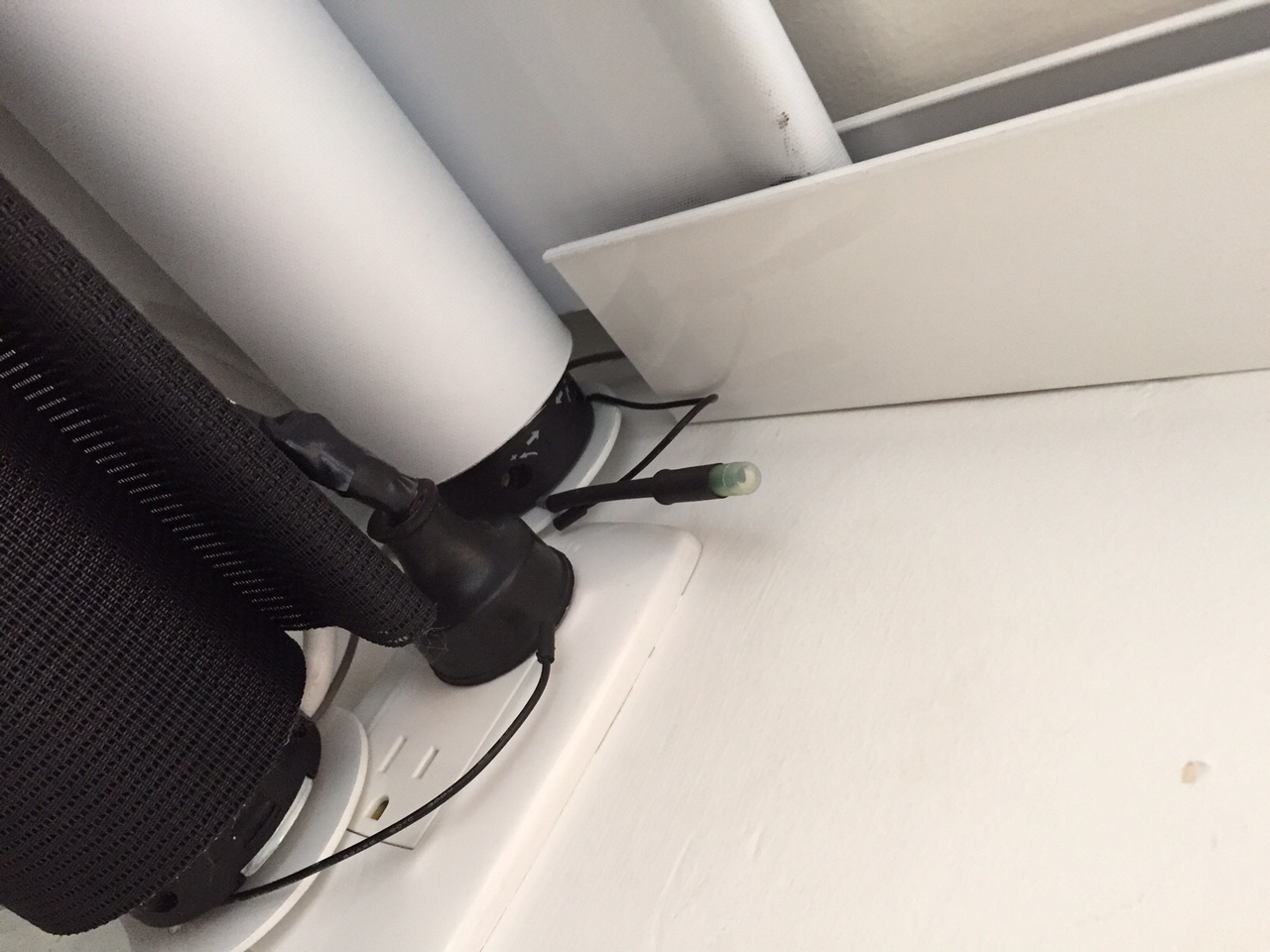
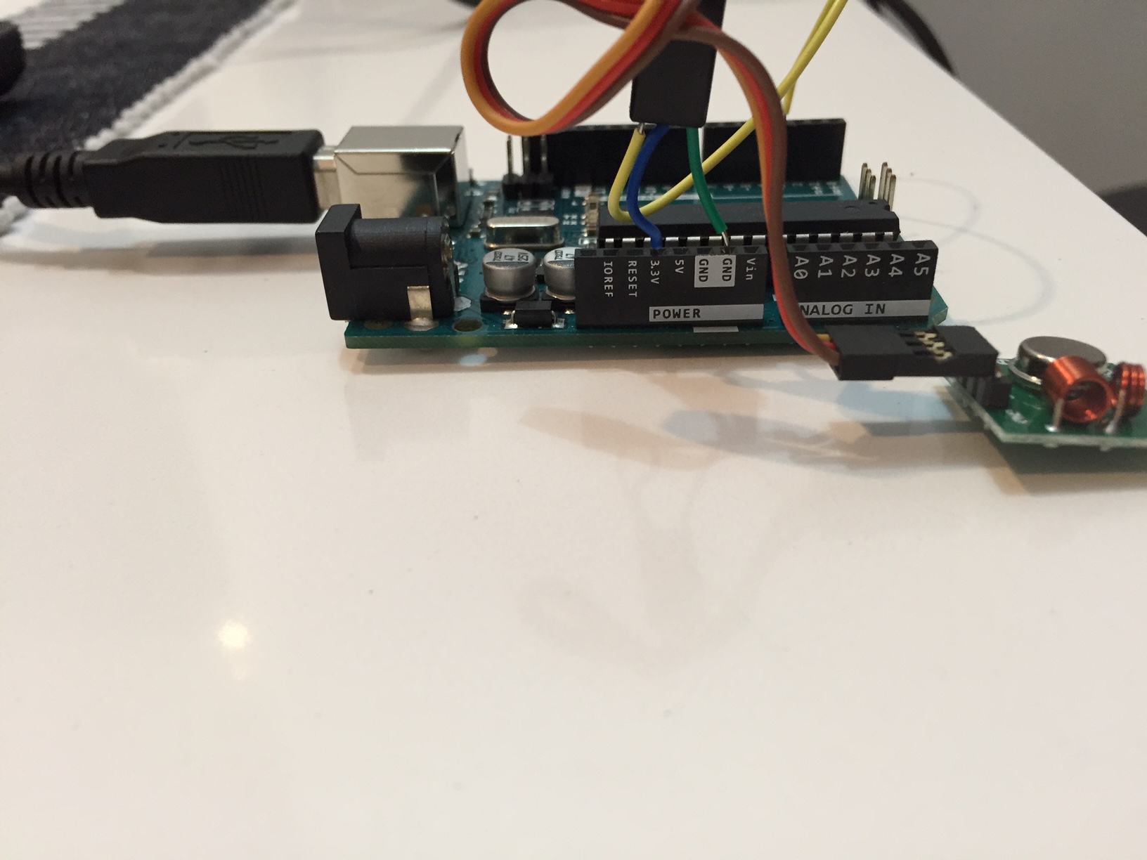
I have the same problem as Pete had, I have some dooya motors in my blinds and I want to integrate them to my smarthome system. This blinds are controlled by a remote control with 3 buttons, up – down – stop, and they are suppose to be RF, they have awesome range btw (see pics).
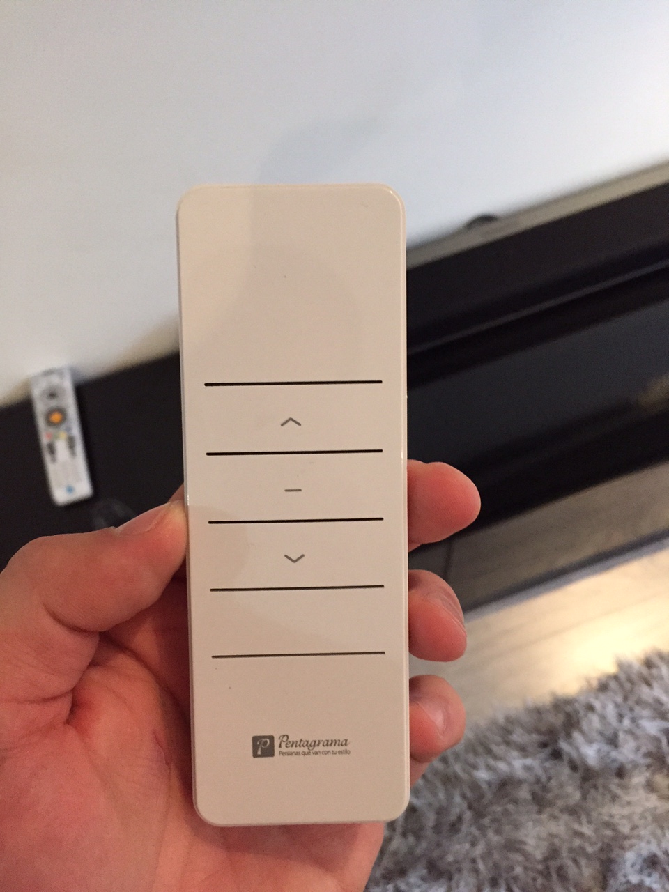
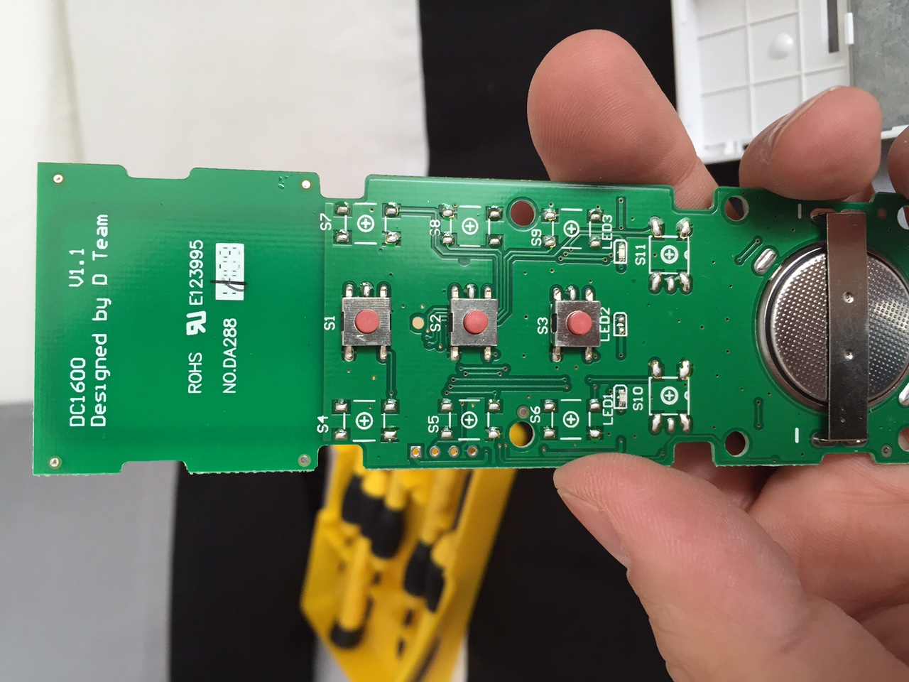
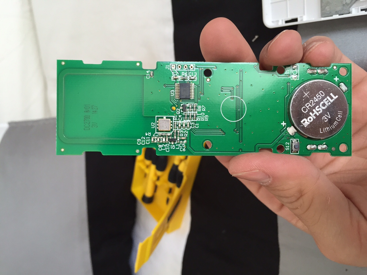
First I tried the RC-Switch to sniff the RF code, but the program return nothing, just blank, that’s why I came to this, wich I would like to thank Pete for giving a light at the end of the tunel! (which Im still in).
I did all the process to sniff the signal of the remotes, and this is what I got and traduced to binary:
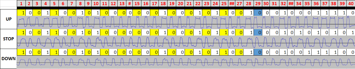
Not the same wave structure (squared) but I hope it has nothing to do.
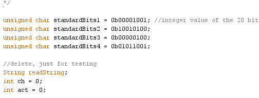
Now Im in the process of testing this code just with the Arduino, but it doesn’t work! I followed the code Pete uploaded and change the highlighted parts with my code, please let me know if I did ok, this are what I changed:
This first part, I used the first 28 bits of my signal, which is the same in the 3 comands:
Here, I used the last 8 bits for each comand:
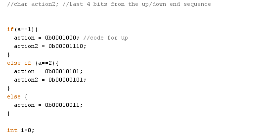
Any clues what I might be doing wrong?
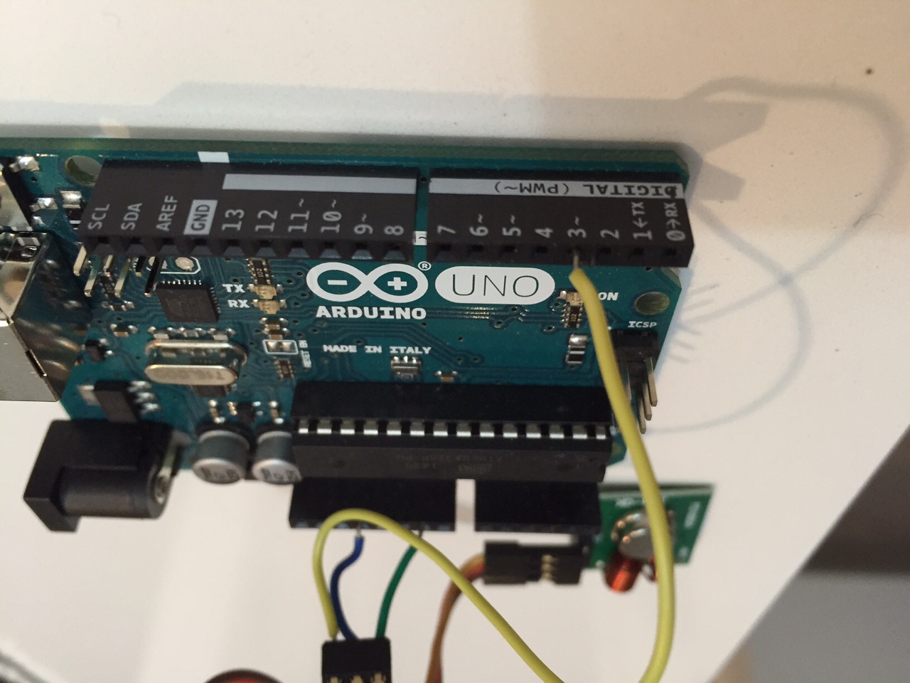
Just in case, Im using an Arduino UNO, and I connected it this way:
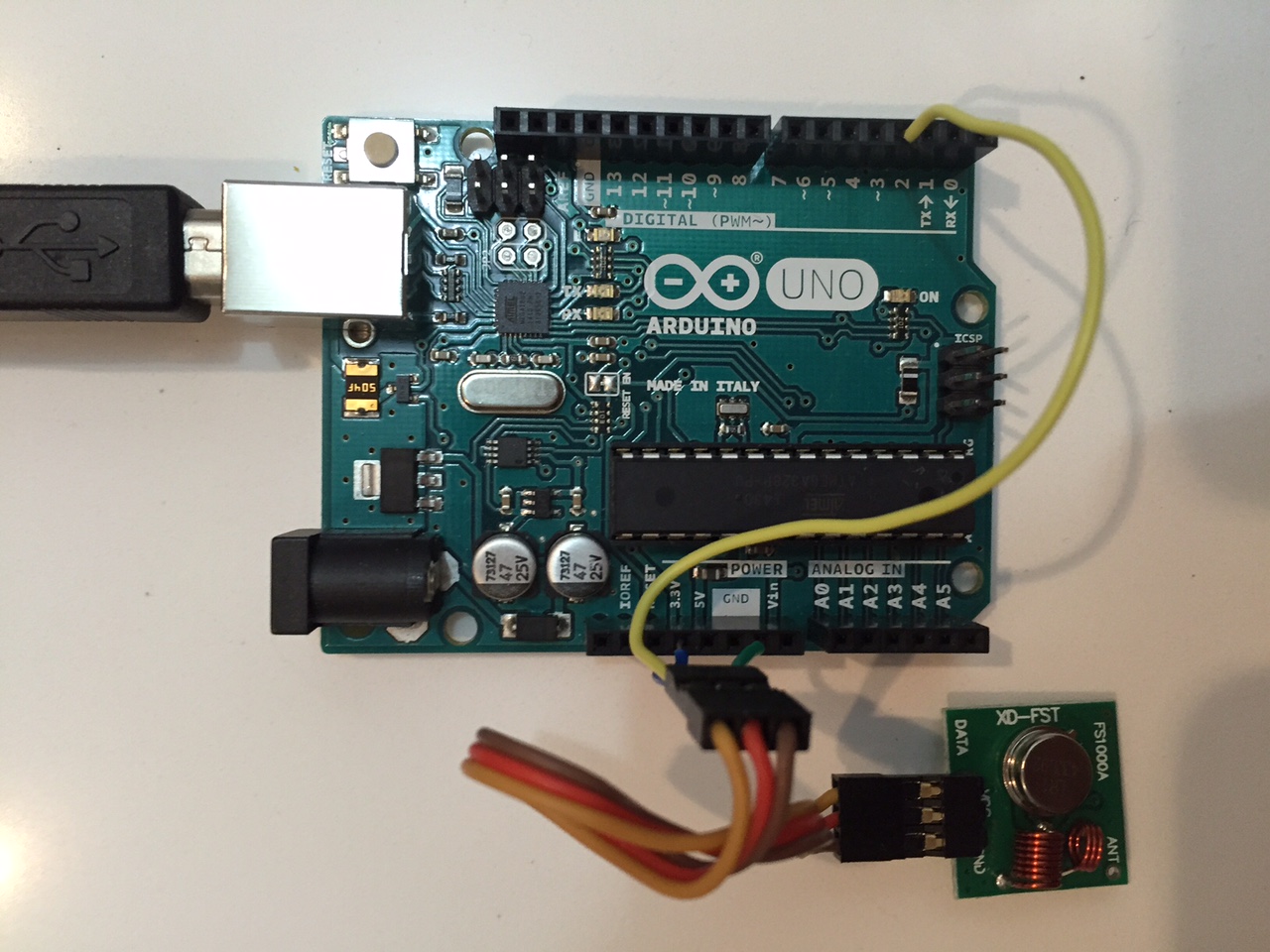
Thanks in advance!
-
Hi to everyone! Im very (I mean VERY) new at this, and Im far to be a programer or an specialist, Im just an enthusiastic end user willing to do all of you experts do!
I have the same problem as Pete had, I have some dooya motors in my blinds and I want to integrate them to my smarthome system. This blinds are controlled by a remote control with 3 buttons, up – down – stop, and they are suppose to be RF, they have awesome range btw (see pics).
First I tried the RC-Switch to sniff the RF code, but the program return nothing, just blank, that’s why I came to this, wich I would like to thank Pete for giving a light at the end of the tunel! (which Im still in).
I did all the process to sniff the signal of the remotes, and this is what I got and traduced to binary:
Not the same wave structure (squared) but I hope it has nothing to do.
Now Im in the process of testing this code just with the Arduino, but it doesn’t work! I followed the code Pete uploaded and change the highlighted parts with my code, please let me know if I did ok, this are what I changed:
This first part, I used the first 28 bits of my signal, which is the same in the 3 comands:
Here, I used the last 8 bits for each comand:
Any clues what I might be doing wrong?
Just in case, Im using an Arduino UNO, and I connected it this way:
Thanks in advance!
-
@Dwalt said:
@frantona Could you post your entire sketch? Did you measure the signal timing?
Hi! Thanks for your answer. Nope, I didnt measured the signal timing. I missed it. How should I do it?
I will paste the full code this night when I arrive home, Im using the same one Pete posted few messages back.
Thanks a lot!
@frantona Here is a tutorial on figuring out the timing. Pete's sketch uses the timing (length) for the high and low of both the ones and zeros (lines 35-38).
Have you tried this with the RCSwitch or Remoteswitch libraries? They take all the guesswork out of sniffing signals although they don't work for all transmitters. [Edit: nevermind, i reread your post where you did say you tried RCSwitch].
-
What a great thread, thanks @petewill for all of the info. I can't wait to give this a try.
After reading through all of this, am I correct in assuming that using the slider control (or programming a controller to open the shade to a certain %) has not been achieved?
I was thinking about this a bit, and thought about perhaps using a few cheap magnetic door sensors along the edge of the window at different positions. You could then attach a small neodymium magnet to the back of the bottom edge of the shade that passes by the door sensors. Each of those door sensors could report a value back to the controller, indicating its position (ie 0,25,50,75,100), and if the MySensors node receives a slider value from the controller, you could round to the closest value, and raise/lower the shade until that value is achieved.
I'm a complete MySensors/HA/Vera noob, so please excuse my ignorance if this is a ridiculous solution to a simple issue. :grin:
Hello! It looks like you're interested in this conversation, but you don't have an account yet.
Getting fed up of having to scroll through the same posts each visit? When you register for an account, you'll always come back to exactly where you were before, and choose to be notified of new replies (either via email, or push notification). You'll also be able to save bookmarks and upvote posts to show your appreciation to other community members.
With your input, this post could be even better 💗
Register Login