Power strip with 4 sockets
-
Hi everyone,
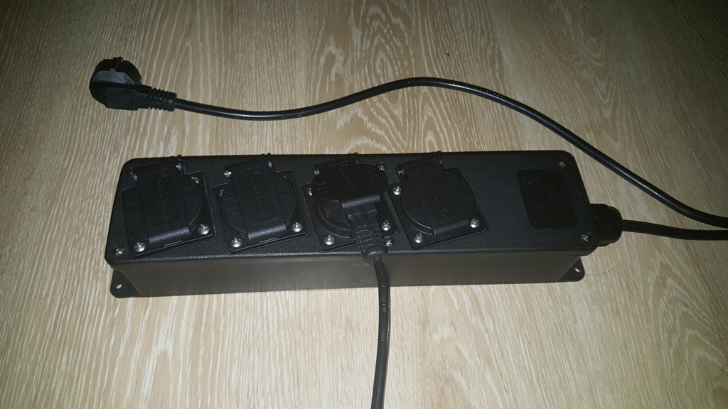
I have decided to make power strip where i can control each socket independently.Parts needed:
1x Power strip from local shop €18
1x usb charger 500mah from aliexpress €1,30
1x arduino nano aliexpress €2,80
4x relays aliexpress €4
1x radio aliexpress €0,70
And some cables €2 +-Sketch:
// Example sketch showing how to control physical relays.
// This example will remember relay state even after power failure.

#include <MySensor.h>
#include <SPI.h>

#define RELAY_1  3  // Arduino Digital I/O pin number for first relay (second on pin+1 etc)
#define NUMBER_OF_RELAYS 4 // Total number of attached relays
#define RELAY_ON 1  // GPIO value to write to turn on attached relay
#define RELAY_OFF 0 // GPIO value to write to turn off attached relay

MySensor gw;

void setup()
{
  // Initialize library and add callback for incoming messages
  gw.begin(incomingMessage, AUTO, true);
  // Send the sketch version information to the gateway and Controller
  gw.sendSketchInfo("Stekkerdoos", "1.0");

  // Fetch relay status
  for (int sensor=1, pin=RELAY_1; sensor<=NUMBER_OF_RELAYS;sensor++, pin++) {
    // Register all sensors to gw (they will be created as child devices)
    gw.present(sensor, S_LIGHT);
    // Then set relay pins in output mode
    pinMode(pin, OUTPUT);
    // Set relay to last known state (using eeprom storage)
    digitalWrite(pin, gw.loadState(sensor)?RELAY_ON:RELAY_OFF);
  }
}


void loop()
{
  // Alway process incoming messages whenever possible
  gw.process();
}

void incomingMessage(const MyMessage &message) {
  // We only expect one type of message from controller. But we better check anyway.
  if (message.type==V_LIGHT) {
     // Change relay state
     digitalWrite(message.sensor-1+RELAY_1, message.getBool()?RELAY_ON:RELAY_OFF);
     // Store state in eeprom
     gw.saveState(message.sensor, message.getBool());
     // Write some debug info
     Serial.print("Incoming change for sensor:");
     Serial.print(message.sensor);
     Serial.print(", New status: ");
     Serial.println(message.getBool());
   }
}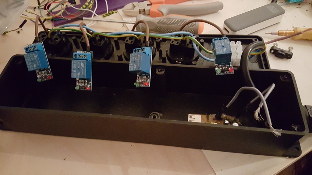
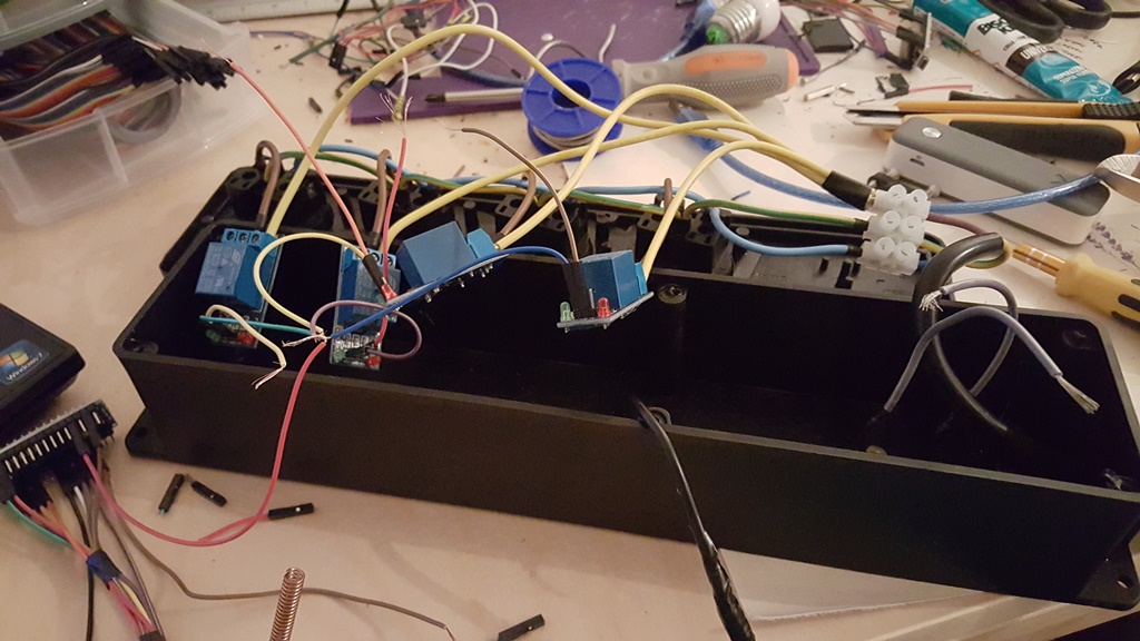
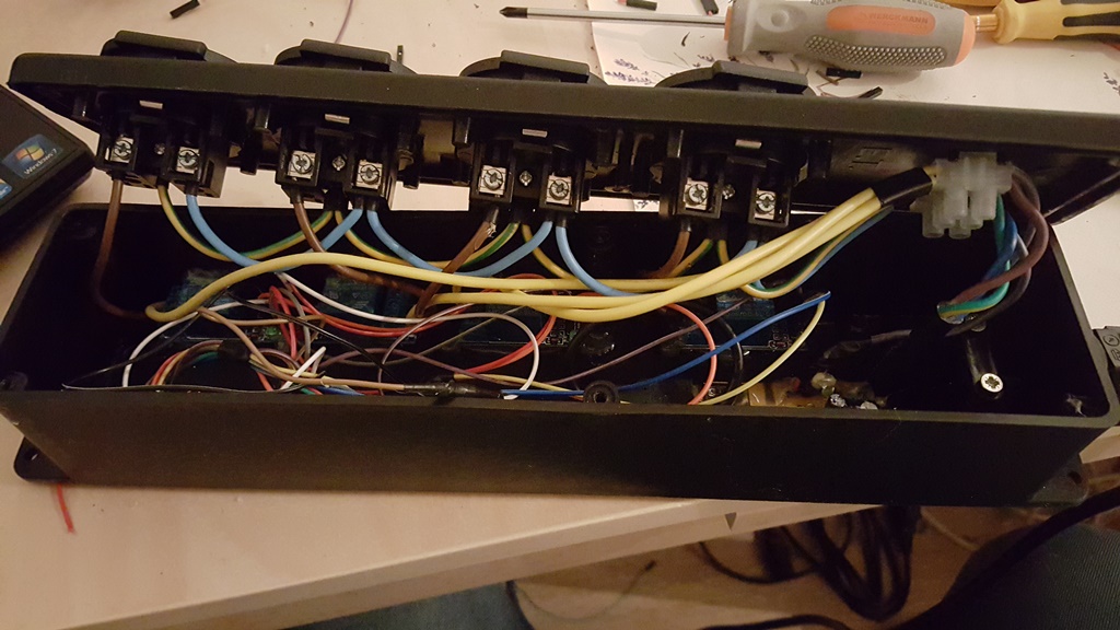
Next step is add led to each socket so that i know which one is on and maybe add buttons for manually control
-
Hi everyone,
I have decided to make power strip where i can control each socket independently.Parts needed:
1x Power strip from local shop €18
1x usb charger 500mah from aliexpress €1,30
1x arduino nano aliexpress €2,80
4x relays aliexpress €4
1x radio aliexpress €0,70
And some cables €2 +-Sketch:
// Example sketch showing how to control physical relays.
// This example will remember relay state even after power failure.

#include <MySensor.h>
#include <SPI.h>

#define RELAY_1  3  // Arduino Digital I/O pin number for first relay (second on pin+1 etc)
#define NUMBER_OF_RELAYS 4 // Total number of attached relays
#define RELAY_ON 1  // GPIO value to write to turn on attached relay
#define RELAY_OFF 0 // GPIO value to write to turn off attached relay

MySensor gw;

void setup()
{
  // Initialize library and add callback for incoming messages
  gw.begin(incomingMessage, AUTO, true);
  // Send the sketch version information to the gateway and Controller
  gw.sendSketchInfo("Stekkerdoos", "1.0");

  // Fetch relay status
  for (int sensor=1, pin=RELAY_1; sensor<=NUMBER_OF_RELAYS;sensor++, pin++) {
    // Register all sensors to gw (they will be created as child devices)
    gw.present(sensor, S_LIGHT);
    // Then set relay pins in output mode
    pinMode(pin, OUTPUT);
    // Set relay to last known state (using eeprom storage)
    digitalWrite(pin, gw.loadState(sensor)?RELAY_ON:RELAY_OFF);
  }
}


void loop()
{
  // Alway process incoming messages whenever possible
  gw.process();
}

void incomingMessage(const MyMessage &message) {
  // We only expect one type of message from controller. But we better check anyway.
  if (message.type==V_LIGHT) {
     // Change relay state
     digitalWrite(message.sensor-1+RELAY_1, message.getBool()?RELAY_ON:RELAY_OFF);
     // Store state in eeprom
     gw.saveState(message.sensor, message.getBool());
     // Write some debug info
     Serial.print("Incoming change for sensor:");
     Serial.print(message.sensor);
     Serial.print(", New status: ");
     Serial.println(message.getBool());
   }
}
Next step is add led to each socket so that i know which one is on and maybe add buttons for manually control
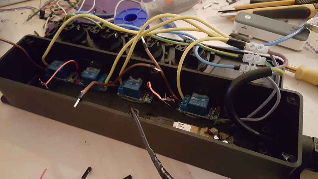
@miremi if the sockets are on for long periods i would recommend you to switch to bistable relays. The downside is that they are more expensive and need two pins. However, unlike these relays the do not consume electricity while on and do not heat up.
-
@ Moshe Livne this one is only for some lights in garden with total consumption of 200w.
I'm using it now for about a week with no problem and temperature of relays is about 30c even tested it with load of 2100w for about six hours with no heating problems. -
I havent added up your cost but I have one of these from Ubiquity...works like a charm..
-AM
-
@ Moshe Livne this one is only for some lights in garden with total consumption of 200w.
I'm using it now for about a week with no problem and temperature of relays is about 30c even tested it with load of 2100w for about six hours with no heating problems.@miremi so all is good.... I had a feeling that mine gets closer to 40c (touch warm, like feverish child....) and would be concerned about heat buildup of so many in closed enclosure
-
Awesome project man,
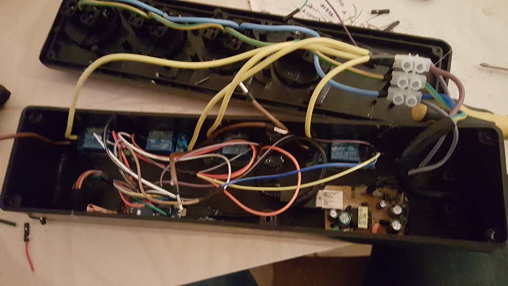
If you can add Buttons for manual control and an LED it would make it complete.Looking forward to that.
-
Hi everyone,
I have decided to make power strip where i can control each socket independently.Parts needed:
1x Power strip from local shop €18
1x usb charger 500mah from aliexpress €1,30
1x arduino nano aliexpress €2,80
4x relays aliexpress €4
1x radio aliexpress €0,70
And some cables €2 +-Sketch:
// Example sketch showing how to control physical relays.
// This example will remember relay state even after power failure.

#include <MySensor.h>
#include <SPI.h>

#define RELAY_1  3  // Arduino Digital I/O pin number for first relay (second on pin+1 etc)
#define NUMBER_OF_RELAYS 4 // Total number of attached relays
#define RELAY_ON 1  // GPIO value to write to turn on attached relay
#define RELAY_OFF 0 // GPIO value to write to turn off attached relay

MySensor gw;

void setup()
{
  // Initialize library and add callback for incoming messages
  gw.begin(incomingMessage, AUTO, true);
  // Send the sketch version information to the gateway and Controller
  gw.sendSketchInfo("Stekkerdoos", "1.0");

  // Fetch relay status
  for (int sensor=1, pin=RELAY_1; sensor<=NUMBER_OF_RELAYS;sensor++, pin++) {
    // Register all sensors to gw (they will be created as child devices)
    gw.present(sensor, S_LIGHT);
    // Then set relay pins in output mode
    pinMode(pin, OUTPUT);
    // Set relay to last known state (using eeprom storage)
    digitalWrite(pin, gw.loadState(sensor)?RELAY_ON:RELAY_OFF);
  }
}


void loop()
{
  // Alway process incoming messages whenever possible
  gw.process();
}

void incomingMessage(const MyMessage &message) {
  // We only expect one type of message from controller. But we better check anyway.
  if (message.type==V_LIGHT) {
     // Change relay state
     digitalWrite(message.sensor-1+RELAY_1, message.getBool()?RELAY_ON:RELAY_OFF);
     // Store state in eeprom
     gw.saveState(message.sensor, message.getBool());
     // Write some debug info
     Serial.print("Incoming change for sensor:");
     Serial.print(message.sensor);
     Serial.print(", New status: ");
     Serial.println(message.getBool());
   }
}
Next step is add led to each socket so that i know which one is on and maybe add buttons for manually control
-
Nice project!
I wanted to build one myself - but have now visited three stores, and all have these power strips with special security screws! :rage: Dont want to wait for china delivery. Any ideas?
Br
Controller: Proxmox VM - Home Assistant
MySensors GW: Arduino Uno - W5100 Ethernet, Gw Shield Nrf24l01+ 2,4Ghz
MySensors GW: Arduino Uno - Gw Shield RFM69, 433mhz
RFLink GW - Arduino Mega + RFLink Shield, 433mhz -
Nice project!
I wanted to build one myself - but have now visited three stores, and all have these power strips with special security screws! :rage: Dont want to wait for china delivery. Any ideas?
Br
@sundberg84 Ha! Mine had one way screws! You can only tighten them, not untighten. A friend of mine lookef at it said no problem and just ignored the fact that it shouldn't work and opened it.
There must be a moral there somewhere.
If its star ir triangular you can buy bits for next to nothing -
Hey Man!
any progress on the buttons?
Really looking forward to that so that i can start making one for myself as well.Cheers.
Hello! It looks like you're interested in this conversation, but you don't have an account yet.
Getting fed up of having to scroll through the same posts each visit? When you register for an account, you'll always come back to exactly where you were before, and choose to be notified of new replies (either via email, or push notification). You'll also be able to save bookmarks and upvote posts to show your appreciation to other community members.
With your input, this post could be even better 💗
Register Login