Safe In-Wall AC to DC Transformers??
-
@Bertb Aaah yes now I see. It does seem to draw much more peak current than I expected! Then I'll just use the same component as I'm using for Fuse 2.
What do you mean by "The varistor is only good for the output."? You're using one as input and one as output in your diagram as well or am I missing something?And yes, I know this is Chinese stuff again.. But single (chinese) components never failed on me (until now). :smiley:
-
@Bertb I see what is getting both of us confused.
Apparently something was wrong in the link of my previous post, resulting in the 2nd varistor not being listed. So now your comment about the varistor only being good for the output makes sense as well. :smiley:
I've fixed the link of my post above! -
Short update ... yesterday I asked or Chinese friends from Alie to send a HLK module to our test friend.
I also did an insulation test with 1000 Volt. The test shows more than 1000 MOhm between ac and dc. So far so good.@Bertb said:
Short update ... yesterday I asked or Chinese friends from Alie to send a HLK module to our test friend.
I also did an insulation test with 1000 Volt. The test shows more than 1000 MOhm between ac and dc. So far so good.:+1:
-
Not a big fan of soldering SMD components and I cannot find standard components, how essential is the 2nd fuse and varistor on the 5v side?
@Atomfire said:
Not a big fan of soldering SMD components and I cannot find standard components, how essential is the 2nd fuse and varistor on the 5v side?
We are trying to make it as safer as possible... Assuming such modules will stay in a wall box, very close to wires and/or other potential fireable materials, we should try to mitigate risks as much as possible.
As I mentioned above --- This is DIY, also means 'risk it yourself'. Don't tell your insurance company ;-)
-
@Atomfire said:
Not a big fan of soldering SMD components and I cannot find standard components, how essential is the 2nd fuse and varistor on the 5v side?
We are trying to make it as safer as possible... Assuming such modules will stay in a wall box, very close to wires and/or other potential fireable materials, we should try to mitigate risks as much as possible.
As I mentioned above --- This is DIY, also means 'risk it yourself'. Don't tell your insurance company ;-)
@rvendrame said:
@Atomfire said:
Not a big fan of soldering SMD components and I cannot find standard components, how essential is the 2nd fuse and varistor on the 5v side?
We are trying to make it as safer as possible... Assuming such modules will stay in a wall box, very close to wires and/or other potential fireable materials, we should try to mitigate risks as much as possible.
As I mentioned above --- This is DIY, also means 'risk it yourself'. Don't tell your insurance company ;-)
That is why I prefer to use fuses that blow, like the ones I mentioned earlier.
The resettable fuses also get warm. Can't wait for the package from Conrad to arrive. I am dying to do some further testing.With respect to the brave HLK ... it is on for some three days and it is stable.
-
@rvendrame said:
@Atomfire said:
Not a big fan of soldering SMD components and I cannot find standard components, how essential is the 2nd fuse and varistor on the 5v side?
We are trying to make it as safer as possible... Assuming such modules will stay in a wall box, very close to wires and/or other potential fireable materials, we should try to mitigate risks as much as possible.
As I mentioned above --- This is DIY, also means 'risk it yourself'. Don't tell your insurance company ;-)
That is why I prefer to use fuses that blow, like the ones I mentioned earlier.
The resettable fuses also get warm. Can't wait for the package from Conrad to arrive. I am dying to do some further testing.With respect to the brave HLK ... it is on for some three days and it is stable.
@Bertb said:
That is why I prefer to use fuses that blow,
In the other hand, you have to disassemble the wall box in order to reach regular fuses that eventually blow. So I tend to prefer PPTCs, at least for this 'discovery' phase.
But it is just my personal preference.
-
Thanks everyone for the help! I don't know much about this stuff and I am grateful to you for all your contributions!
I am starting to look at ebay for parts but I was wondering if it would be wise to wait a little longer before I order and more testing is performed? I am excited to start building but I don't want to do anything until it's safe. I know safe is a relative term so I guess I should say safe enough for you all to use in your houses. :)
Thanks again!
Pete
-
Mine is on the way too.
-
@petewill I think this is a wise decision.
I liked the discussion on this thread, so I have to thank you too.Now it is waiting time. Waiting until the hlk-s arrive at the lab of the test guy.
My Chinese friend said, the package is on its way. -
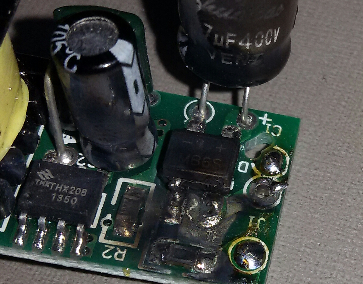
Just a heads up. Yesterday I blew up this module, which I bought some time ago (before we invest into the HLK analysis).
I really don't know what happened, it simply exploded without any further notice (and very near my face, like 30cm or so). I was calibrating the power sensor. Dummy I was, trying to find why it was measuring 10W while the PSU is rated 3W...
The sensor is based on a current transformer TA12-100 , measuring itself on ACMains.
Perhaps some old-school guy can tell me if I violated some some basic rule? I want to believe that some scrap wire or metal has shortened some track, but how to prove it?
Well after that, I measured the arduino + radio + measurement circuit and it never crossed 30mA... I also replaced the damaged PSU (by one identical), and now the power sensor measures 4W (instead the previous 10W), and despite some noising capacitor, no heat or instability after 12 hours or so on.
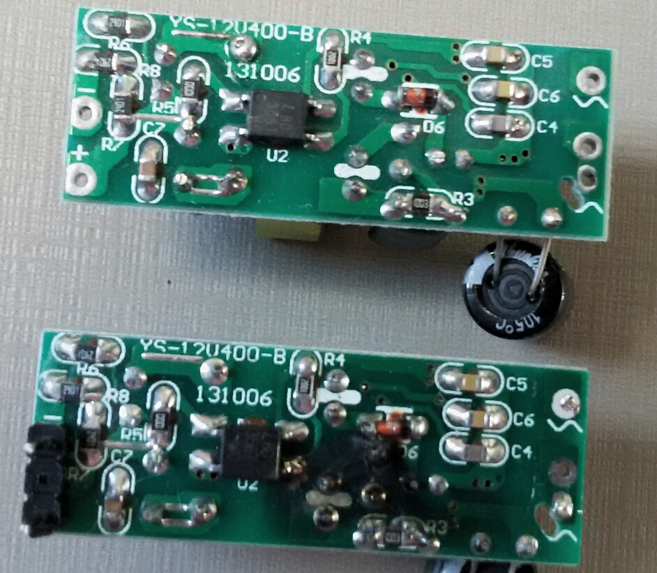
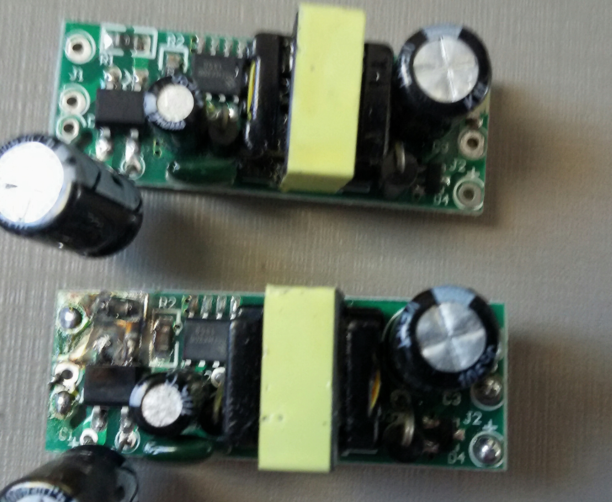
Pictures of the occurrence:
Botton one is the damaged one:
-
Just a heads up. Yesterday I blew up this module, which I bought some time ago (before we invest into the HLK analysis).
I really don't know what happened, it simply exploded without any further notice (and very near my face, like 30cm or so). I was calibrating the power sensor. Dummy I was, trying to find why it was measuring 10W while the PSU is rated 3W...
The sensor is based on a current transformer TA12-100 , measuring itself on ACMains.
Perhaps some old-school guy can tell me if I violated some some basic rule? I want to believe that some scrap wire or metal has shortened some track, but how to prove it?
Well after that, I measured the arduino + radio + measurement circuit and it never crossed 30mA... I also replaced the damaged PSU (by one identical), and now the power sensor measures 4W (instead the previous 10W), and despite some noising capacitor, no heat or instability after 12 hours or so on.
Pictures of the occurrence:
Botton one is the damaged one:
@rvendrame Whatever happened (looks like something went to ground; were you probing with a scope?), that MB6S was the source, because that rectifier is blow out.
I don't think you will be able to buff that one out... :stuck_out_tongue:
-
@ServiceXp , no
-
@rvendrame Whatever happened (looks like something went to ground; were you probing with a scope?), that MB6S was the source, because that rectifier is blow out.
I don't think you will be able to buff that one out... :stuck_out_tongue:
@ServiceXp , no oscilloscope. I was Cheking why the power sensor was measuring 10w instead 3w or less.
The CT sensor was around the mains phase wire, and the psu was powering the sensor. I didn't change anything , just multimeter readings on DC side. Didn't touch the ac mains except to insert the current transformer around it.
I also connected a light bulb on same wire, in order to generate some load. The sensor was measuring the bulb correctly, however when the bulb was disconnected it read 10w, away too much for only an arduino.
-
@ServiceXp , no oscilloscope. I was Cheking why the power sensor was measuring 10w instead 3w or less.
The CT sensor was around the mains phase wire, and the psu was powering the sensor. I didn't change anything , just multimeter readings on DC side. Didn't touch the ac mains except to insert the current transformer around it.
I also connected a light bulb on same wire, in order to generate some load. The sensor was measuring the bulb correctly, however when the bulb was disconnected it read 10w, away too much for only an arduino.
@rvendrame I'm not sure if I really get your setup, but ground loops can be a very nifty cause of all kinds of stuff getting 'too hot' :grimacing:
Could this be the cause of the problem?
That 0 ohms resistor also looks like it been fried. What's its use on the board?
-
@ServiceXp , no oscilloscope. I was Cheking why the power sensor was measuring 10w instead 3w or less.
The CT sensor was around the mains phase wire, and the psu was powering the sensor. I didn't change anything , just multimeter readings on DC side. Didn't touch the ac mains except to insert the current transformer around it.
I also connected a light bulb on same wire, in order to generate some load. The sensor was measuring the bulb correctly, however when the bulb was disconnected it read 10w, away too much for only an arduino.
@rvendrame Hard to say then, but I'd bet an ice cream sandwich that something went to ground/neutral. It's the high voltage side that is blown out of that rectifier.. You may never know what the cause was.
-
Does anyone know of any 120V AC to 5V DC transformers that are safe to put in a wall electrical box? I have been using old cell phone chargers for most of my projects but I was recently pondering putting something right in the wall. Since shipping can take so long I thought I'd ask now before I even start on the project.
I did some searching and couldn't find anything so I thought I'd ask the experts here.
Thanks in advance!
EDIT 9/7/2016
Watch out for Fakes! Read more here: https://forum.mysensors.org/topic/1607/safe-in-wall-ac-to-dc-transformers/355
If in doubt you can get them directly from the vendor here: http://www.hlktech.net/product.php?CateId=10EDIT 12/28/2015
After MUCH discussion on this here are the findings of this thread (as of now):Here is the diagram for how things should be wired:
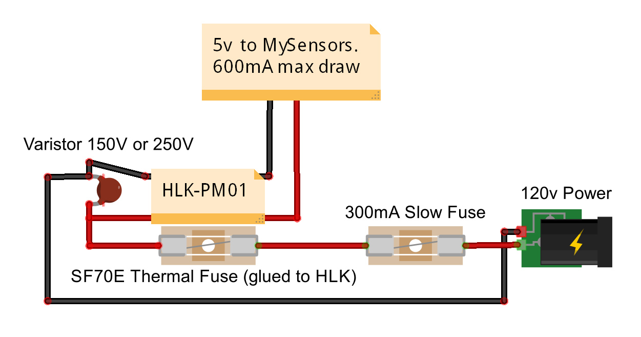
These are the parts I ordered. I haven't tested any of these parts yet as this project has been put on the back burner for now :(. I am in the USA so this is spec'd for 120 VAC. If you're using 240 you will need to change the size of the Varistor but everything else should be fine for 240.
Also, see these posts for more discussion/ideas if interested:
http://forum.mysensors.org/topic/1540/110v-230v-ac-to-mysensors-pcb-board
http://forum.mysensors.org/topic/2488/in-wall-pcbVaristor for 120VAC - http://www.ebay.com/itm/321024816822?_trksid=p2057872.m2749.l2649&ssPageName=STRK%3AMEBIDX%3AIT
73°C Thermal Fuse - http://www.ebay.com/itm/221560426284?_trksid=p2057872.m2749.l2649&var=520415979885&ssPageName=STRK%3AMEBIDX%3AIT
250V 300mA Slow Blow Fuse - http://www.ebay.com/itm/111433875797?_trksid=p2057872.m2749.l2649&var=410420838583&ssPageName=STRK%3AMEBIDX%3AIT
HLK-PM01 - http://www.ebay.com/itm/351418782712?_trksid=p2057872.m2749.l2649&ssPageName=STRK%3AMEBIDX%3AIT
Pete
Hello! It looks like you're interested in this conversation, but you don't have an account yet.
Getting fed up of having to scroll through the same posts each visit? When you register for an account, you'll always come back to exactly where you were before, and choose to be notified of new replies (either via email, or push notification). You'll also be able to save bookmarks and upvote posts to show your appreciation to other community members.
With your input, this post could be even better 💗
Register Login