Safe In-Wall AC to DC Transformers??
-
Some more thoughts from the guy who analyzed it:
"Hi Ricardo
It looks safe enough to me, except I want a fuse or fusible resistor before it. The purpose of the fuse is to blow when the module is worn down and maybe shorts. How fast it wears down will depend on temperature, at very high temperature it might be less than ½ year, at more moderate temperature it might be 10-20 years. The main culprit is the capacitors, their lifetime depends on temperature and quality of the capacitor.
Second risk for failure is large transients on the mains that may damage the module, again the fuse is there to prevent things getting out of hand if the module breaks down.The module can get hot if you pack it into the wall, especially if it is inside a lot of insulation. Doing a few test with a DMM and a temperature probe taped to the module inside the wall might be a good idea when running the module near full load.
I do not know the stuff used to fill with, but usual it will not easily catch fire." -
@rvendrame Thanks for getting this tested - that's a great result. The high temperatures he was testing at are for running at 1A of output but I thought that the 5V line is just for the Arduino and the radio which aren't going to use much current at all right?
-
@rvendrame Thanks for getting this tested - that's a great result. The high temperatures he was testing at are for running at 1A of output but I thought that the 5V line is just for the Arduino and the radio which aren't going to use much current at all right?
@TD22057 , exactly, under regular load (< 600ma), the unit should not get that hot. Once I get some time I will try the suggestion, by gluing a temp sensor on the unit and put it behind the wall switch.
Perhaps I will add the temp sensor permanently as a extra mySensor on the wall-relay, so I can capture the temp during the upcoming summer days. ;-)
-
Well, I must say, I am very happy with the result. Thanks for the testing.
So, I am already planning to use it in a number of devices. To avoid too high temperatures in confined boxes, it might be a good idea to glue a temperature fuse to it and wire it in series with the live mains wire. When the temperature rises above, lets say 75 degrees celsius, the fuse breaks down. -
It would also be good to link that temp sensor into the arduino. Then it could send out a "help my temp is to high" message before it shuts down. It should be possible to implement an overheated mode which would just blink a status LED on the front of the device and shuts everything else down until the temperature drops. Using the tricks of running a battery powered node should let the arduino power stay low enough for the PSU to cool down while still checking the temperature every few minutes and running the LED. The fuse would then be a fail-safe backup to the overheated mode.
-
Some more thoughts from the guy who analyzed it:
"Hi Ricardo
It looks safe enough to me, except I want a fuse or fusible resistor before it. The purpose of the fuse is to blow when the module is worn down and maybe shorts. How fast it wears down will depend on temperature, at very high temperature it might be less than ½ year, at more moderate temperature it might be 10-20 years. The main culprit is the capacitors, their lifetime depends on temperature and quality of the capacitor.
Second risk for failure is large transients on the mains that may damage the module, again the fuse is there to prevent things getting out of hand if the module breaks down.The module can get hot if you pack it into the wall, especially if it is inside a lot of insulation. Doing a few test with a DMM and a temperature probe taped to the module inside the wall might be a good idea when running the module near full load.
I do not know the stuff used to fill with, but usual it will not easily catch fire."@rvendrame said:
Some more thoughts from the guy who analyzed it:
"Hi Ricardo
*It looks safe enough to me, except I want a fuse or fusible resistor before it. The purpose of the fuse is to blow when the module is worn down and maybe shorts.
Would something like this be OK?
http://www.aliexpress.com/store/product/100pcs-LOT-PTC-Resettable-Fuses-TRF250-080-250V-0-08A-80MA-PPTC-Polymeric-PTC-PolySwitch-DIP/1653204_32267664975.html -
@rvendrame said:
Some more thoughts from the guy who analyzed it:
"Hi Ricardo
*It looks safe enough to me, except I want a fuse or fusible resistor before it. The purpose of the fuse is to blow when the module is worn down and maybe shorts.
Would something like this be OK?
http://www.aliexpress.com/store/product/100pcs-LOT-PTC-Resettable-Fuses-TRF250-080-250V-0-08A-80MA-PPTC-Polymeric-PTC-PolySwitch-DIP/1653204_32267664975.html@mvdarend , I don't have experience to evaluate that. These ones are current-driven, I think it would be nice some fuse that is temperature-driven (despite I don't know even if that exist or what would be the parameters for that...)
-
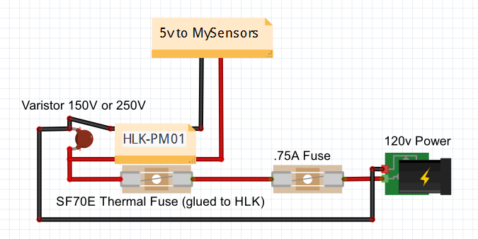
The wiring is easy to describe.
Put a fuse in line between the "hot" mains AC input and the power supply module input (the "neutral" can go directly to the power supply). Put a MOV across the power supply input (on the PS side of the fuse).
For small spikes, the MOV would protect the PS by absorbing most of it. For longer surges, the MOV would cause the fuse to blow, probably sacrificing itself in the process.
Maybe others can help with component selection (for 120v and 240v mains). I see that in the case of Littelfuse, the fuse is rated by RMS AC voltage, so a 140v MOV would work for a nominal 120VAC mains). http://www.littelfuse.com/~/media/electronics_technical/application_notes/varistors/littelfuse_selecting_a_littelfuse_varistor_application_note.pdf
I don't know if RMS rating is standard, or if some are rated by their DC voltage conduction threshold, but one would want to be sure of that for the brand they are getting.
@Zeph Thanks.
Do you all think a 150v MOV is ok for USA? I found some cheaper than the 140v on ebay but I' like to do it right :)
I found these fuses but they are 250v. Do you think that would be OK for 120v normal power or do I need to find 150v fuses?
Something like this for the temperature fuse?
http://www.ebay.com/itm/3-pcs-New-KSD-9700-70-C-250V-5A-Thermostat-Temperature-BiMetal-Switch-NC-Close-/141752004726?hash=item210113f076Is there anything else I'm missing that should be included in the circuit? Like others, I was also thinking that adding a temp sensor to the Arduino would be good so I could tell how hot it is in the box at any time.
-
More from the 'guru'
"There is no input fuse, that is the reason I recommend one and it has to be a real fuse that blows, not a fuse that will automatic recover. The only time it is supposed to blow is if the converter blows and then you want the mains permanently disconnected. Probably a 0.2A slow fuse will work."
@rvendrame Thanks for the clarification.
-
And a 250VAC fuse is fine to use on 120VAC (and in fact quite common).
-
Ok, how does this look for parts?
70 degree (Celsius) fuses - http://www.ebay.com/itm/10pcs-Thermal-Cutoffs-SEFUSE-Microtemp-Thermal-TF-Cutoff-NEC-Fuses-73-C-240-C-/221560426284?var=&hash=item339607cf2c
.75A fuse - They are fast blow not slow like specified above. Does that matter?? http://www.ebay.com/itm/40Pcs-ELECTRIC-FUSE-FAST-BLOW-0-75A-250VAC-35A-IR-THROUGH-HOLE-/271902224922?hash=item3f4ea2b21a
Is there anything else I'm missing? The goal with all this is to make another "how to" video so I want to make sure I'm not giving people bad advice.
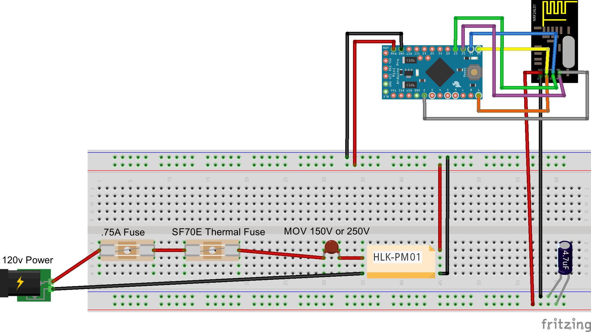
So, it would look something like this (ignore power to radio, didn't have time to wire it):
-
@rvendrame said:
@petewill . the MOV goes in parallel with HLK input (and not in series like you did).
It was suggested to use .2A fuses (instead the .75A). And the Thermal fuse should be glued on HLK top (my guess).
Dang, totally forgot about all that in my rush to finish the diagram before lunch ended... That's why you guys design the electronics and I make the videos ;)
How necessary are the .2A fuses? I couldn't find any on ebay at a reasonable price. Is the goal of this fuse to prevent large surges (like lightning) from hitting the MOV, or something else? If it's to prevent large surges would the .75A work ok?
Also, I was able to find cheaper varistors. I'm thinking 150VAC should work ok because the HLK is designed to handle 240VAC but maybe I'm off on that?
http://www.ebay.com/itm/5-x-Zinc-Oxide-Varistor-150VAC-15J-1200A-7mm-FREE-SHIPPING-/321024816822?hash=item4abe91f6b6How does this look?
@petewill said:
Also, I was able to find cheaper varistors. I'm thinking 150VAC should work ok because the HLK is designed to handle 240VAC but maybe I'm off on that?
As long as you only feed it with 120VAC, there's no issue with that. For those that will feed it with 240VAC, they need to use it with a MOV rated above that.
Cheers
AlPS Here's an option from Digikey: http://www.digikey.com/product-detail/en/MOV-10D241K/MOV-10D241K-ND/2407562
-
@rvendrame said:
@petewill . the MOV goes in parallel with HLK input (and not in series like you did).
It was suggested to use .2A fuses (instead the .75A). And the Thermal fuse should be glued on HLK top (my guess).
Dang, totally forgot about all that in my rush to finish the diagram before lunch ended... That's why you guys design the electronics and I make the videos ;)
How necessary are the .2A fuses? I couldn't find any on ebay at a reasonable price. Is the goal of this fuse to prevent large surges (like lightning) from hitting the MOV, or something else? If it's to prevent large surges would the .75A work ok?
Also, I was able to find cheaper varistors. I'm thinking 150VAC should work ok because the HLK is designed to handle 240VAC but maybe I'm off on that?
http://www.ebay.com/itm/5-x-Zinc-Oxide-Varistor-150VAC-15J-1200A-7mm-FREE-SHIPPING-/321024816822?hash=item4abe91f6b6How does this look?
@petewill said:
How necessary are the .2A fuses? I couldn't find any on ebay at a reasonable price. Is the goal of this fuse to prevent large surges (like lightning) from hitting the MOV, or something else? If it's to prevent large surges would the .75A work ok?
The fuse serves two purposes, one to protect if the current draw of the power supply exceeds its rated capacity and the other to blow if the varistor starts conducting a large amount of current in a spike situation. A .75A will still provide protection, but will take a longer time to blow. You want to make sure the fuse doesn't blow because of the in-rush current at start-up, which a fast-blow fuse may do. Typically you want the fuse to be sized at about 150% max of the rated capacity so I would not exceed .3A.
Cheers
Al -
@petewill said:
How necessary are the .2A fuses? I couldn't find any on ebay at a reasonable price. Is the goal of this fuse to prevent large surges (like lightning) from hitting the MOV, or something else? If it's to prevent large surges would the .75A work ok?
The fuse serves two purposes, one to protect if the current draw of the power supply exceeds its rated capacity and the other to blow if the varistor starts conducting a large amount of current in a spike situation. A .75A will still provide protection, but will take a longer time to blow. You want to make sure the fuse doesn't blow because of the in-rush current at start-up, which a fast-blow fuse may do. Typically you want the fuse to be sized at about 150% max of the rated capacity so I would not exceed .3A.
Cheers
AlAs long as you only feed it with 120VAC, there's no issue with that. For those that will feed it with 240VAC, they need to use it with a MOV rated above that.
I am in the USA so I will only be feeding it with 120VAC, but I will make sure to note that anyone using 240VAC will need a different value varistor.
the fuse should be after the varistor in the circuit
Ok, I'm still a little confused. Are you saying it should be 120VAC -> Varistor -> Fuse -> HLK? Or, 120VAC -> Fuse -> Varistor -> HLK? I thought it was the second one but maybe I misunderstood.
Also, I found some fuses that are rated at 300mA! Not a bad price either!
http://www.ebay.com/itm/Ceramic-Slow-Blow-Fuse-3-6-x-10mm-Axial-Leads-125V-250V-0-1A-6-3A-10-30pcs-/111433875797?var=&hash=item19f1fa0155I think I am almost ready to start ordering parts. I am excited for this build! If anyone else has any feedback please let me know. Thanks!
-
As long as you only feed it with 120VAC, there's no issue with that. For those that will feed it with 240VAC, they need to use it with a MOV rated above that.
I am in the USA so I will only be feeding it with 120VAC, but I will make sure to note that anyone using 240VAC will need a different value varistor.
the fuse should be after the varistor in the circuit
Ok, I'm still a little confused. Are you saying it should be 120VAC -> Varistor -> Fuse -> HLK? Or, 120VAC -> Fuse -> Varistor -> HLK? I thought it was the second one but maybe I misunderstood.
Also, I found some fuses that are rated at 300mA! Not a bad price either!
http://www.ebay.com/itm/Ceramic-Slow-Blow-Fuse-3-6-x-10mm-Axial-Leads-125V-250V-0-1A-6-3A-10-30pcs-/111433875797?var=&hash=item19f1fa0155I think I am almost ready to start ordering parts. I am excited for this build! If anyone else has any feedback please let me know. Thanks!
@petewill said:
the fuse should be after the varistor in the circuit
Ok, I'm still a little confused. Are you saying it should be 120VAC -> Varistor -> Fuse -> HLK? Or, 120VAC -> Fuse -> Varistor -> HLK? I thought it was the second one but maybe I misunderstood.
Sorry, the wording I used was unclear and was based on the 120VAC being on the right in your diagram :-). Yes, it is 120VAC -> Fuse -> Varistor -> HLK.
Cheers
Al -
@petewill said:
the fuse should be after the varistor in the circuit
Ok, I'm still a little confused. Are you saying it should be 120VAC -> Varistor -> Fuse -> HLK? Or, 120VAC -> Fuse -> Varistor -> HLK? I thought it was the second one but maybe I misunderstood.
Sorry, the wording I used was unclear and was based on the 120VAC being on the right in your diagram :-). Yes, it is 120VAC -> Fuse -> Varistor -> HLK.
Cheers
Al -
This one is not "safe", but it is an In-Wall AC to DC converter. Transformerless. With a 3A Solid state relay:
The converter output is 3.3V at 100mA and the solid state relay is a Triac.
@ceech said:
This one is not "safe", but it is an In-Wall AC to DC converter. Transformerless. With a 3A Solid state relay:
The converter output is 3.3V at 100mA and the solid state relay is a Triac.
Do you have some shcematic of this board ? I'd like to adapt it for 2 relays
Hello! It looks like you're interested in this conversation, but you don't have an account yet.
Getting fed up of having to scroll through the same posts each visit? When you register for an account, you'll always come back to exactly where you were before, and choose to be notified of new replies (either via email, or push notification). You'll also be able to save bookmarks and upvote posts to show your appreciation to other community members.
With your input, this post could be even better 💗
Register Login