ESP8266 WiFi gateway port for MySensors
-
I tried my Home Wifi and my Cell Hotspot. The crashes occur on both wifi networks. :-(
-
@Pseudomizer , Is the esp8266 on a breadboard or is it part of a commercial product like HUZZAH or nodemcu ? I ask because the esp devices can reset themselves from a brownout condition during the WiFi transmit if the power supply circuit is not up to handling the momentary 'high current draw' requirements of the radio. From reading www.esp8266.com, breadboard circuits have caused many hours of troubleshooting enjoyment with the esp8266 parts.
I replace the battery packs on these with 2 Amp cell phone charger power supplies. I have 8 under power 24/7 for months with no problems. They are available from multiple vendors.
http://www.aliexpress.com/item/Free-shipping-ESP8266-ESP-12-serial-WIFI-Industrial-stable-version-A-full-test-board-Full-IO/32260095422.html?spm=2114.01020208.3.49.0YGvDs&ws_ab_test=201556_7,201527_4_3_2_1_4_71_72_73_74_75,0_0 -
I followed the instructions exactly as shown here and I purchased that exact equipment.
http://www.mysensors.org/build/esp8266_gateway
I even powered the NRF24L01+ from a different power source just to make sure that power fluctuation is not the issue but it didn't make any difference.
I even tried transfer rates 115k, 57k and 9600 Baud but none of that made any difference either.
I also downloaded the flash eeprom ino program to clear all the data but again, no difference.
-
I even reflashed the ESP8266 with those instructions and then loaded the mysensors ino but still the same outcome. :-(
-
I even reflashed the ESP8266 with those instructions and then loaded the mysensors ino but still the same outcome. :-(
-
The only changes to the sketch are the SSID, the pass and the debug line
Serial.setDebugOutput(true);
as instructed. No other changes were made.
Here the the debug output....you will see multiple resets in a row based on the internal watchdog timer.
ESP8266 MySensors Gateway
Connecting to MYWIFI
scandone
f 0, scandone
.add 0
aid 1
pm open phy_2,type:2 0 0
cntconnected with MYWIFI, channel 6
dhcp client start...
......ip:192.168.1.222,mask:255.255.255.0,gw:192.168.1.1
.Connected!
IP: 192.168.1.222ets Jan 8 2013,rst cause:4, boot mode:(3,6)
wdt reset
load 0x4010f000, len 1264, room 16
tail 0
chksum 0x42
csum 0x42
~ldESP8266 MySensors Gateway
Connecting to MYWIFI
scandone
f 0, scandone
.add 0
aid 1
pm open phy_2,type:2 0 0
cntconnected with MYWIFI, channel 6
dhcp client start...
.......ip:192.168.1.222,mask:255.255.255.0,gw:192.168.1.1
.Connected!
IP: 192.168.1.222ets Jan 8 2013,rst cause:4, boot mode:(3,6)
wdt reset
load 0x4010f000, len 1264, room 16
tail 0
chksum 0x42
csum 0x42
~ldESP8266 MySensors Gateway
Connecting to MYWIFI
scandone
f 0, scandone
.add 0
aid 1
pm open phy_2,type:2 0 0
cntconnected with MYWIFI, channel 6
dhcp client start...
......ip:192.168.1.222,mask:255.255.255.0,gw:192.168.1.1
.Connected!
IP: 192.168.1.222 -
I just replaced the NRF with a new NRF and then again as I have 4 total. With every single one the same error.
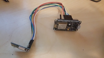
The wiring matches exactly the picture from mysensors.
This is driving me crazy...
-
Hi, I tried the bridge with a rfm69hw module. It starts all well but does not receive any information. Neither shows startup information module .
Where to put the DIO0 . I tried on several pins ( changing IRQ number) but no thoughts about doing anything. -
Hi, I tried the bridge with a rfm69hw module. It starts all well but does not receive any information. Neither shows startup information module .
Where to put the DIO0 . I tried on several pins ( changing IRQ number) but no thoughts about doing anything.@miguelingles I didn't test with a rfm69hw module and I'm not aware of anybody else testing with this setup.
Probably you have to test step by step what work and what not.
Start with the radio initialization to see if the communication is ok, and go on from there. -
I just replaced the NRF with a new NRF and then again as I have 4 total. With every single one the same error.
The wiring matches exactly the picture from mysensors.
This is driving me crazy...
@Pseudomizer past few days @hek and I have been working on better diagnosis for the ESP8266 regarding radio communication failures.
Please try if the version of MySensors development helps in diagnosing your problems.
Make sure to uncomment the line//#define MY_DEBUG_VERBOSEin MyConfig.h and make the same changes to ssid & password as you did before.
This version will dump diagnostics of NRF communications and a full register dump when starting up.
Good luck! -
Thanks a lot. This version provides much more details but at this stage of my learning progress I am not able to understand all those registers where I have to rely on your help guys. I assume that my password is not being exposed here.
ESP8266 MySensors Gateway
Connecting to ZEUS
scandone
f 0, scandone
.add 0
aid 1
pm open phy_2,type:2 0 0
cntconnected with ZEUS, channel 6
dhcp client start...
......ip:192.168.1.222,mask:255.255.255.0,gw:192.168.1.1
.Connected!
IP: 192.168.1.222
write_register(0x04,0x5F)
write_register(0x06,0x23)
write_register(0x06,0x03)
write_register(0x00,0x0E)
write_register(0x07,0x70)
write_register(0x05,0x4C)
write_register(0x00,0x0E)
STATUS 0x0E RX_DR=0 TX_DS=0 MAX_RT=0 RX_P_NO=7 TX_FULL=0
RX_ADDR_P0-1 0x0E0E0E0E0E 0707070707
RX_ADDR_P2-5 0xFF C4 C5 C6
TX_ADDR 0x0E0E0E0E0E
RX_PW_P0-6 0x00 00 20 00 00 00
EN_AA 0x3B
EN_RXADDR 0x07
RF_CH 0x4C
RF_SETUP 0x03
CONFIG 0x0E
DYNPD/FEATURE 0x3F 06
Data Rate 1MBPS
Model nRF24L01+
CRC Length 16 bits
PA Power PA_LOW
write_register(0x01,0x3F)
write_register(0x01,0x3B)
write_register(0x1D,0x06)
FEATURE=0x06
write_register(0x1C,0x3F)
write_register(0x05,0x4C)
write_register(0x06,0x0
ets Jan 8 2013,rst cause:4, boot mode:(3,7)wdt reset
load 0x4010f000, len 1264, room 16
tail 0
chksum 0x42
csum 0x42
~ldESP8266 MySensors Gateway
Connecting to ZEUS
scandone
f 0, scandone
.add 0
aid 1
pm open phy_2,type:2 0 0
cntconnected with ZEUS, channel 6
dhcp client start...
......ip:192.168.1.222,mask:255.255.255.0,gw:192.168.1.1
.Connected!
IP: 192.168.1.222
write_register(0x04,0x5F)
write_register(0x06,0x23)
write_register(0x06,0x03)
write_register(0x00,0x0E)
write_register(0x07,0x70)
write_register(0x05,0x4C)
write_register(0x00,0x0E)
STATUS 0x0E RX_DR=0 TX_DS=0 MAX_RT=0 RX_P_NO=7 TX_FULL=0
RX_ADDR_P0-1 0x0E0E0E0E0E 0707070707
RX_ADDR_P2-5 0xFF C4 C5 C6
TX_ADDR 0x0E0E0E0E0E
RX_PW_P0-6 0x00 00 20 00 00 00
EN_AA 0x3B
EN_RXADDR 0x07
RF_CH 0x4C
RF_SETUP 0x03
CONFIG 0x0E
DYNPD/FEATURE 0x3F 06
Data Rate 1MBPS
Model nRF24L01+
CRC Length 16 bits
PA Power PA_LOW
write_register(0x01,0x3F)
write_register(0x01,0x3B)
write_register(0x1D,0x06)
FEATURE=0x06
write_register(0x1C,0x3F)
write_register(0x05,0x4C)
write_register(0x06,0x0
ets Jan 8 2013,rst cause:4, boot mode:(3,7)wdt reset
load 0x4010f000, len 1264, room 16
tail 0
chksum 0x42
csum 0x42
~ld -
when I put the development package I can not compile anything (all gives me error). I tried it with a clean install and nothing.
I think the problem is the IRQ pin DIØØ , if the ESP cpu does not recognize this interruption when the RF module receives data is unable to apply for the request . -
when I put the development package I can not compile anything (all gives me error). I tried it with a clean install and nothing.
I think the problem is the IRQ pin DIØØ , if the ESP cpu does not recognize this interruption when the RF module receives data is unable to apply for the request .@miguelingles said:
I think the problem is the IRQ pin DIØØ , if the ESP cpu does not recognize this interruption when the RF module receives data is unable to apply for the request .
The irq pin from the nrf24 stays unconnected, like the build instructions clearly state!
-
but RF69 need irq.
-
but RF69 need irq.
-
The only changes to the sketch are the SSID, the pass and the debug line
Serial.setDebugOutput(true);
as instructed. No other changes were made.
Here the the debug output....you will see multiple resets in a row based on the internal watchdog timer.
ESP8266 MySensors Gateway
Connecting to MYWIFI
scandone
f 0, scandone
.add 0
aid 1
pm open phy_2,type:2 0 0
cntconnected with MYWIFI, channel 6
dhcp client start...
......ip:192.168.1.222,mask:255.255.255.0,gw:192.168.1.1
.Connected!
IP: 192.168.1.222ets Jan 8 2013,rst cause:4, boot mode:(3,6)
wdt reset
load 0x4010f000, len 1264, room 16
tail 0
chksum 0x42
csum 0x42
~ldESP8266 MySensors Gateway
Connecting to MYWIFI
scandone
f 0, scandone
.add 0
aid 1
pm open phy_2,type:2 0 0
cntconnected with MYWIFI, channel 6
dhcp client start...
.......ip:192.168.1.222,mask:255.255.255.0,gw:192.168.1.1
.Connected!
IP: 192.168.1.222ets Jan 8 2013,rst cause:4, boot mode:(3,6)
wdt reset
load 0x4010f000, len 1264, room 16
tail 0
chksum 0x42
csum 0x42
~ldESP8266 MySensors Gateway
Connecting to MYWIFI
scandone
f 0, scandone
.add 0
aid 1
pm open phy_2,type:2 0 0
cntconnected with MYWIFI, channel 6
dhcp client start...
......ip:192.168.1.222,mask:255.255.255.0,gw:192.168.1.1
.Connected!
IP: 192.168.1.222For everyone wondering what serial output during startup of the ESP8266-NRF24 gateway should look like (all captures taken using link development branch from Oct 6, 2015 (hek just merged gateway-refactoring this morning, so output might have slightly changed)) .
WiFi startup comes first after reset, followed by MySensors (nRF24) startup:
- WiFi startup (not using Serial.setDebugOutput(true) )
ESP8266 MySensors Gateway Connecting to YOUR_SSID ...........Connected! IP: 192.168.1.101- WiFi startup (using Serial.setDebugOutput(true) )
ESP8266 MySensors Gateway Connecting to YOUR_SSID scandone f 0, ....scandone .add 0 aid 10 pm open phy_2,type:2 0 0 cnt connected with YOUR_SSID, channel 1 dhcp client start... .....ip:192.168.1.101,mask:255.255.255.0,gw:192.168.1.1 .Connected! IP: 192.168.1.101- MySensors startup (not using DEBUG and MY_DEBUG_VERBOSE)
0;0;3;0;9;gateway started, id=0, parent=0, distance=0- MySensors startup (using DEBUG and MY_DEBUG_VERBOSE)
write_register(0x04,0x5F) write_register(0x06,0x27) write_register(0x06,0x07) write_register(0x00,0x0C) write_register(0x07,0x70) write_register(0x05,0x4C) write_register(0x00,0x0E) write_register(0x00,0x0E) STATUS 0x0E RX_DR=0 TX_DS=0 MAX_RT=0 RX_P_NO=7 TX_FULL=0 RX_ADDR_P0-1 0x0E0E0E0E0E 0303030303 RX_ADDR_P2-5 0xC3 C4 C5 C6 TX_ADDR 0x0E0E0E0E0E RX_PW_P0-6 0x00 00 00 00 00 00 EN_AA 0x3F EN_RXADDR 0x03 RF_CH 0x4C RF_SETUP 0x07 CONFIG 0x0E DYNPD/FEATURE 0x00 00 Data Rate 1MBPS Model nRF24L01+ CRC Length 16 bits PA Power PA_MAX write_register(0x01,0x3F) write_register(0x01,0x3B) write_register(0x1D,0x06) FEATURE=0x06 write_register(0x1C,0x03) write_register(0x05,0x4C) write_register(0x06,0x03) write_register(0x06,0x23) write_register(0x04,0x5F) write_register(0x00,0x0E) write_register(0x1D,0x06) FEATURE=0x06 write_register(0x1C,0x3F) write_register(0x13,0x20) write_register(0x02,0x07) write_register(0x11,0x20) write_register(0x02,0x07) write_register(0x12,0x20) write_register(0x02,0x07) write_register(0x00,0x0F) write_register(0x07,0x70) write_register(0x02,0x06) 0;0;3;0;9;gateway started, id=0, parent=0, distance=0 -
Thanks a lot. This version provides much more details but at this stage of my learning progress I am not able to understand all those registers where I have to rely on your help guys. I assume that my password is not being exposed here.
ESP8266 MySensors Gateway
Connecting to ZEUS
scandone
f 0, scandone
.add 0
aid 1
pm open phy_2,type:2 0 0
cntconnected with ZEUS, channel 6
dhcp client start...
......ip:192.168.1.222,mask:255.255.255.0,gw:192.168.1.1
.Connected!
IP: 192.168.1.222
write_register(0x04,0x5F)
write_register(0x06,0x23)
write_register(0x06,0x03)
write_register(0x00,0x0E)
write_register(0x07,0x70)
write_register(0x05,0x4C)
write_register(0x00,0x0E)
STATUS 0x0E RX_DR=0 TX_DS=0 MAX_RT=0 RX_P_NO=7 TX_FULL=0
RX_ADDR_P0-1 0x0E0E0E0E0E 0707070707
RX_ADDR_P2-5 0xFF C4 C5 C6
TX_ADDR 0x0E0E0E0E0E
RX_PW_P0-6 0x00 00 20 00 00 00
EN_AA 0x3B
EN_RXADDR 0x07
RF_CH 0x4C
RF_SETUP 0x03
CONFIG 0x0E
DYNPD/FEATURE 0x3F 06
Data Rate 1MBPS
Model nRF24L01+
CRC Length 16 bits
PA Power PA_LOW
write_register(0x01,0x3F)
write_register(0x01,0x3B)
write_register(0x1D,0x06)
FEATURE=0x06
write_register(0x1C,0x3F)
write_register(0x05,0x4C)
write_register(0x06,0x0
ets Jan 8 2013,rst cause:4, boot mode:(3,7)wdt reset
load 0x4010f000, len 1264, room 16
tail 0
chksum 0x42
csum 0x42
~ldESP8266 MySensors Gateway
Connecting to ZEUS
scandone
f 0, scandone
.add 0
aid 1
pm open phy_2,type:2 0 0
cntconnected with ZEUS, channel 6
dhcp client start...
......ip:192.168.1.222,mask:255.255.255.0,gw:192.168.1.1
.Connected!
IP: 192.168.1.222
write_register(0x04,0x5F)
write_register(0x06,0x23)
write_register(0x06,0x03)
write_register(0x00,0x0E)
write_register(0x07,0x70)
write_register(0x05,0x4C)
write_register(0x00,0x0E)
STATUS 0x0E RX_DR=0 TX_DS=0 MAX_RT=0 RX_P_NO=7 TX_FULL=0
RX_ADDR_P0-1 0x0E0E0E0E0E 0707070707
RX_ADDR_P2-5 0xFF C4 C5 C6
TX_ADDR 0x0E0E0E0E0E
RX_PW_P0-6 0x00 00 20 00 00 00
EN_AA 0x3B
EN_RXADDR 0x07
RF_CH 0x4C
RF_SETUP 0x03
CONFIG 0x0E
DYNPD/FEATURE 0x3F 06
Data Rate 1MBPS
Model nRF24L01+
CRC Length 16 bits
PA Power PA_LOW
write_register(0x01,0x3F)
write_register(0x01,0x3B)
write_register(0x1D,0x06)
FEATURE=0x06
write_register(0x1C,0x3F)
write_register(0x05,0x4C)
write_register(0x06,0x0
ets Jan 8 2013,rst cause:4, boot mode:(3,7)wdt reset
load 0x4010f000, len 1264, room 16
tail 0
chksum 0x42
csum 0x42
~ld@Pseudomizer Had a better look at your crashdump.
Your ESP seems to crash with a watchdog timeout when MySensors is setting the datarate (or shortly after that) after nRF24 has been initialized.
Default datarate is RF24_250KBPS.Some questions, trying to rule things out:
- Do you use this default datarate?
- Could it be that you have an nRF24L01+ clone, which in reality is a nRF24L01 (clone)?
- Did you ever try and succeed to connect these radios to a regular Arduino?
- Are all radio's from the same batch/order?
Hello! It looks like you're interested in this conversation, but you don't have an account yet.
Getting fed up of having to scroll through the same posts each visit? When you register for an account, you'll always come back to exactly where you were before, and choose to be notified of new replies (either via email, or push notification). You'll also be able to save bookmarks and upvote posts to show your appreciation to other community members.
With your input, this post could be even better 💗
Register Login