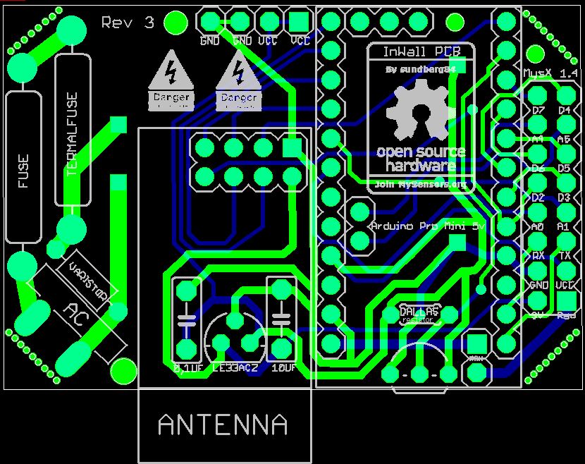
In wall - PCB, (AC to DC 5v)
-
The test I did was just to strip a extension cord, attach "the fuse" to it and apply different equipment with spec from 5W up to my vaccumcl 1000+W Not proffessional but I dont have any other equipment.
I dont think we changed the placement? I made a misstake in my first rev but now my varistor placement is like your post (after both fuse and termal fuse). But @m26872 link describes it good why.
@samuel235 Good luck with your board! Do not take my board as "thats how it should be". My board is the result and my interpretation of the discussions so far in this forum. If that is right or wrong i not able to tell (yet). The tempsensor is to initially be able to measure the temp in that closed box to see that the node doesnt produce to much heat.
Im glad you are creating your own... as i said before, my wish is that we all come together and in the end create a small and safe in wall PCB. And If you want (and use Eagles) ill send over the files for the PCB. I will also post them here when i recieved the boards offcourse.
Here is my bitmap I use as a logo... in eagles you can import that to layer 21 and apply to your board.

Awesome, yes if you could send me the eagle files I would really appreciate that to allow me to learn how this circuit is working. I completely understand that this is just your interpritation on how it should work. I'm using this as a kind of reference i suppose, just to learn how this is wired out, whats connected in what order etc etc. I will not take this as a 'only way to get ac power to arduino on one board' type of application, don't worry ;)
Thank you for the BMP Image, i will add the MySensors logo to the board too along side of this logo.
The parts for my board have just arrived as I was replying to this. Just waiting on the boards to come from ITead now. Time to get moving!
I have a weird feeling that 2016 will be huge for MySensors and its community!
-
@sundberg84 Thanks for the picture. It's totally different than mine. You said you got it from the same store I linked to in the "Safe in-wall" post? This is what mine looks like:
I will still test it with to be sure but I'm reassured that it at least looks different.
I dont think we changed the placement?
Sorry, you're right, my mistake. I misread/misunderstood the issue as I was reading through this thread. It was still helpful to read @m26872's link though, thanks for that!
-
The test I did was just to strip a extension cord, attach "the fuse" to it and apply different equipment with spec from 5W up to my vaccumcl 1000+W Not proffessional but I dont have any other equipment.
I dont think we changed the placement? I made a misstake in my first rev but now my varistor placement is like your post (after both fuse and termal fuse). But @m26872 link describes it good why.
@samuel235 Good luck with your board! Do not take my board as "thats how it should be". My board is the result and my interpretation of the discussions so far in this forum. If that is right or wrong i not able to tell (yet). The tempsensor is to initially be able to measure the temp in that closed box to see that the node doesnt produce to much heat.
Im glad you are creating your own... as i said before, my wish is that we all come together and in the end create a small and safe in wall PCB. And If you want (and use Eagles) ill send over the files for the PCB. I will also post them here when i recieved the boards offcourse.
Here is my bitmap I use as a logo... in eagles you can import that to layer 21 and apply to your board.
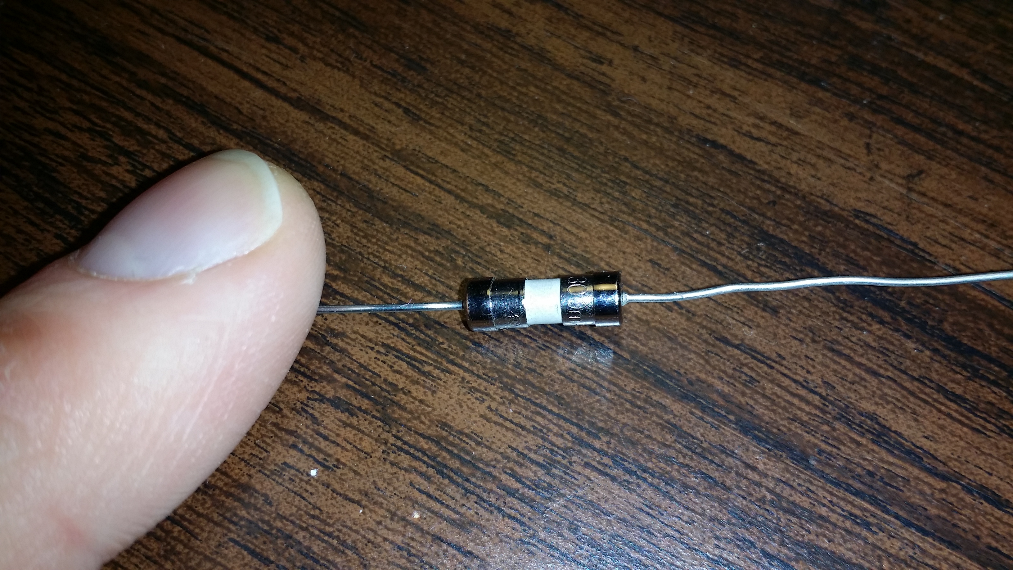
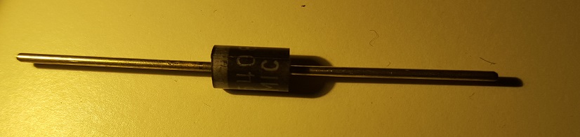
@sundberg84 Your 'fuse' looks very much like a regular diode, e.g. 1N4007:
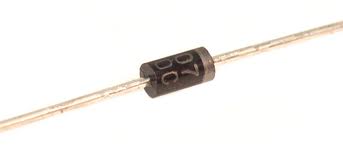
You can easily verify by using a multimeter, or even the printing on the component could reveal its real identity.
Some sellers ship both clothes and electronic components, so maybe the seller just shipped the wrong parts? -
@Yveaux Yea, could be - its not a 1n4007 because i have those as well, and also it conducts in two ways. Anyway, you are probably right - they shipped the wrong item. @petewill I ordered from the link in safe-in-wall thread: http://www.ebay.com/itm/111433875797?_trksid=p2057872.m2749.l2649&ssPageName=STRK%3AMEBIDX%3AIT&rmvSB=true
-
I finally had a spare minute to test my fuse. Good news, it worked! I plugged in a 13 watt florescent light bulb and it turned on. I then plugged in a 32 Watt florescent light bulb and it blew the fuse. @sundberg84 sorry you got the wrong ones! Hopefully other people who ordered got the ones that I did.
-
This post is archived!
Please use this thread to post questions:https://forum.mysensors.org/topic/2783/in-wall-ac-dc-pcb-for-mysensors
Project can be found here:
https://www.openhardware.io/view/13/In-Wall-ACDC-Pcb-for-MySensors
Hi!
As i mentioned in another post i had this idea to stack two PCB on top of each other to fit inside a wall appliance box. This idea has evolved (see below).
Im aware of the big security risk here, and have tried to read:
- http://forum.mysensors.org/topic/1607/safe-in-wall-ac-to-dc-transformers
- http://forum.mysensors.org/topic/1540/110v-230v-ac-to-mysensors-pcb-board
EDIT 03/1/2016
After discussion on this here are the findings of this thread (as of now):I will update this post with BOM and eagles files as soon as i get a node running.
...............................
BOM/README: http://1drv.ms/1kCzue5
GERBER: InWallMySensor3.0.rar
EAGLES: InWallMySensor3.0Eagles.rar
Build images: http://1drv.ms/1lsleox
...............................If you are using this design, please know about the risks when you work with high power. This design has no guarantee s so use it on your own risk!
@sundberg84, gr8 job done....really amazing to see this one. i want to make few sensors for my home. Is the design of the board is final? Kindly guide me for the placement of LE33 and Dallas Temp as mentioned in your BOM that placement "solder Le33 + Caps (1,0, 10uf) on the pcb underside. Note the directions of the LE33 (not as silk mask!)"
Also, will it be possible for you to upload the design to http://dirtypcbs.com, as i don't have any knowledge about PCB manufacturing. it will be very easy for me to order and get the PCBs for assembly.
I am very new to all this and learning from you guys.....
Thanks
Brijesh -
@Brijesh-Mishra Thank you! Im waiting for Rev3 to arrive. It was manufactured a week ago so i guess it will arrive on 1-2 weeks. I will post and let you know the status here.
I will also update the BOM with better instructions. LE33 should be soldered on the back side which reverse the direction of the pins (VCC/OUT). This means that the nice print on silkmask (white markings how the LE33 should be mounted) is not correct.
Its a nice idea at dirtypcb, I can do that i guess!
-
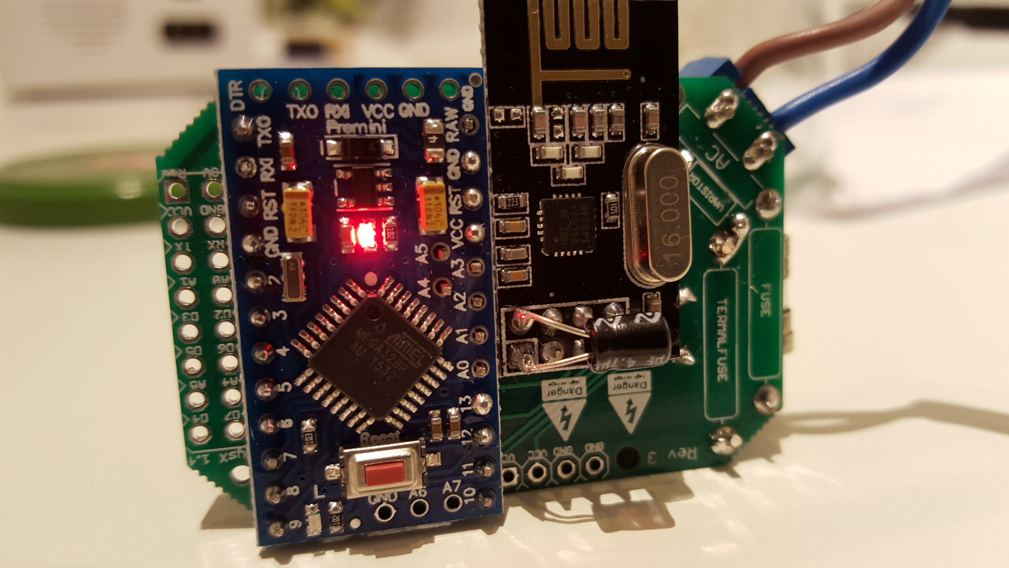
Rev 3 arrived today and its working, nice.
I soldered it togheter and uploaded a dallas temp sketch and ran it with AC power.Next step is a long time test in a small space, measuring temp.
Also it would be nice to get some tips how i can test it more... (safety check).Files and readme can be found in the first post.
Also this image for where i assemble the pcb (build).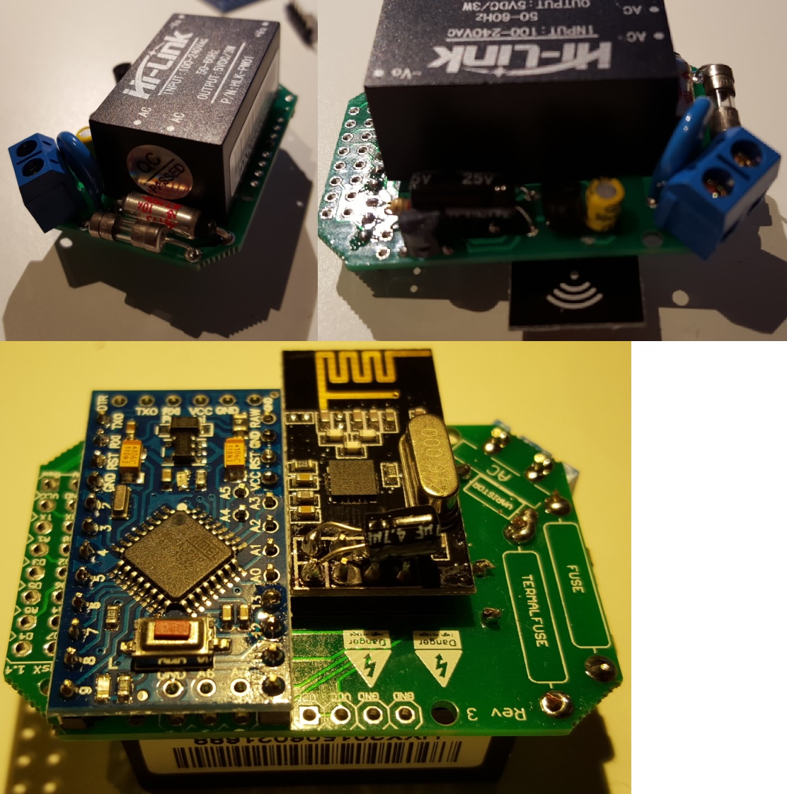
-
Rev 3 arrived today and its working, nice.
I soldered it togheter and uploaded a dallas temp sketch and ran it with AC power.Next step is a long time test in a small space, measuring temp.
Also it would be nice to get some tips how i can test it more... (safety check).Files and readme can be found in the first post.
Also this image for where i assemble the pcb (build).@sundberg84 This is awesome progress dude!
So in my honest opinion, from a professional tradesman plastering, tiling, stud walls, plaster boarding are my specialties, I would firstly test this inside of a back-box, outside of a wall with the front attached (like it would be in a real-life situation). Then once that passes your expectations and requirements, I would then test it inside of a back-box located inside of a wall but without the front plate screwed on. Then once that passes, I would connect the front plate and manually monitor the temps inside of the controller.
If your question was aimed more towards how to test it electronically, then i'm sorry i can't help in that department, as you already know, I'm pretty weak at electronics at the moment still.
Its awesome to see your project coming on, very swiftly too. Keep up the good work!
-
@sundberg84 - Correct me If i'm being a complete NOOB here....
Your fuses, if they are the same function as what i feel to be a 'general household fuse', could you not use a removable fuse in a holder. This way if a fuse blows/trips all you would need to do is change out the fuse. This is all depending on what caused the fuse to blow, if it was an environment issue (spike of power draw, etc) then you could just change the fuse and power back up... Rather than having to get the soldering iron out.
Again, If I have incorrectly understood the principle of the fuse in this application, please notify me.
-
@samuel235 You are right - the only problem is size.
If you find a removable fuse as small as this axial fuse please let me know!
Most are 2x20mm and the holder are bigger. -
So today I have been testing temperatures inside a closed compartment with my PCB.
I drilled a hole in a metal cap to a glass bottle, put AC main through the metal cap and wrapped everything up inside. I then found some insulation material and wrapped the glas bottle up.- First test was only minimum components and sleep for two minutes.
- Second test was the same but i added a LCD screen on maximum background lights and also a relay which switched on and off every 2 minutes sleep cycle.
- Third test was to remove the sleep and used wait instead so the node was powered all the time.
No problems so far, max temp during last test was 34,8 dgr C. Here is my numbers:
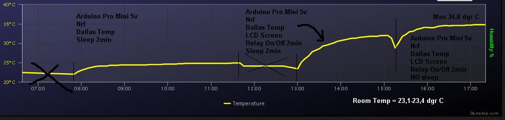
Any other ideas or components i can use to try - write a post!
-- Next
So... there are some (important) questions ahead i dont know how to answer though...
- Reliability, when will it fail? (compared to a commersial product?)
- How will it fail? What is it weakest point?
- Will my safety components be enough and prevail damage... ?
- What will happen when it fails?
Anyone having thoughts... let me know.
-
@samuel235 You are right - the only problem is size.
If you find a removable fuse as small as this axial fuse please let me know!
Most are 2x20mm and the holder are bigger.@sundberg84 said:
@samuel235 You are right - the only problem is size.
Ahh okay, indeed you're right. However, what is going on the front of the in wall box? Is it still being mounted inside of a wall box, or are you have it concealed away behind the wall where you can't really get to it easily? It isn't behind a light switch/socket?
-
@samuel235 depend on what you wants to do with it - its dynamic since you have the pins. If you want to add a relay and button you can hide it in the wallbox and still have the physical button or in the ceiling if you dont need that.
-
@samuel235 depend on what you wants to do with it - its dynamic since you have the pins. If you want to add a relay and button you can hide it in the wallbox and still have the physical button or in the ceiling if you dont need that.
@sundberg84 - So It Is essentially a 'multi-use backboard' kind of application. So what I was trying to get to - In the UK we have something called a fused switch (link to image below). Now, you see that little rectangle to the side of the switch, its a fuse inside of a holder. I'm wondering if a possible model for a switch plate like that or any front plate to suit the needs (screen, switch, motion sensor, etc) could be maybe 3d printed, with that fuse holder incorporated into the front late with the board that you have made attached to the back of the front plate in such a manor that you can swap the fuse out without dismantling the whole socket or even soldering. Just a suggestion, well a huge suggestion at that i suppose.
-
Im getting quite bad radio performance when i seal this inside some boxes... works much better if I dont have the lid on.
Does anyone know if the HLK can interfere with the radio (magnetic fields or anything)? EMF?
Power supply to radio has both 0.1 and 10 caps so I dont hope its spikes or power to radio thats bad.Maybe I should move the radio away from AC side?
@sundberg84 Connect a battery supply instead of the LE33 and see if it helps?
-
@m26872 Yea, could try that one - nice thinking.
Made a testnode to see some performance on my PCB.
Combined temp, hum (DHT), motion and light sensor.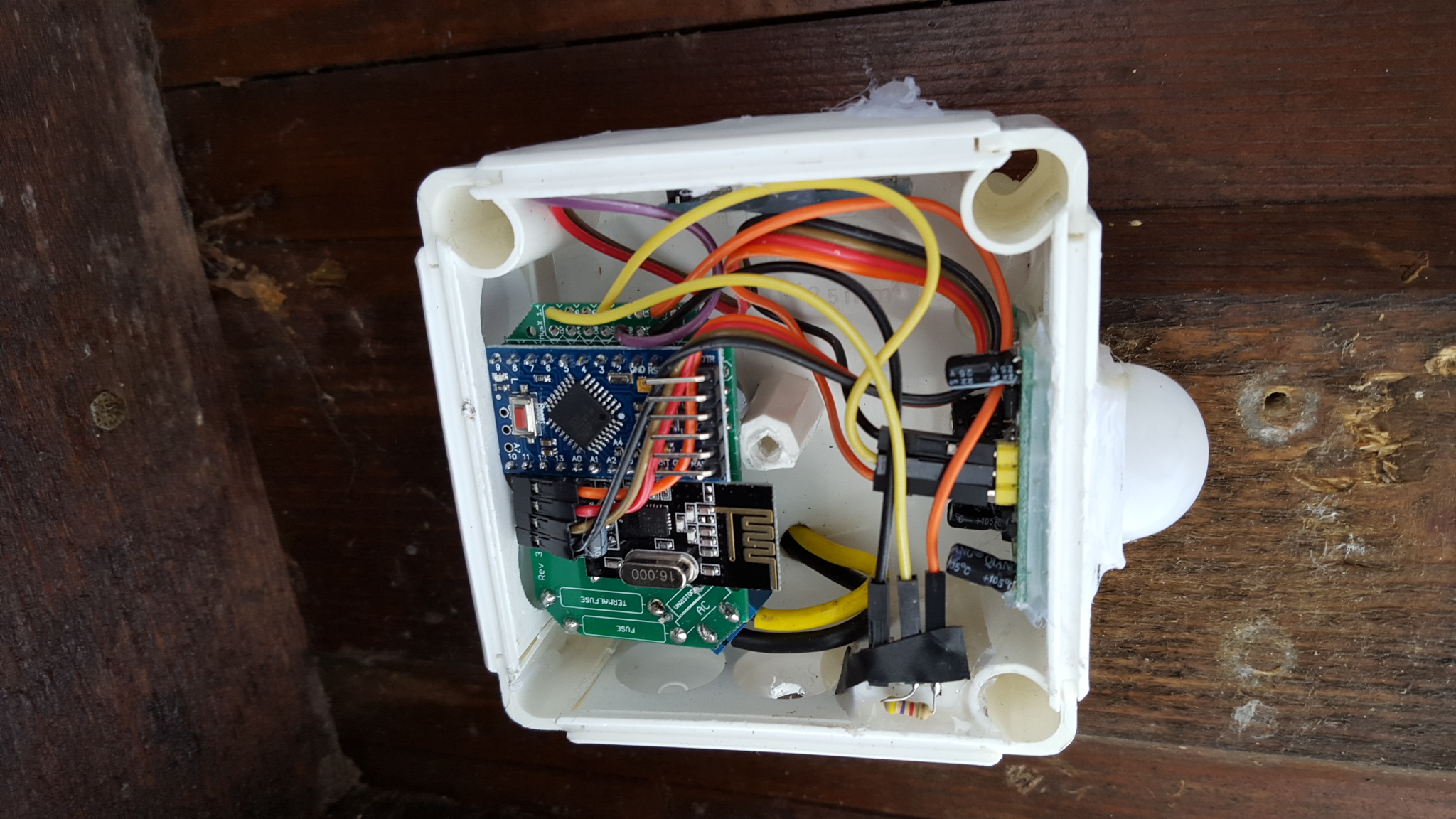
Sometimes i forget to think before i build though... not smart to measure temp and put it besides a power supply that generates heat, doh!
-
Trying to take this to the next level:
3d design - first try (ever!).
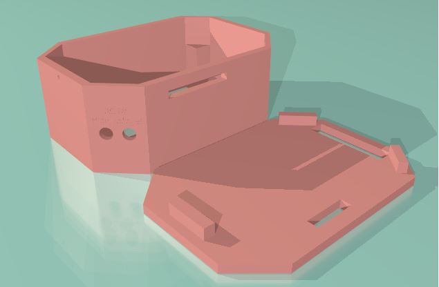
I guess it wont meet any standard since its not completley sealed up - but I want to be able to reach the MYSX connector. Might be OK if I use a female pin header to MysX connector, then it wont be possible to put your finger inside.
-
So, just a small update - im waiting for new PCB and parts (going to SMD components), almost everything has arrived but some nessecary things still missing.
I will leave this project here but not develop this version any more.
Instead I will create a new thread with the new SMD version!
Hello! It looks like you're interested in this conversation, but you don't have an account yet.
Getting fed up of having to scroll through the same posts each visit? When you register for an account, you'll always come back to exactly where you were before, and choose to be notified of new replies (either via email, or push notification). You'll also be able to save bookmarks and upvote posts to show your appreciation to other community members.
With your input, this post could be even better 💗
Register Login