Slim Node Si7021 sensor example
-
@m26872 I have built the Slim Node described above and i am using your exact sketch given above but when i look at the serial monitor, it is printing junk characters i tried different baud rates on the serial monitor but nothing works.
I am connected to the slim node using FTDI board.
Any thoughts?
Thanks for your help.
-
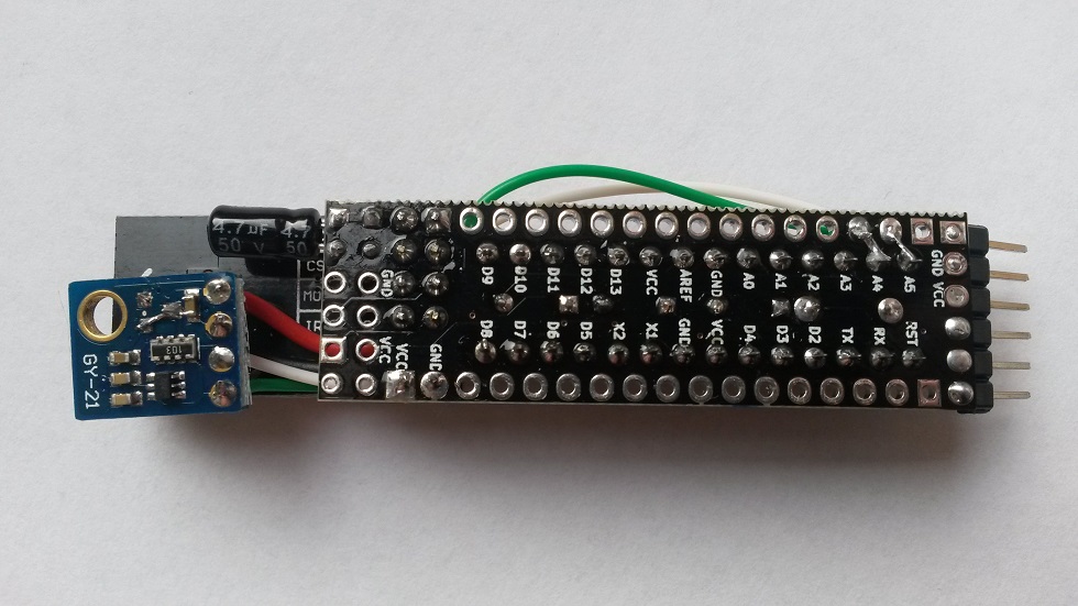
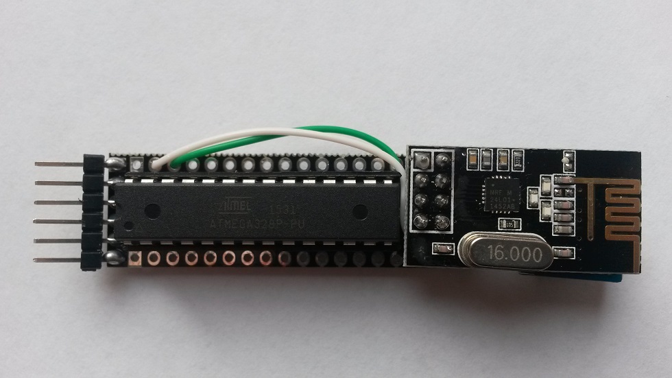
I've tried to post some sensor examples in the main Slim Node thread. It's continuously growing and I think it's better to start new threads for as much as possible. Here's one. I used this Si7021 (GY-21 board).
Sketch
Apologize for still not having cleaned up the sketch yet .../* Sketch with Si7021 and battery monitoring. by m26872, 20151109 */ #include <MySensor.h> #include <Wire.h> #include <SI7021.h> #include <SPI.h> #include <RunningAverage.h> //#define DEBUG #ifdef DEBUG #define DEBUG_SERIAL(x) Serial.begin(x) #define DEBUG_PRINT(x) Serial.print(x) #define DEBUG_PRINTLN(x) Serial.println(x) #else #define DEBUG_SERIAL(x) #define DEBUG_PRINT(x) #define DEBUG_PRINTLN(x) #endif #define NODE_ID 132 // <<<<<<<<<<<<<<<<<<<<<<<<<<< Enter Node_ID #define CHILD_ID_TEMP 0 #define CHILD_ID_HUM 1 // #define SLEEP_TIME 15000 // 15s for DEBUG #define SLEEP_TIME 300000 // 5 min #define FORCE_TRANSMIT_CYCLE 36 // 5min*12=1/hour, 5min*36=1/3hour #define BATTERY_REPORT_CYCLE 2880 // Once per 5min => 12*24*7 = 2016 (one report/week) #define VMIN 1900 #define VMAX 3300 #define HUMI_TRANSMIT_THRESHOLD 3.0 // THRESHOLD tells how much the value should have changed since last time it was transmitted. #define TEMP_TRANSMIT_THRESHOLD 0.5 #define AVERAGES 2 int batteryReportCounter = BATTERY_REPORT_CYCLE - 1; // to make it report the first time. int measureCount = 0; float lastTemperature = -100; int lastHumidity = -100; RunningAverage raHum(AVERAGES); SI7021 humiditySensor; MySensor gw; MyMessage msgTemp(CHILD_ID_TEMP,V_TEMP); // Initialize temperature message MyMessage msgHum(CHILD_ID_HUM,V_HUM); void setup() { DEBUG_SERIAL(115200); // <<<<<<<<<<<<<<<<<<<<<<<<<< Note BAUD_RATE in MySensors.h DEBUG_PRINTLN("Serial started"); DEBUG_PRINT("Voltage: "); DEBUG_PRINT(readVcc()); DEBUG_PRINTLN(" mV"); /* delay(500); DEBUG_PRINT("Internal temp: "); DEBUG_PRINT(GetInternalTemp()); // Probably not calibrated. Just to print something. DEBUG_PRINTLN(" *C"); */ delay(500); // Allow time for radio if power useed as reset gw.begin(NULL,NODE_ID); gw.sendSketchInfo("EgTmpHumBat5min", "1.0 151106"); gw.present(CHILD_ID_TEMP, S_TEMP); // Present sensor to controller gw.present(CHILD_ID_HUM, S_HUM); DEBUG_PRINT("Node and "); DEBUG_PRINTLN("2 children presented."); raHum.clear(); } void loop() { measureCount ++; batteryReportCounter ++; bool forceTransmit = false; if (measureCount > FORCE_TRANSMIT_CYCLE) { forceTransmit = true; } sendTempHumidityMeasurements(forceTransmit); /* // Read and print internal temp float temperature0 = static_cast<float>(static_cast<int>((GetInternalTemp()+0.5) * 10.)) / 10.; DEBUG_PRINT("Internal Temp: "); DEBUG_PRINT(temperature0); DEBUG_PRINTLN(" *C"); */ // Check battery if (batteryReportCounter >= BATTERY_REPORT_CYCLE) { long batteryVolt = readVcc(); DEBUG_PRINT("Battery voltage: "); DEBUG_PRINT(batteryVolt); DEBUG_PRINTLN(" mV"); uint8_t batteryPcnt = constrain(map(batteryVolt,VMIN,VMAX,0,100),0,255); DEBUG_PRINT("Battery percent: "); DEBUG_PRINT(batteryPcnt); DEBUG_PRINTLN(" %"); gw.sendBatteryLevel(batteryPcnt); batteryReportCounter = 0; } gw.sleep(SLEEP_TIME); } // function for reading Vcc by reading 1.1V reference against AVcc. Based from http://provideyourown.com/2012/secret-arduino-voltmeter-measure-battery-voltage/ // To calibrate reading replace 1125300L with scale_constant = internal1.1Ref * 1023 * 1000, where internal1.1Ref = 1.1 * Vcc1 (per voltmeter) / Vcc2 (per readVcc() function) long readVcc() { // set the reference to Vcc and the measurement to the internal 1.1V reference ADMUX = _BV(REFS0) | _BV(MUX3) | _BV(MUX2) | _BV(MUX1); delay(2); // Wait for Vref to settle ADCSRA |= _BV(ADSC); // Start conversion while (bit_is_set(ADCSRA,ADSC)); // measuring uint8_t low = ADCL; // must read ADCL first - it then locks ADCH uint8_t high = ADCH; // unlocks both long result = (high<<8) | low; result = 1125300L / result; // Calculate Vcc (in mV); 1125300 = 1.1*1023*1000 return result; // Vcc in millivolts } // function for reading internal temp. From http://playground.arduino.cc/Main/InternalTemperatureSensor double GetInternalTemp(void) { // (Both double and float are 4 byte in most arduino implementation) unsigned int wADC; double t; // The internal temperature has to be used with the internal reference of 1.1V. Channel 8 can not be selected with the analogRead function yet. ADMUX = (_BV(REFS1) | _BV(REFS0) | _BV(MUX3)); // Set the internal reference and mux. ADCSRA |= _BV(ADEN); // enable the ADC delay(20); // wait for voltages to become stable. ADCSRA |= _BV(ADSC); // Start the ADC while (bit_is_set(ADCSRA,ADSC)); // Detect end-of-conversion wADC = ADCW; // Reading register "ADCW" takes care of how to read ADCL and ADCH. t = (wADC - 88.0 ) / 1.0; // The default offset is 324.31. return (t); // The returned temperature in degrees Celcius. } /********************************************* * * Sends temperature and humidity from Si7021 sensor * Parameters * - force : Forces transmission of a value (even if it's the same as previous measurement) *********************************************/ void sendTempHumidityMeasurements(bool force) { bool tx = force; si7021_env data = humiditySensor.getHumidityAndTemperature(); float temperature = data.celsiusHundredths / 100.0; DEBUG_PRINT("T: ");DEBUG_PRINTLN(temperature); float diffTemp = abs(lastTemperature - temperature); DEBUG_PRINT(F("TempDiff :"));DEBUG_PRINTLN(diffTemp); if (diffTemp > TEMP_TRANSMIT_THRESHOLD || tx) { gw.send(msgTemp.set(temperature,1)); lastTemperature = temperature; measureCount = 0; DEBUG_PRINTLN("T sent!"); } int humidity = data.humidityPercent; DEBUG_PRINT("H: ");DEBUG_PRINTLN(humidity); raHum.addValue(humidity); humidity = raHum.getAverage(); // MA sample imply reasonable fast sample frequency float diffHum = abs(lastHumidity - humidity); DEBUG_PRINT(F("HumDiff :"));DEBUG_PRINTLN(diffHum); if (diffHum > HUMI_TRANSMIT_THRESHOLD || tx) { gw.send(msgHum.set(humidity)); lastHumidity = humidity; measureCount = 0; DEBUG_PRINTLN("H sent!"); } }Notes
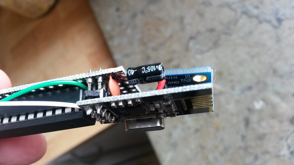
Here (and often in other projects as well) the GY-21 board is used to provide the Si7021 sensor . I'm not sure about the identity of components on it, but apart from the sensor the board also includes a small 3.3V-regulator (LDO), mosfets for logic level convertion, supporting capacitors and pull-up resistors.The voltage regulator is desoldered and bypassed in pictures above. This gained a node sleep current reduction from 10.7uA to ~6uA. This is the only modification necessary to do on the GY-21.
The GY-21 board is obviously designed for 5V-projects, but removing-/bypassing the v-reg is enough for using it in our low power 3.3-1.9V applications. @riataman was the first to show the mod of the GY-21 board in this post. There's also a link to a board without the v-reg and level converter. If you design you own pcb you'll probably use the Si7021 bare chip instead of the GY-21 board.
I had some thoughts about voltage dropout level and the level converter. In the end I still have thoughts, but my experiments show no issues. Here's a description of the level converter working principle. Remember that I don't know if these specs are equivalent, but looking at the mosfet datasheet, it says "Diode forward voltage drop 0.85-1.5V" and "Gate threshold voltage 1.0-2.5V". It's also an "Enhancment mode" FET, where the threshold voltage is important according to this. All together makes me worried about the High side capability to pull down Low side when High side volt is <2V instead of 5V. My tests show differently though. There are no real issues with this. The Si7021 worked down to ~1.7-1.8V with no significant difference whether the level converter was bypassed or not. Comparing one node with bypassed level converter to one without, showed ~1uA lower sleep mode current. But I assume it could just as well be a matter of the individual variations. If anyone like to bypass their level converter, here's a picture.
@m26872 There is another version of the SI7021 board without voltage regulator. This evening I will look up the link on Aliexpress. The boards are smaller then the GY-21 variant.
-
@m26872 My nodes are working correctly for the moment. Actually one is at 2.8v. Perhaps I will have problem when voltage will be lower !
David.
@carlierd Probably. That's why I ask what you use. DHT22 connected straight to 2AA will not utilize battery capacity. Higher battery voltage with step down regulator would be better - or maybe without, but with like 3AAs or so.
-
@m26872 : I don't use booster. You think it's necessary ? 90uA is really important for battery operation.
For the design off course I will make it open hardware :)
David.
-
@carlierd With Slim Node running at 1Mhz even with or without booster i am having hardtime making DHT22 work. I even tried different libraries but none of them works at 1Mhz. How did you get it work?
-
@carlierd Probably. That's why I ask what you use. DHT22 connected straight to 2AA will not utilize battery capacity. Higher battery voltage with step down regulator would be better - or maybe without, but with like 3AAs or so.
-
@carlierd With Slim Node running at 1Mhz even with or without booster i am having hardtime making DHT22 work. I even tried different libraries but none of them works at 1Mhz. How did you get it work?
-
-
@ar91 Please find the code I used in 3 different nodes. The good thing with the playground lib is that there is error message if dialog with DHT22 failed.
/**
 * The MySensors Arduino library handles the wireless radio link and protocol
 * between your home built sensors/actuators and HA controller of choice.
 * The sensors forms a self healing radio network with optional repeaters. Each
 * repeater and gateway builds a routing tables in EEPROM which keeps track of the
 * network topology allowing messages to be routed to nodes.
 *
 * Created by Henrik Ekblad <henrik.ekblad@mysensors.org>
 * Copyright (C) 2013-2015 Sensnology AB
 * Full contributor list: https://github.com/mysensors/Arduino/graphs/contributors
 *
 * Documentation: http://www.mysensors.org
 * Support Forum: http://forum.mysensors.org
 *
 * This program is free software; you can redistribute it and/or
 * modify it under the terms of the GNU General Public License
 * version 2 as published by the Free Software Foundation.
 *
 */

/**************************************************************************************/
/* Temperature, humidity and luminosity measurements.                                 */
/*                                                                                    */
/* Version     : 1.1.6                                                                */
/* Date        : 10/01/2016                                                           */
/* Modified by : David Carlier                                                        */
/**************************************************************************************/
/*                                ---------------                                     */
/*                            RST |             |  A5                                 */
/*                            RX  |             |  A4                                 */
/*                            TX  |   ARDUINO   |  A3                                 */
/*     RFM69 (DIO0) --------- D2  |     UNO     |  A2                                 */
/*            DHT22 --------- D3  |             |  A1                                 */
/*            Power --------- D4  | ATMEGA 328p |  A0 --------- Light dep. resistor   */
/*              +3v --------- VCC |             | GND --------- GND                   */
/*              GND --------- GND |  8MHz int.  | REF                                 */
/*                            OSC |             | VCC --------- +3v                   */
/*                            OSC |             | D13 --------- RFM69 (SCK)           */
/*                            D5  |             | D12 --------- RFM69 (MISO)          */
/*                            D6  |             | D11 --------- RFM69 (MOSI)          */
/*                            D7  |             | D10 --------- RFM69 (NSS)           */
/*                            D8  |             |  D9                                 */
/*                                ---------------                                     */
/*                                                                                    */
/* Power = Vcc for LDR.                                                               */
/* +3v = 2*AA                                                                         */
/*                                                                                    */
/**************************************************************************************/

#include <SPI.h>
#include <MySensor.h>
#include <dht.h>
#include <MyTransportRFM69.h>
#include <MySigningAtsha204Soft.h>

#define CHILD_ID_HUM 0
#define CHILD_ID_TEMP 1
#define CHILD_ID_LIGHT 2
#define CHILD_ID_VOLTAGE 3
#define LIGHT_SENSOR_ANALOG_PIN 0
#define HUMIDITY_SENSOR_DIGITAL_PIN 3
#define POWER_PIN 4
//unsigned long SLEEP_TIME = 850000; // Sleep time between reads (in milliseconds) (close to 15')
unsigned long SLEEP_TIME = 275000; // Sleep time between reads (in milliseconds) (close to 5')

//Construct MySensors library
MySigningAtsha204Soft signer;
MyHwATMega328 hw;
MyTransportRFM69 transport;
MySensor gw(transport, hw, signer);
dht DHT;
MyMessage msgHum(CHILD_ID_HUM, V_HUM);
MyMessage msgTemp(CHILD_ID_TEMP, V_TEMP);
MyMessage msgLum(CHILD_ID_LIGHT, V_LEVEL);
MyMessage msgVolt(CHILD_ID_VOLTAGE, V_VOLTAGE);

/**************************************************************************************/
/* Initialization                                                                     */
/**************************************************************************************/
void setup()
  {
  //Get time (for setup duration)
  #ifdef DEBUG
    unsigned long startTime = millis();
  #endif

  //Start MySensors
  gw.begin();

  //Send the Sketch Version Information to the Gateway
  gw.sendSketchInfo("GHAS sensor", "1.1.5");

  //Register all sensors to gw (they will be created as child devices)
  gw.present(CHILD_ID_HUM, S_HUM);
  gw.present(CHILD_ID_TEMP, S_TEMP);
  gw.present(CHILD_ID_LIGHT, S_LIGHT_LEVEL);
  gw.present(CHILD_ID_VOLTAGE, S_MULTIMETER);

  //Delay for DHT22
  delay(1500);

  //Print setup debug
  #ifdef DEBUG
    int duration = millis() - startTime;
    Serial.print("[Setup duration: "); Serial.print(duration, DEC); Serial.println(" ms]");
  #endif
  }

/**************************************************************************************/
/* Main loop                                                                          */
/**************************************************************************************/
void loop()
  {
  //Get time (for a complete loop)
  #ifdef DEBUG
    unsigned long startTime = millis();
  #endif

  //Power on
  powerOnPeripherals();

  //Get DHT22 data
  int dht22Result = DHT.read22(HUMIDITY_SENSOR_DIGITAL_PIN);
  switch (dht22Result)
    {
    case DHTLIB_OK:
                //Serial.println("OK,\t");
                break;
    case DHTLIB_ERROR_CHECKSUM:
                #ifdef DEBUG
                  Serial.println("Checksum error,\t");
                #endif
                break;
    case DHTLIB_ERROR_TIMEOUT:
                #ifdef DEBUG
                  Serial.println("Time out error,\t");
                #endif
                break;
    case DHTLIB_ERROR_CONNECT:
                #ifdef DEBUG
                  Serial.println("Connect error,\t");
                #endif
                break;
    case DHTLIB_ERROR_ACK_L:
                #ifdef DEBUG
                  Serial.println("Ack Low error,\t");
                #endif
                break;
    case DHTLIB_ERROR_ACK_H:
                #ifdef DEBUG
                  Serial.println("Ack High error,\t");
                #endif
                break;
    default:
                #ifdef DEBUG
                  Serial.println("Unknown error,\t");
                #endif
                break;
    }

  //Get temperature and humidity
  float temperature = 0;
  float humidity = 0;
  if (dht22Result == DHTLIB_OK)
    {
    temperature = DHT.temperature;
    humidity = DHT.humidity;
    }

  //Get power before luminosity to use real voltage
  float realVoltage = getVoltage() / 100.0;
  int batteryPcnt = realVoltage * 100 / 3.0;
  if (batteryPcnt > 100) {batteryPcnt = 100;}
  int lux = computeIlluminance(realVoltage);

  //Power off
  powerOffPeripherals();

  //Send data to gateway
  gw.send(msgHum.set(humidity, 1));
  gw.send(msgTemp.set(temperature, 1));
  gw.send(msgLum.set(lux));
  gw.send(msgVolt.set(realVoltage, 2));
  gw.sendBatteryLevel(batteryPcnt);

  //Print debug
  #ifdef DEBUG
    Serial.print(temperature, 1);
    Serial.print(" degC");
    Serial.print("   ");
    Serial.print(humidity, 1);
    Serial.print(" %");
    Serial.print("   ");
    Serial.print(lux);
    Serial.print(" lx");
    Serial.print("   ");
    Serial.print(realVoltage);
    Serial.print(" v");
    int duration = millis() - startTime;
    Serial.print("   ");
    Serial.print("["); Serial.print(duration, DEC); Serial.println(" ms]");
    Serial.flush();
  #endif

  //Sleep
  gw.sleep(SLEEP_TIME);
  }

/**************************************************************************************/
/* Allows to compute illuminance (in LUX) from LIGHT_SENSOR_ANALOG_PIN.               */
/**************************************************************************************/
int computeIlluminance(float realVoltage)
  {
  //Get luminosity
  int luminosity = analogRead(LIGHT_SENSOR_ANALOG_PIN);
  //Calculating the voltage in the input of the ADC
  double voltage = realVoltage * ((double)luminosity / 1024.0);
  //Calculating the resistance of the photoresistor in the voltage divider
  double resistance = (10.0 * realVoltage) / voltage - 10.0;
  //Calculating the intensity of light in lux and return it
  int illuminance = 255.84 * pow(resistance, -10/9);
  return illuminance;
  }

/**************************************************************************************/
/* Allows to get the real Vcc (return value * 100).                                   */
/**************************************************************************************/
int getVoltage()
  {
  const long InternalReferenceVoltage = 1056L;
  ADMUX = (0<<REFS1) | (1<<REFS0) | (0<<ADLAR) | (1<<MUX3) | (1<<MUX2) | (1<<MUX1) | (0<<MUX0);
  delay(50);  // Let mux settle a little to get a more stable A/D conversion
  //Start a conversion
  ADCSRA |= _BV( ADSC );
  //Wait for it to complete
  while (((ADCSRA & (1<<ADSC)) != 0));
  //Scale the value
  int result = (((InternalReferenceVoltage * 1023L) / ADC) + 5L) / 10L;
  return result;
  }

/**************************************************************************************/
/* Allows to power ON peripherals.                                                    */
/**************************************************************************************/
void powerOnPeripherals()
  {
  //Power-up
  pinMode (POWER_PIN, OUTPUT);
  digitalWrite (POWER_PIN, HIGH);
  delay(1);
  }

/**************************************************************************************/
/* Allows to power OFF peripherals.                                                   */
/**************************************************************************************/
void powerOffPeripherals()
  {
  //Power off
  digitalWrite (HUMIDITY_SENSOR_DIGITAL_PIN, LOW);
  digitalWrite (POWER_PIN, LOW);
  pinMode (HUMIDITY_SENSOR_DIGITAL_PIN, INPUT);
  pinMode (POWER_PIN, INPUT);
  }
Hope it helps !
David.
-
Progress!
http://imgur.com/zRvXvrN
http://imgur.com/KpB7dazA question though. To get to this point, I copied the pictures posted above, but where do I now add these resistors?
Also, if I want to add a 2AA battery cage, where do I connect the red and black wires to?
Thanks! And sorry for the newb questions!
-
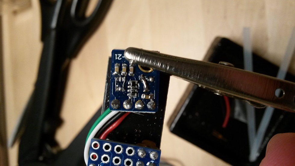
@rsachoc What you show are not resistors, they look like capacitors. 104 means 100nF (I think). Can you measure their value ?
-
@ar91 Please find the code I used in 3 different nodes. The good thing with the playground lib is that there is error message if dialog with DHT22 failed.
/**
 * The MySensors Arduino library handles the wireless radio link and protocol
 * between your home built sensors/actuators and HA controller of choice.
 * The sensors forms a self healing radio network with optional repeaters. Each
 * repeater and gateway builds a routing tables in EEPROM which keeps track of the
 * network topology allowing messages to be routed to nodes.
 *
 * Created by Henrik Ekblad <henrik.ekblad@mysensors.org>
 * Copyright (C) 2013-2015 Sensnology AB
 * Full contributor list: https://github.com/mysensors/Arduino/graphs/contributors
 *
 * Documentation: http://www.mysensors.org
 * Support Forum: http://forum.mysensors.org
 *
 * This program is free software; you can redistribute it and/or
 * modify it under the terms of the GNU General Public License
 * version 2 as published by the Free Software Foundation.
 *
 */

/**************************************************************************************/
/* Temperature, humidity and luminosity measurements.                                 */
/*                                                                                    */
/* Version     : 1.1.6                                                                */
/* Date        : 10/01/2016                                                           */
/* Modified by : David Carlier                                                        */
/**************************************************************************************/
/*                                ---------------                                     */
/*                            RST |             |  A5                                 */
/*                            RX  |             |  A4                                 */
/*                            TX  |   ARDUINO   |  A3                                 */
/*     RFM69 (DIO0) --------- D2  |     UNO     |  A2                                 */
/*            DHT22 --------- D3  |             |  A1                                 */
/*            Power --------- D4  | ATMEGA 328p |  A0 --------- Light dep. resistor   */
/*              +3v --------- VCC |             | GND --------- GND                   */
/*              GND --------- GND |  8MHz int.  | REF                                 */
/*                            OSC |             | VCC --------- +3v                   */
/*                            OSC |             | D13 --------- RFM69 (SCK)           */
/*                            D5  |             | D12 --------- RFM69 (MISO)          */
/*                            D6  |             | D11 --------- RFM69 (MOSI)          */
/*                            D7  |             | D10 --------- RFM69 (NSS)           */
/*                            D8  |             |  D9                                 */
/*                                ---------------                                     */
/*                                                                                    */
/* Power = Vcc for LDR.                                                               */
/* +3v = 2*AA                                                                         */
/*                                                                                    */
/**************************************************************************************/

#include <SPI.h>
#include <MySensor.h>
#include <dht.h>
#include <MyTransportRFM69.h>
#include <MySigningAtsha204Soft.h>

#define CHILD_ID_HUM 0
#define CHILD_ID_TEMP 1
#define CHILD_ID_LIGHT 2
#define CHILD_ID_VOLTAGE 3
#define LIGHT_SENSOR_ANALOG_PIN 0
#define HUMIDITY_SENSOR_DIGITAL_PIN 3
#define POWER_PIN 4
//unsigned long SLEEP_TIME = 850000; // Sleep time between reads (in milliseconds) (close to 15')
unsigned long SLEEP_TIME = 275000; // Sleep time between reads (in milliseconds) (close to 5')

//Construct MySensors library
MySigningAtsha204Soft signer;
MyHwATMega328 hw;
MyTransportRFM69 transport;
MySensor gw(transport, hw, signer);
dht DHT;
MyMessage msgHum(CHILD_ID_HUM, V_HUM);
MyMessage msgTemp(CHILD_ID_TEMP, V_TEMP);
MyMessage msgLum(CHILD_ID_LIGHT, V_LEVEL);
MyMessage msgVolt(CHILD_ID_VOLTAGE, V_VOLTAGE);

/**************************************************************************************/
/* Initialization                                                                     */
/**************************************************************************************/
void setup()
  {
  //Get time (for setup duration)
  #ifdef DEBUG
    unsigned long startTime = millis();
  #endif

  //Start MySensors
  gw.begin();

  //Send the Sketch Version Information to the Gateway
  gw.sendSketchInfo("GHAS sensor", "1.1.5");

  //Register all sensors to gw (they will be created as child devices)
  gw.present(CHILD_ID_HUM, S_HUM);
  gw.present(CHILD_ID_TEMP, S_TEMP);
  gw.present(CHILD_ID_LIGHT, S_LIGHT_LEVEL);
  gw.present(CHILD_ID_VOLTAGE, S_MULTIMETER);

  //Delay for DHT22
  delay(1500);

  //Print setup debug
  #ifdef DEBUG
    int duration = millis() - startTime;
    Serial.print("[Setup duration: "); Serial.print(duration, DEC); Serial.println(" ms]");
  #endif
  }

/**************************************************************************************/
/* Main loop                                                                          */
/**************************************************************************************/
void loop()
  {
  //Get time (for a complete loop)
  #ifdef DEBUG
    unsigned long startTime = millis();
  #endif

  //Power on
  powerOnPeripherals();

  //Get DHT22 data
  int dht22Result = DHT.read22(HUMIDITY_SENSOR_DIGITAL_PIN);
  switch (dht22Result)
    {
    case DHTLIB_OK:
                //Serial.println("OK,\t");
                break;
    case DHTLIB_ERROR_CHECKSUM:
                #ifdef DEBUG
                  Serial.println("Checksum error,\t");
                #endif
                break;
    case DHTLIB_ERROR_TIMEOUT:
                #ifdef DEBUG
                  Serial.println("Time out error,\t");
                #endif
                break;
    case DHTLIB_ERROR_CONNECT:
                #ifdef DEBUG
                  Serial.println("Connect error,\t");
                #endif
                break;
    case DHTLIB_ERROR_ACK_L:
                #ifdef DEBUG
                  Serial.println("Ack Low error,\t");
                #endif
                break;
    case DHTLIB_ERROR_ACK_H:
                #ifdef DEBUG
                  Serial.println("Ack High error,\t");
                #endif
                break;
    default:
                #ifdef DEBUG
                  Serial.println("Unknown error,\t");
                #endif
                break;
    }

  //Get temperature and humidity
  float temperature = 0;
  float humidity = 0;
  if (dht22Result == DHTLIB_OK)
    {
    temperature = DHT.temperature;
    humidity = DHT.humidity;
    }

  //Get power before luminosity to use real voltage
  float realVoltage = getVoltage() / 100.0;
  int batteryPcnt = realVoltage * 100 / 3.0;
  if (batteryPcnt > 100) {batteryPcnt = 100;}
  int lux = computeIlluminance(realVoltage);

  //Power off
  powerOffPeripherals();

  //Send data to gateway
  gw.send(msgHum.set(humidity, 1));
  gw.send(msgTemp.set(temperature, 1));
  gw.send(msgLum.set(lux));
  gw.send(msgVolt.set(realVoltage, 2));
  gw.sendBatteryLevel(batteryPcnt);

  //Print debug
  #ifdef DEBUG
    Serial.print(temperature, 1);
    Serial.print(" degC");
    Serial.print("   ");
    Serial.print(humidity, 1);
    Serial.print(" %");
    Serial.print("   ");
    Serial.print(lux);
    Serial.print(" lx");
    Serial.print("   ");
    Serial.print(realVoltage);
    Serial.print(" v");
    int duration = millis() - startTime;
    Serial.print("   ");
    Serial.print("["); Serial.print(duration, DEC); Serial.println(" ms]");
    Serial.flush();
  #endif

  //Sleep
  gw.sleep(SLEEP_TIME);
  }

/**************************************************************************************/
/* Allows to compute illuminance (in LUX) from LIGHT_SENSOR_ANALOG_PIN.               */
/**************************************************************************************/
int computeIlluminance(float realVoltage)
  {
  //Get luminosity
  int luminosity = analogRead(LIGHT_SENSOR_ANALOG_PIN);
  //Calculating the voltage in the input of the ADC
  double voltage = realVoltage * ((double)luminosity / 1024.0);
  //Calculating the resistance of the photoresistor in the voltage divider
  double resistance = (10.0 * realVoltage) / voltage - 10.0;
  //Calculating the intensity of light in lux and return it
  int illuminance = 255.84 * pow(resistance, -10/9);
  return illuminance;
  }

/**************************************************************************************/
/* Allows to get the real Vcc (return value * 100).                                   */
/**************************************************************************************/
int getVoltage()
  {
  const long InternalReferenceVoltage = 1056L;
  ADMUX = (0<<REFS1) | (1<<REFS0) | (0<<ADLAR) | (1<<MUX3) | (1<<MUX2) | (1<<MUX1) | (0<<MUX0);
  delay(50);  // Let mux settle a little to get a more stable A/D conversion
  //Start a conversion
  ADCSRA |= _BV( ADSC );
  //Wait for it to complete
  while (((ADCSRA & (1<<ADSC)) != 0));
  //Scale the value
  int result = (((InternalReferenceVoltage * 1023L) / ADC) + 5L) / 10L;
  return result;
  }

/**************************************************************************************/
/* Allows to power ON peripherals.                                                    */
/**************************************************************************************/
void powerOnPeripherals()
  {
  //Power-up
  pinMode (POWER_PIN, OUTPUT);
  digitalWrite (POWER_PIN, HIGH);
  delay(1);
  }

/**************************************************************************************/
/* Allows to power OFF peripherals.                                                   */
/**************************************************************************************/
void powerOffPeripherals()
  {
  //Power off
  digitalWrite (HUMIDITY_SENSOR_DIGITAL_PIN, LOW);
  digitalWrite (POWER_PIN, LOW);
  pinMode (HUMIDITY_SENSOR_DIGITAL_PIN, INPUT);
  pinMode (POWER_PIN, INPUT);
  }
Hope it helps !
David.
-
@GertSanders indeed they are capacitors (silly me) - apparently they are 0.1uf - the black one I have already soldered is 4.7uf
-
@carlierd Are you running your Atmega at 1Mhz, Because I tried to use your sketch and i am getting "Checksum Error".
-
Bump, can anyone advise on how I got about finding out where I need to solder the resistors on? So far I've just soldered the 4.7uf capacitor, as can be seen from the pics. But I'm struggling to find out where I need to solder the other capacitor's I have (from the BOM).
-
Bump, can anyone advise on how I got about finding out where I need to solder the resistors on? So far I've just soldered the 4.7uf capacitor, as can be seen from the pics. But I'm struggling to find out where I need to solder the other capacitor's I have (from the BOM).
@rsachoc C1,C2,C3 are clearly marked at top layer silkscreen. You'll see them in the middle of the uC socket if you look at your 2nd picture in you last post above. C5 is visible next to the 4.7u cap, in the 3rd picture of my first post in this thread.
Hello! It looks like you're interested in this conversation, but you don't have an account yet.
Getting fed up of having to scroll through the same posts each visit? When you register for an account, you'll always come back to exactly where you were before, and choose to be notified of new replies (either via email, or push notification). You'll also be able to save bookmarks and upvote posts to show your appreciation to other community members.
With your input, this post could be even better 💗
Register Login