Universal wireless sensor board w/NRF24l01+ and ESP8266 socket - ceech board
-
They are extra. Enjoy.
-
EDITED
Nevermind!!
"- with CE and CSN pins connected to digital pins 7 and 8 (you must update MyConfig.h with these values). There is a 4.7uF capacitor connected across Vin and GND of the port"
@shabba You do not need to update MyConfig.h. Just instantiate MySensor with the right parameters (default is 9, 10).
// PIN Radio #define RADIO_CE_PIN 7 // radio chip enable #define RADIO_SS_PIN 8 // CS SS serial select ... MySensor gw(RADIO_CE_PIN, RADIO_SS_PIN); -
Hello,
I'm trying mine... any idea why the gateway doesn't receive it at 20cm distance ?
req node id send: 255-255-255-0 s=255,c=3,t=3,pt=0,l=0,st=fail: sensor started, id 255 req node id send: 255-255-255-0 s=255,c=3,t=3,pt=0,l=0,st=fail: req node id send: 255-255-255-0 s=255,c=3,t=3,pt=0,l=0,st=fail: req node id send: 255-255-255-0 s=255,c=3,t=3,pt=0,l=0,st=fail: req node id send: 255-255-255-0 s=255,c=3,t=3,pt=0,l=0,st=fail: -
@ceech I have an issue on a board (lipo+solar) where when I put the programmer it works, when I remove it and leave it on battery it doesn't... battery is 94%, I checked sensors get the energy.. but no more radio it seems, an idea ?
-
@ceech I have an issue on a board (lipo+solar) where when I put the programmer it works, when I remove it and leave it on battery it doesn't... battery is 94%, I checked sensors get the energy.. but no more radio it seems, an idea ?
-
on this one this is the lipo+solar.
On the other thread, I mistakenly ordered the "standard" version through mysensor website, and had no time till now to test this out... so bard both weren't proposed...
-
on this one this is the lipo+solar.
On the other thread, I mistakenly ordered the "standard" version through mysensor website, and had no time till now to test this out... so bard both weren't proposed...
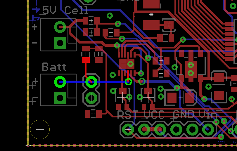
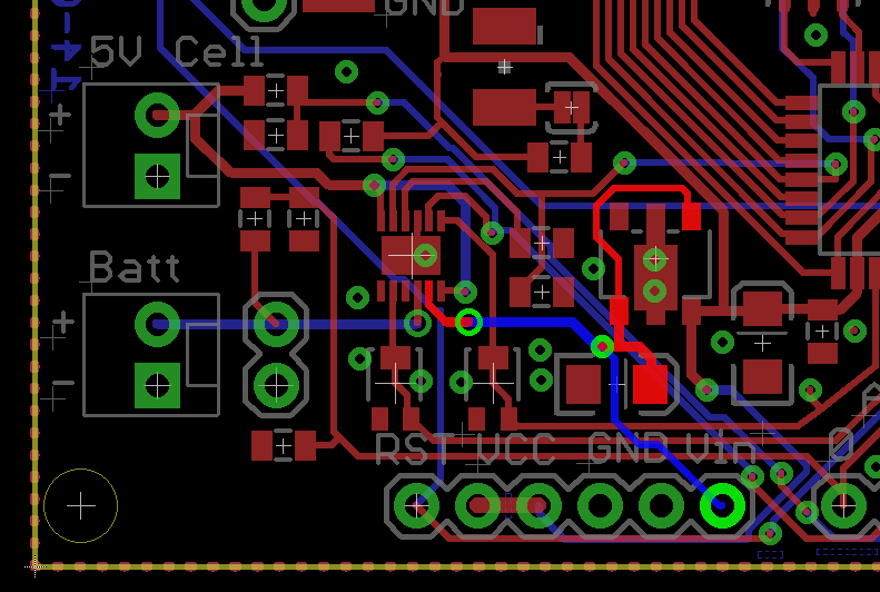
@epierre The battery is connected with the marked trace:
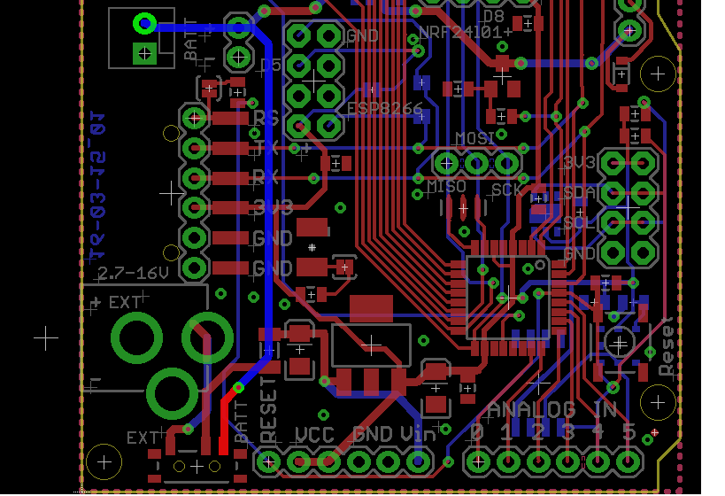
It goes to the switch an over to the voltage regulator:
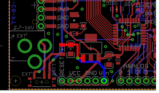
You should measure battery voltage along those lines with respect to the GND. On the other side of the voltage regulator there should be 3V3.
On the side note -- you can use those boards that you've mentioned on the other thread to charge the battery. No problem.
-
@epierre The battery is connected with the marked trace:
It goes to the switch an over to the voltage regulator:
You should measure battery voltage along those lines with respect to the GND. On the other side of the voltage regulator there should be 3V3.
On the side note -- you can use those boards that you've mentioned on the other thread to charge the battery. No problem.
-
@ceech said:
along those lines with respect to the GND. On the other side of the voltage regulator there should be 3V3.
thanks, but I should not have mixed both, my issue is with the other one.
-
on the LCT4067, I have 4.17 , on the battery, VCC/GND gives 1.608, same on programmer pin. But this is correct with the programmer, so I get I have an issue from the battery circuit voltage transformation.
on the standard one LTC4079, voltages are correct, 4.17 on Vin/GND, 3.3 on VCC/GND
-
on the LCT4067, I have 4.17 , on the battery, VCC/GND gives 1.608, same on programmer pin. But this is correct with the programmer, so I get I have an issue from the battery circuit voltage transformation.
on the standard one LTC4079, voltages are correct, 4.17 on Vin/GND, 3.3 on VCC/GND
-
@ceech said:
. Can you send me the board back?
I'll repair it and send you back.hello fine, also I wanted to try the thermopile so there will be more on return ;-)
In the meanwhile, how can I have my solar panel on the LTC4079 ? can the lithium charger do the trick ?
Thanks,
-
@ceech said:
. Can you send me the board back?
I'll repair it and send you back.hello fine, also I wanted to try the thermopile so there will be more on return ;-)
In the meanwhile, how can I have my solar panel on the LTC4079 ? can the lithium charger do the trick ?
Thanks,
-
@ceech said:
had to replace the battery management IC. The LTC4067. The output was fried. I also replaced the voltage regulator while I was at it.
@ceech thanks a lot, any idea why this would happen ?
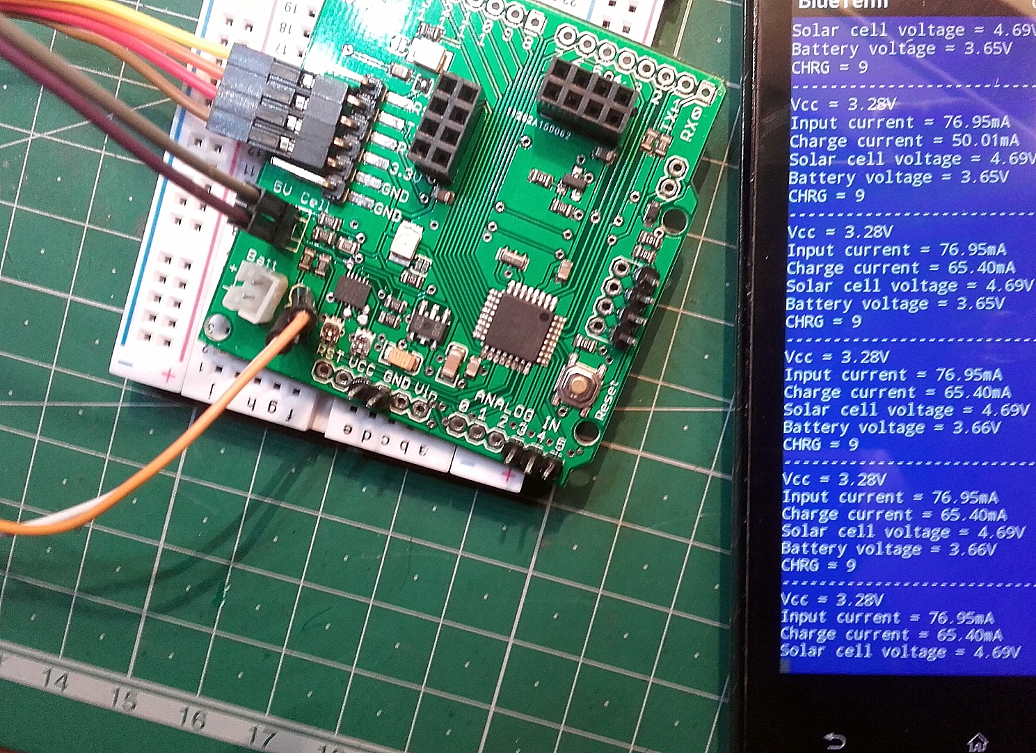
what kind of bluetooth module are you using ? I've managed nothing good with the HC-05, maybe faulty hard to know.
-
There are current limiters on input and output side. So short circuit is out of the question. Maybe overvoltage on the input side.
Yes, that's HC-05. Just use it as a serial monitor. It's the same.
Hello! It looks like you're interested in this conversation, but you don't have an account yet.
Getting fed up of having to scroll through the same posts each visit? When you register for an account, you'll always come back to exactly where you were before, and choose to be notified of new replies (either via email, or push notification). You'll also be able to save bookmarks and upvote posts to show your appreciation to other community members.
With your input, this post could be even better 💗
Register Login