Universal wireless sensor board w/NRF24l01+ and ESP8266 socket - ceech board
-
This board is made for low-power applications and can be used as an universal board for wireless sensor node networks. It can be powered from battery or external source. Dimensions are 2 inch x 2.1 inch.
There are three sockets:- for NRF24l01+ module
- for ESP8266 ESP-01
- and an I2C socket
The board is powered with a Microchip MCP1703 3.3V voltage regulator.
On the back, there is place for BMP180, HTU21, additional EEPROM and for TC series Mosfet driver.
Here is a link to the schematic: http://i.imgur.com/DbALMmf.pngThe board is available here, on http://www.mysensors.org/hardware/ceech
-
This is without solar cell input, right?
What are the main advantage to this over your board on ebay in terms of battery life?
( I want a long battery life for a ultrasonic snow depth sensor, a DS18B20 and maybe a BMP180 located outside)
-
@larky Yes, that's right.
It depends. The voltage regulator on this board has lower consumption than the voltage regulator on the one with the solar charger. So this board is more efficient.
However, there is a battery charger on the other board, which charges the battery.
It is a matter of choice, really.
I would say - use this board if you like to keep things simple and do not need high current sensors. Use the board with solar battery charger for sensors that require more power. For example MQ-series air quality sensors tend to use a lot of current.
-
So what is needed with this board? The radio and whatever sensor someone wants?
-
@shabba Yes, a radio module and a sensor(sensors). There is place on the back for two of them.
-
Hi @ceech, the link to the board info (above) on the MySensors website still talks about the old board. I assume if we purchase through MySensors we will indeed be getting this updated board? Looks really nice by the way. Thanks very much.
Cheers
Richard
-
@hawk_2050 Thank you. Yes, all orders are linked to this, new board. I'll ask @hek to change the description at the next page update.
-
Just received 2 pcs of the board, thanks for quick delivery.
Concerned how to supply them, I don't want to damage them.
What is the voltage range for "BATT" ?
Will power connected to BATT go through the MVP1703 regulator?
I plan to connect BATT to 2 AA batteries (3V) or an separate 3.3 v source on my breadbord.Thanks,
Pär
-
The power from either BATT or EXT goes through the voltage regulator. It only consumes 2uA, so it is fairly efficient and its maximum input voltage is 16V. So that is max for BATT as well as EXT. If you would like to power the board directly, then I would suggest connecting the power source via VCC pins on the lower left connector. There are two of them, the second and third from the left. The maximum input voltage for those pins is 5V, or 3V3, if you are going to use radio module.
-
Since this board can take both a NRF24l01+ module and ESP8266 ESP-01 it could be an ethernet gateway?
-
Yes, it can. If you are willing to try, I can send you one board and you can test that if you are up for it. Just post the code here, when you make it work. Send me a message and we can discuss it further if you like.
-
I just want to confirm a few things before I buy :
- What is needed to programme this? Can it be done via an FTDI board?
- What bootloader is on it?
- Besides a sensor and radio (and power) nothing else needs to be added/soldered right?
Thanks!
-
- Yes, it can. With FTDI or similar board. It is the same process as with Arduino Pro mini.
- Which is also the bootloader - Arduino Pro or Pro Mini (ATmega328, 8MHz, 3.3V)
- Nothing else is needed.
-
Thanks. Ordered a couple.
-
I'm having a slow day so bear with me
Where do I connect the LEDs? Also what is the name of the white sockets? I want to google procedure for adding wire to the plug part.
Many thanks
-
Warning to others : I blew a radio by connecting a 5V programmer. There seems to be no protection from USB power to the radio.
-
I'm sorry to hear that. Is there something I can do?
The LEDs have solder jumpers next to them. The top one has one to the left, and the bottom one has one to the right. Just pour solder so that both parts of the jumper get connected.
The white connector is Japan Solderless Terminal or JST. I believe it is a XH series with 0.1 inch spacing. The way I connect the wire is I bend the longer ears with pliers over the isolated wire and use solder iron to solder the shorter ears to the stripped wire.
-
I see the LEDs and understand now. I had got some loose in the shipping packet and thought I had to solder them onto the board.
-
They are extra. Enjoy.
-
EDITED
Nevermind!!
"- with CE and CSN pins connected to digital pins 7 and 8 (you must update MyConfig.h with these values). There is a 4.7uF capacitor connected across Vin and GND of the port"
-
@shabba You do not need to update MyConfig.h. Just instantiate MySensor with the right parameters (default is 9, 10).
// PIN Radio #define RADIO_CE_PIN 7 // radio chip enable #define RADIO_SS_PIN 8 // CS SS serial select ... MySensor gw(RADIO_CE_PIN, RADIO_SS_PIN);
-
Hello,
I'm trying mine... any idea why the gateway doesn't receive it at 20cm distance ?
req node id send: 255-255-255-0 s=255,c=3,t=3,pt=0,l=0,st=fail: sensor started, id 255 req node id send: 255-255-255-0 s=255,c=3,t=3,pt=0,l=0,st=fail: req node id send: 255-255-255-0 s=255,c=3,t=3,pt=0,l=0,st=fail: req node id send: 255-255-255-0 s=255,c=3,t=3,pt=0,l=0,st=fail: req node id send: 255-255-255-0 s=255,c=3,t=3,pt=0,l=0,st=fail:
-
@ceech sorry seems the radio was dead ...
-
@ceech I have an issue on a board (lipo+solar) where when I put the programmer it works, when I remove it and leave it on battery it doesn't... battery is 94%, I checked sensors get the energy.. but no more radio it seems, an idea ?
-
@epierre It is probably a loose contact on the battery connector. Try using a multimeter and check the important connections.
-
@ceech can you point me to the wirings ? thanks,
-
@epierre Which board are you using?
-
on this one this is the lipo+solar.
On the other thread, I mistakenly ordered the "standard" version through mysensor website, and had no time till now to test this out... so bard both weren't proposed...
-
@epierre The battery is connected with the marked trace:
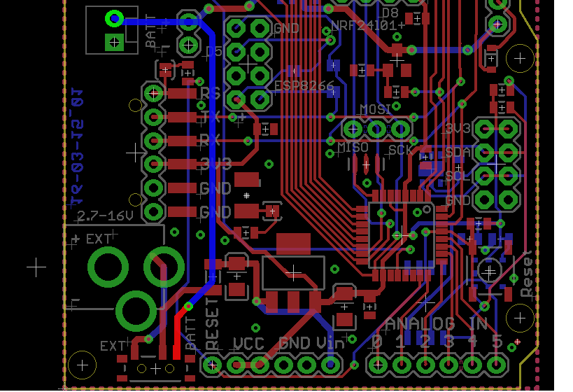
It goes to the switch an over to the voltage regulator:
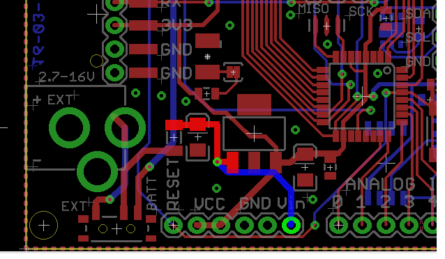
You should measure battery voltage along those lines with respect to the GND. On the other side of the voltage regulator there should be 3V3.
On the side note -- you can use those boards that you've mentioned on the other thread to charge the battery. No problem.
-
@ceech said:
along those lines with respect to the GND. On the other side of the voltage regulator there should be 3V3.
thanks, but I should not have mixed both, my issue is with the other one.
-
@epierre The one with LTC4067 or the one with LTC4079? It's probably the one with LTC4067.
Here, this is the battery path to the charger:
and then to the voltage regulator:
-
on the LCT4067, I have 4.17 , on the battery, VCC/GND gives 1.608, same on programmer pin. But this is correct with the programmer, so I get I have an issue from the battery circuit voltage transformation.
on the standard one LTC4079, voltages are correct, 4.17 on Vin/GND, 3.3 on VCC/GND
-
@epierre It's either the LTC4067, or the voltage regulator. Can you send me the board back?
I'll repair it and send you back.
-
@ceech said:
. Can you send me the board back?
I'll repair it and send you back.hello fine, also I wanted to try the thermopile so there will be more on return
In the meanwhile, how can I have my solar panel on the LTC4079 ? can the lithium charger do the trick ?
Thanks,
-
@epierre I've received the board and repaired it. I had to replace the battery management IC. The LTC4067. The output was fried. I also replaced the voltage regulator while I was at it.
-
@ceech said:
had to replace the battery management IC. The LTC4067. The output was fried. I also replaced the voltage regulator while I was at it.
@ceech thanks a lot, any idea why this would happen ?
what kind of bluetooth module are you using ? I've managed nothing good with the HC-05, maybe faulty hard to know.
-
There are current limiters on input and output side. So short circuit is out of the question. Maybe overvoltage on the input side.
Yes, that's HC-05. Just use it as a serial monitor. It's the same.
-
@ceech for the solar panel and lipo version, could you let me know what type of battery and panel I shoulld buy? Also, is there a tutorial for usage of that version? I am new in solar panel and cahrging batteries. Thanks
-
@nunver The best solar panel is the one with voltages between 5 and 12 volts. And the board is set for a standard 3.7V Li-ion single cell battery. I've just updated the board with a DC-DC buck-boost converter which works below and above battery voltage. There is also plenty of other information on the following page:
http://www.ebay.com/itm/331800929918?ssPageName=STRK:MESELX:IT&_trksid=p3984.m1586.l2649
-
@ceech what did you use for soldering, I cannot see it myself (sure I have a lot to learn for SMD soldering...
-
@epierre I normally use a reflow oven and in your case I had to use a heat gun.