💬 MySensors Stable Node
-
Let's hope the change it :-)
Would it be possible to mount something like this on the pcb ?
-
Couple of questions :-)
How to mount the second Quartz crystal ?, there are no holes in the pcb
The LDO regulators are mounted next to 4.7uf capacitors, is it correct that the regulators and capacitors are connected to eachother on both sides ?
On the photo of the assembled pcb it looks like this, but on the photo of the plain pcb and the schematic it look different.
                                           | Pin 1
                                          IC3
                             Pin2    |          | Pin 3
        Are pin 2 and 3 also connected to the capacitor left and right pin ?
                          Left pin   |    C14   | Right pin
Thanks !!
Alex
@Slorf
Q1? Q1 is smd quartz. Q2 can be smd too but it can be difficult to mount it (so I've placed holes).I do not understand about LDO. You can check pinout in datasheet http://www.torexsemi.com/products/voltage_regulators/data/XC6206.pdf . May be datasheet schematic model (picture) is different from my library schematic model. But schematic and layout are correct.
-
Hi, the bom says 2 x quartz crystal
I did not know they where different and one should be smd.
Could you tell me which quartz crystals I should get ?
Will check out the datasheet for the LDO :-)
Thanks
Alex
@Slorf I've left the package field in bom blank, so you can use any crystal you have. All components on the board are smd, so crystal should be smd too if you have it. But it may be difficult to place smd crystal as Q2 (too small area) and I've placed holes. I have both SMD and THD crystals but I will put holes in Q1 crystal pads in the next version too. Now you can simply mount THD crystal on the pads, it's not difficult.
@Slorf said:
Would it be possible to mount something like this on the pcb?
It's possible. But I want this board to be as compact as possible.
@ahmedadelhosni said:
Great board.
Did you test the performance ? Like number of recieved packets per second ?Thanks. I've tested stability (for some months without troubles in typical applications) and RF range. I think it doesn't make sense to test performance with low performance mcu, but you can propose the sketch and I test with it.
-
I have both versions ( SMD and THD ) crystals on order with aliexpress now :-)
As for the LDO regulators, I will wait for the PCB's to arrive before making assumptions ;-)
Now I have to wait some weeks before everything arrives ........and then my first smd soldering experience !
Alex
-
Hi,
Very nice project. Do you have a plan to sell assembled piece of the boards?
Soldering such small SMD is out of my skills -
@Koresh I'm looking forward. What do you think, what will be the price of a assembled piece?
-
@fisher The production of the first small batch is underway (manual mounting). So I wil have 20 boards for test next week. I will provide price estimate in a week.
@Koresh post pictures please :-)
-
Hi @Koresh,
Sorry if this is a dumb question but I'm new to this. What's the minimum voltage to power this board? Is it the 1.9V from the NRF?
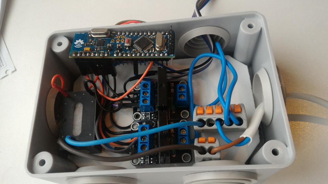
I'm thinking of building a node with this using a LiPo battery with a protected TP4056 charging module.
If me idea isn't impossible I'd be highly interested to buy some assembled units of this PCB. :)
Thanks! -
Hi @Koresh,
Sorry if this is a dumb question but I'm new to this. What's the minimum voltage to power this board? Is it the 1.9V from the NRF?
I'm thinking of building a node with this using a LiPo battery with a protected TP4056 charging module.
If me idea isn't impossible I'd be highly interested to buy some assembled units of this PCB. :)
Thanks!@flozsc
Hi. Minimum operating voltage depends on clock frequency. Boards contain standard 16MHz crystal oscillator to full pro mini compatibility. If you use default bootloader and 16Mhz clock frequency, the board will work with a voltage above 2.7v (on the verge of stability). But you can use internal oscillator (custom arduino boards settings, for example 8MHz or 1MHz for lowerst operating voltage) with some limitations (like slower serial). In this case operating voltage should be above 2--2.1v (do not forget a little dropout of LDO regulator). -
@Koresh Thanks for your quick reply.
Sleeping sometimes helps. ;-) After thinking over it again, I think I'll prepend a step-up converter to 5V behind the battery as most sensors at least require 3.3V or even 5V... :)
Looking forward to your update on the 20 test boards! -
Impressive !!
did you reflow the board, or did you REALLY manually solder the nrf24l chip with an iron ??? -
Impressive !!
did you reflow the board, or did you REALLY manually solder the nrf24l chip with an iron ???@fifipil909 Thanks.
I've soldered these boards using simple soldering iron and hot air fan (lukey 702). -
First small batch is completed :)
Hello! It looks like you're interested in this conversation, but you don't have an account yet.
Getting fed up of having to scroll through the same posts each visit? When you register for an account, you'll always come back to exactly where you were before, and choose to be notified of new replies (either via email, or push notification). You'll also be able to save bookmarks and upvote posts to show your appreciation to other community members.
With your input, this post could be even better 💗
Register Login