NRF24L01+ range of only few meters
-
@LastSamurai can't really say for this modules.
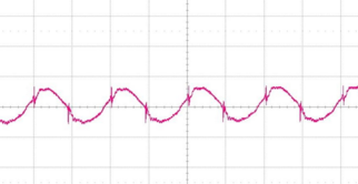
The datasheet for the LM2596 says you should use a post ripple filter for low noise, because it generates sawtooth ripple at its switching frequency (150khz). The china-clones of the lm2596 seem to be even worse generating even greater ripple with 50khz.Whats the ic on the mini dc-dc converter called? The ebay offer says it has a output ripple of 30mV bute more then often these values are the best case. Maybe a datasheets is available.
-
It would be so useful to be able to measure the supply voltages with an oscilloscope. So far all my transmission problems have been related to the power supplies. Only after using a scope I fully realized that. No more freezing or poor function of the nodes.
Also, using a brand supply doesn't necessarily mean a clean signal. This (again) is an illustrative post about USB supplies, worth to take a look at:
http://www.righto.com/2012/10/a-dozen-usb-chargers-in-lab-apple-is.html -
It would be so useful to be able to measure the supply voltages with an oscilloscope. So far all my transmission problems have been related to the power supplies. Only after using a scope I fully realized that. No more freezing or poor function of the nodes.
You are totally right! Unfortunately i also don't own a oscilloscope. But a cheaper usb oscilloscope is on my need to have list because of a all the trouble and testing i had with this...
-
It would be so useful to be able to measure the supply voltages with an oscilloscope. So far all my transmission problems have been related to the power supplies. Only after using a scope I fully realized that. No more freezing or poor function of the nodes.
You are totally right! Unfortunately i also don't own a oscilloscope. But a cheaper usb oscilloscope is on my need to have list because of a all the trouble and testing i had with this...
@Oitzu DSO138 scope is like $25 from aliexpress
-
@Igor-Katkov said:
DSO138
Was thinking of something like the Hantek 6022BE. Most EE guys would say "eh... crap", but oh well.. it's just a hobby and i'm not willing to pay hundreds of dollars for it. :D
-
One might think that to measure ripple noise of $2 Chinese power supply ~$70 unit is an overkill :-)
-
@Igor-Katkov eh... now you just sound like my gf. :P
No, you're right. But it may come handy in some other situations. :) -
It would be so useful to be able to measure the supply voltages with an oscilloscope. So far all my transmission problems have been related to the power supplies. Only after using a scope I fully realized that. No more freezing or poor function of the nodes.
Also, using a brand supply doesn't necessarily mean a clean signal. This (again) is an illustrative post about USB supplies, worth to take a look at:
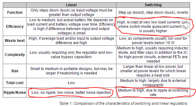
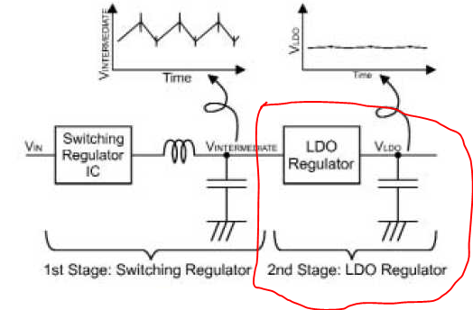
http://www.righto.com/2012/10/a-dozen-usb-chargers-in-lab-apple-is.html@Nuubi My two cents.. I have been measuring (with a scope ;)) quite a lot of power supplies and have come to the conclusion that most (inexpensive) switching power regulators (buck & boost) should be avoided when a clean supply is needed. All (or most) of these just not have enough filtering (LC) for the switching frequency. So go for a 'linear' version (for buck/ step-down), especially for the radio. Also PIR sensors are very sensitive.
Lucky for us most MySensors circuits need very little power, so the efficiency of a linear converter (for buck) is sufficient in most cases.
from digikey
or use a linear converter as "second stage"
-
@Oitzu Looks like the chips are these.
Btw I am using a cheap DS201 and I am happy with it for most cases. Sometimes I wish for a second channel but you can carry it around which is a big plus :)
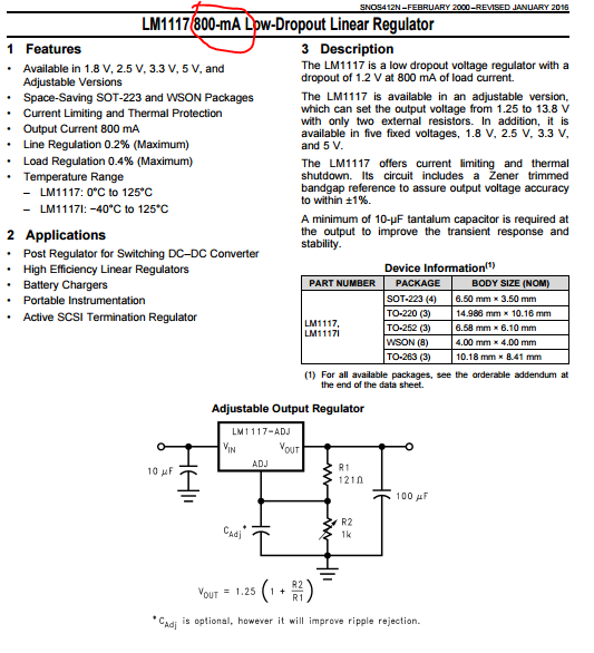
@AWI I have to convert 12V to 3.3V which is a big jump. So you think a linear regulator would work here? Something like a LM 1117 T3,3? Doesn't that get too hot if I constantly power the arduino, the radio and potentially a sensor?
PS has someone tried this? Otherwise the second stage LDO (something small, smd) would be an idea too. -
@Oitzu Looks like the chips are these.
Btw I am using a cheap DS201 and I am happy with it for most cases. Sometimes I wish for a second channel but you can carry it around which is a big plus :)
@AWI I have to convert 12V to 3.3V which is a big jump. So you think a linear regulator would work here? Something like a LM 1117 T3,3? Doesn't that get too hot if I constantly power the arduino, the radio and potentially a sensor?
PS has someone tried this? Otherwise the second stage LDO (something small, smd) would be an idea too.@LastSamurai No problem at all if you solder it on a copper plane. Most sensor circuits take less than 20mA.
I actually use the 662K LDO as a second stage with a step-up converter, works like a charm.
For the LM1117 (=not a real Low Dropout) the input voltage can be up to 20V.
-
@LastSamurai https://www.adafruit.com/datasheets/MP2307_r1.9.pdf
seems to be more complete and well.. a filter or a second stage would be recommend.@AWI i'm actually have a project running from 12v lead batteries, best way would be to use 2 stages?
ATM i'm using an additional lc-filter to get the ripple out. -
Could you perhaps actually use the onboard voltage regulator of the pro mini for powering the mini + nrf + random sensor? That would be the easiest + cheapest methode. Perhaps add one cap.
-
@LastSamurai depends on the used onboard regulator and the used nrf + random sensor.
But yes, this works also, most of the time on non pa/lna modules. -
@Oitzu in case you are looking for a cheap DIY osci, I'm going to build a Girino (http://www.instructables.com/id/Girino-Fast-Arduino-Oscilloscope/?ALLSTEPS) when I find the time. There is also an frontent on github (https://github.com/Chatanga/Girinoscope/tree/v1.0.1-beta). Seems to be quite simple and with very cheap hardware, so don't expect too much. But to have a look at some voltage levels and ripple it might be ok.
And when using it with a battery powered laptop you should be even ok with potential-free measurements. -
@mfalkvidd Yes, a few more meters with PA_MAX.
Here is my best performing coderadio.setPALevel(RF24_PA_MAX); radio.setDataRate(RF24_250KBPS); radio.setPayloadSize(4); radio.setChannel(2); radio.setRetries(15, 15);Full code https://gist.github.com/ikatkov/6df540838bd4d3ea8b57
-
@sven on the video he shows 83.38 ?? you are right, it is 2.4GHz
1/4 wave antenna is 31.25 mm long
1/2 wavelength is 62.5mm.so why did he mesured 83.38 ? was it inches ? (imperial non universal?)
I'd be surprised if the existing on board antenna is anything else than a 1/4 wave length of the center frequency for the NRF24L01 module. Therefore I BELIEVE that the right thing would be to extend it with antother 3/4 to make it a full wave length.
If you run it at the default MySensors frequency which is 2476 MHz, a full wave length is 121 mm. Therefore I'd assume that adding another 91 mm to the existing antenna would be the correct length. I haven't tried it yet though but I will.
Cheers!
-
I'm currently in the process of trying to figure out why one of my battery powered nodes isn't working very well with a newly purchased NRF24L01+PA+LNA module. I've shielded it as described in earlier posts. There is plenty of pure power in the batteries.
Just as in the case for @pkjjneal it works well only if I'm touching the antenna with a finger.
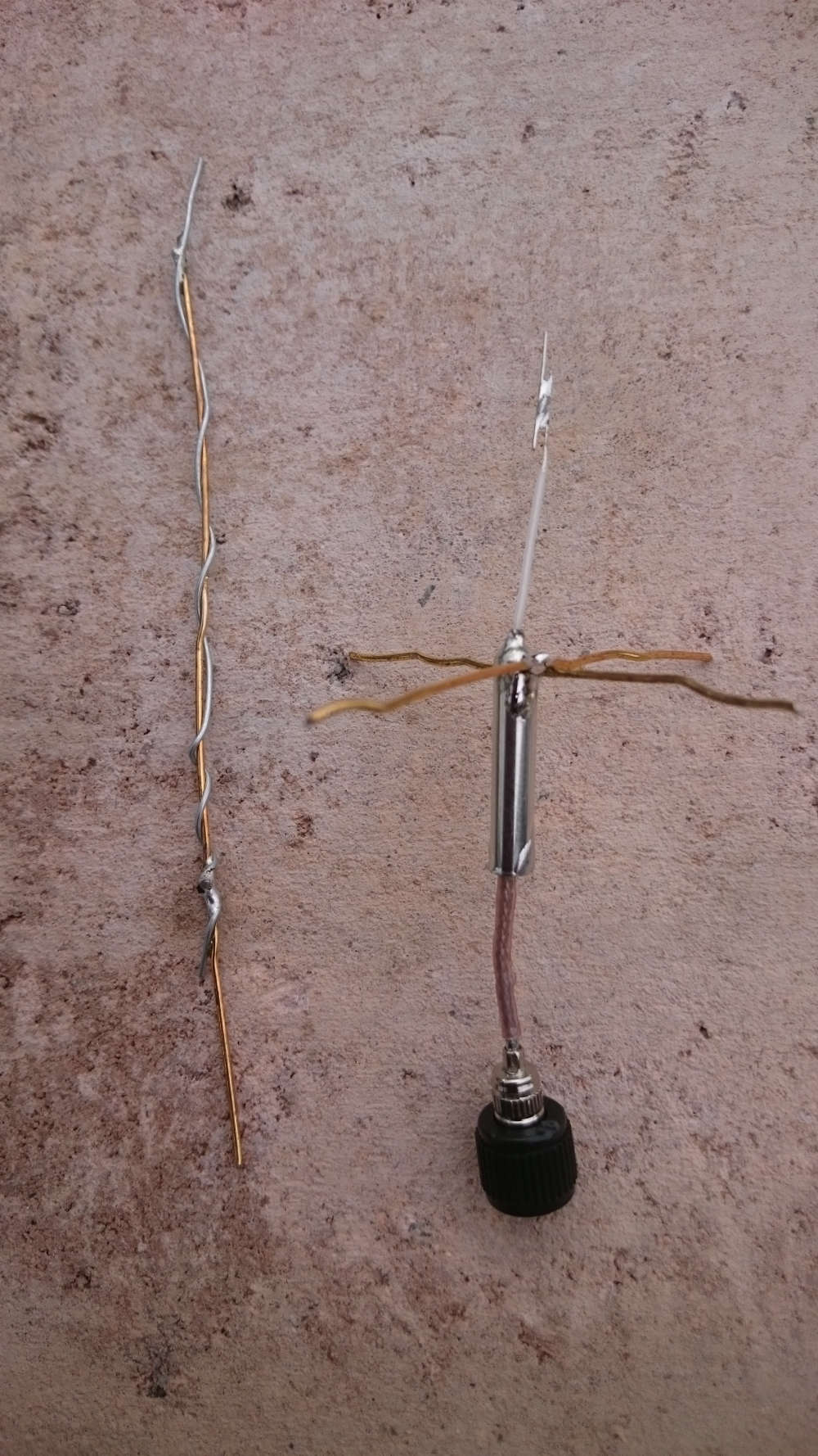
I decided to look inside the antenna:
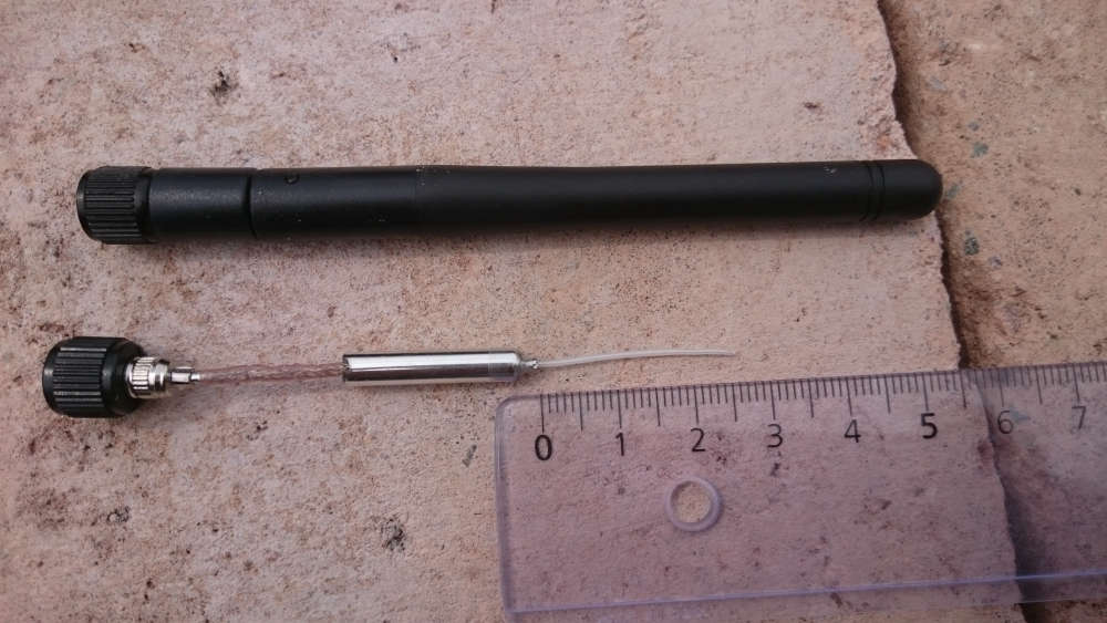
As you see above, it starts with an antenna cable that leads to a half wave dipole (where the antenna element is of about 1/4 wave length) and there is a "sleeve balun" going back over the cable . I can find no ground plane though. The problem that I can see is that the antenna length is 27 mm where it should optimally be 28.8 mm.
Now, if I remove the antenna completely my node works quite well. At least better than if I use the original antenna unmodified.
If I insert a wire (DIY antenna made by a paper clip) extending 121 mm out of the antenna sockets forming a full wave length antenna things work great.
I also modified the original antenna so that the antenna element becomes 28.8 mm. It works a bit better but it's far from perfect and communication errors are shown in the log.
As the final test, I added a nice ground plane to the original antenna and now it works really perfect!
So what can I learn from this?
My test rig is an EasyPCB powered with batteries. I'm quite sure that my NRF24L01+PA+LNA module used in another scenario, for example connected to a Arduino Nano fed by a FTDI connector could actually work. It's because it would create a different environment. The antenna will work in relation to what it's connected to, shielding the grounding, and surrounding objects. Capacitive and inductive reactances are involved in mysterious ways.
Anyway. My conclusion is that the two original antennas I have are not working very good. They obviously have the wrong length just a little bit, and I'd say that the the way the antenna is constructed with the sleeve balun and no ground plane, doesn't seem to work well. At least not here.
I'll do some more experimenting with making my own antennas. Starting with taking apart an original antenna is not so bad, I can solder anything (solderable) onto the cable.
Cheers!
From wikipedia:
Sleeve balun
At VHF frequencies, a sleeve balun can also be built to remove feeder radiation.Another narrow-band design is to use a λ/4 length of metal pipe. The coaxial cable is placed inside the pipe; at one end the braid is wired to the pipe while at the other end no connection is made to the pipe. The balanced end of this balun is at the end where no connection is made to the pipe. The λ/4 conductor acts as a transformer, converting the zero impedance at the short to the braid into an infinite impedance at the open end. This infinite impedance at the open end of the pipe prevents current flowing into the outer coax formed by the outside of the inner coax shield and the pipe, forcing the current to remain in the inside coax.
Hello! It looks like you're interested in this conversation, but you don't have an account yet.
Getting fed up of having to scroll through the same posts each visit? When you register for an account, you'll always come back to exactly where you were before, and choose to be notified of new replies (either via email, or push notification). You'll also be able to save bookmarks and upvote posts to show your appreciation to other community members.
With your input, this post could be even better 💗
Register Login