Which Lab Power Supply?
-
I am really considering this one:
EEVBlog has a little write up about it. It has a fan but it is variable and they say it is quite:
http://www.eevblog.com/forum/testgear/inside-the-new-korad-ka3305p-linear-psu/
-
What are the benefits of software controlled PSU versus turn-knob style?
-
on a sw controlled, you could have memories for the different voltages that you usually work with (for me that's 3V3, and 5V). Just a single press of a button to set the desired output voltage..
Other than that, I don't see any advantages..
-
It it is software controlled, you could also script things. Useful for testing stuff. Rough emulation of battery powered behavior and such.
-
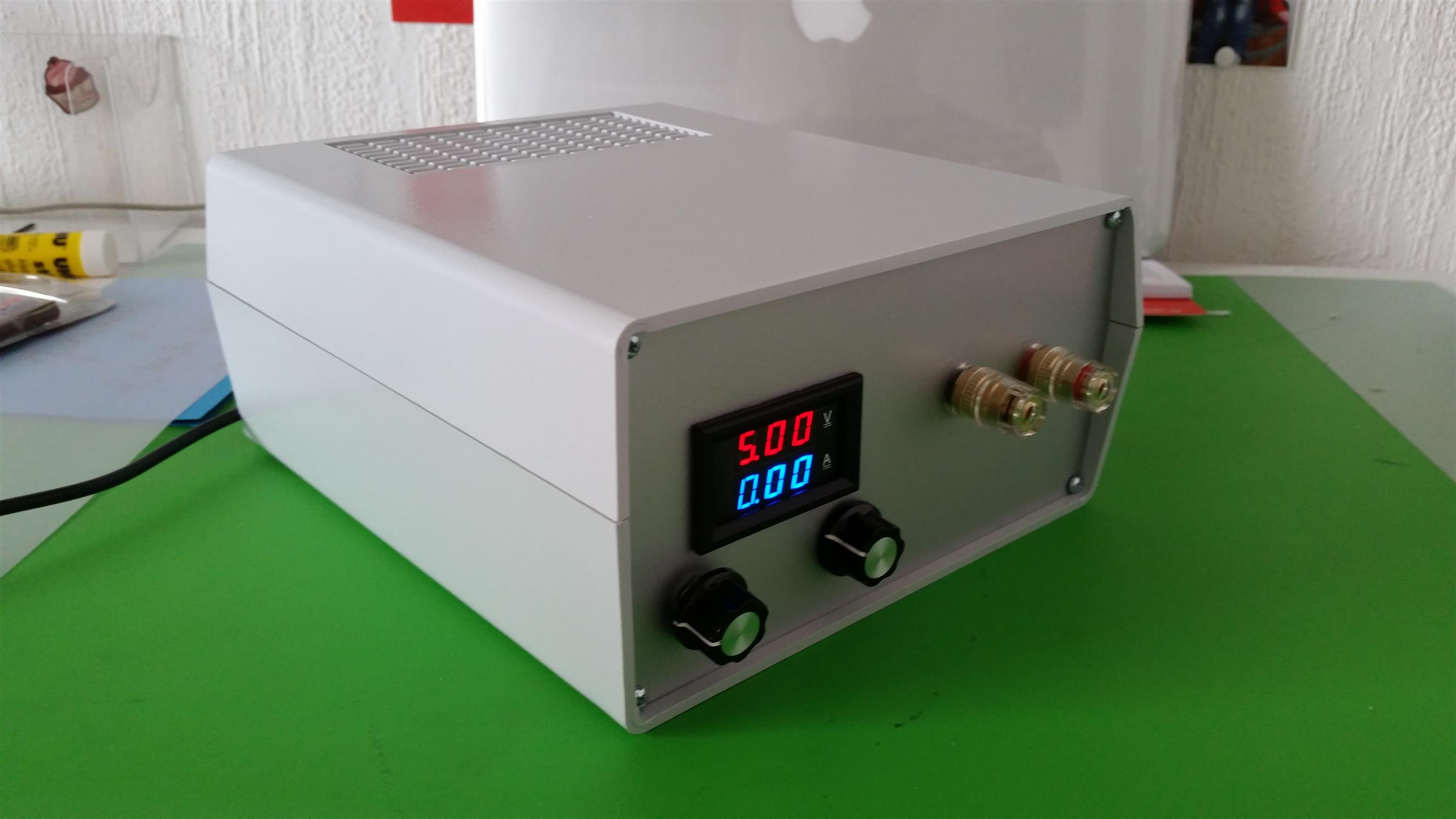
Just buy a LTC3780 (link), exchange the pots, hook up a volt/amp display and there you have it: your own lab power supply which can deliver 1V-30V // 0A - 8A, 10A peak.
Here's mine:
-
Just buy a LTC3780 (link), exchange the pots, hook up a volt/amp display and there you have it: your own lab power supply which can deliver 1V-30V // 0A - 8A, 10A peak.
Here's mine:
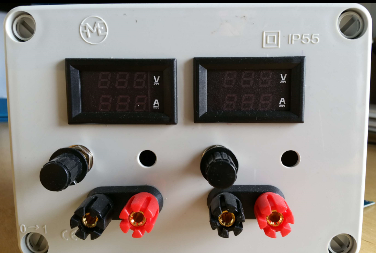
@HenryWhite Looks good. I did something similar (not completely finished) but went too cheap ;-(
A huge (0.3 V) noise/ripple on the output.... Are you able to measure the ripple with the converter you used? And what kind of transformer did you use? -
@HenryWhite Looks good. I did something similar (not completely finished) but went too cheap ;-(
A huge (0.3 V) noise/ripple on the output.... Are you able to measure the ripple with the converter you used? And what kind of transformer did you use?@AWI said:
@HenryWhite Looks good. I did something similar (not completely finished) but went too cheap ;-(
Looks good too!
A huge (0.3 V) noise/ripple on the output.... Are you able to measure the ripple with the converter you used? And what kind of transformer did you use?
I can't measure it, because I don't have an oscilloscope (yet) :smile:
For powering the module, I used an old 12V laptop power supply. -
Any thoughts on a case (ebay/ali) for homemade PSUs?
-
@HenryWhite Looks good. I did something similar (not completely finished) but went too cheap ;-(
A huge (0.3 V) noise/ripple on the output.... Are you able to measure the ripple with the converter you used? And what kind of transformer did you use? -
@AWI , a did a similar thing, but never got the volt/amper meter work properly on the 'negative side'. Mine looks very similar (to not say identical) to yours... Would you mind to share how did you connected the V-A meters?
@rvendrame As far as I remember there are two similar power positive voltage (isolated) power supplies with the meter in the positive line. Then connect the positive line of no 1 to the negative line of no 2.
Hello! It looks like you're interested in this conversation, but you don't have an account yet.
Getting fed up of having to scroll through the same posts each visit? When you register for an account, you'll always come back to exactly where you were before, and choose to be notified of new replies (either via email, or push notification). You'll also be able to save bookmarks and upvote posts to show your appreciation to other community members.
With your input, this post could be even better 💗
Register Login