Skip to content
  • MySensors
  • OpenHardware.io
  • Categories
  • Recent
  • Tags
  • Popular
Skins
  • Light
  • Brite
  • Cerulean
  • Cosmo
  • Flatly
  • Journal
  • Litera
  • Lumen
  • Lux
  • Materia
  • Minty
  • Morph
  • Pulse
  • Sandstone
  • Simplex
  • Sketchy
  • Spacelab
  • United
  • Yeti
  • Zephyr
  • Dark
  • Cyborg
  • Darkly
  • Quartz
  • Slate
  • Solar
  • Superhero
  • Vapor

  • Default (No Skin)
  • No Skin
Collapse
Brand Logo
  1. Home
  2. My Project
  3. Slim Node 5V-Mod

Slim Node 5V-Mod

Scheduled Pinned Locked Moved My Project
17 Posts 7 Posters 5.9k Views 8 Watching
  • Oldest to Newest
  • Newest to Oldest
  • Most Votes
Reply
  • Reply as topic
Log in to reply
This topic has been deleted. Only users with topic management privileges can see it.
  • ahmedadelhosniA Offline
    ahmedadelhosniA Offline
    ahmedadelhosni
    wrote on last edited by
    #4

    @Soloam said:

    w I'm asking for your help to see it an

    Great design and idea.

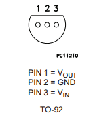
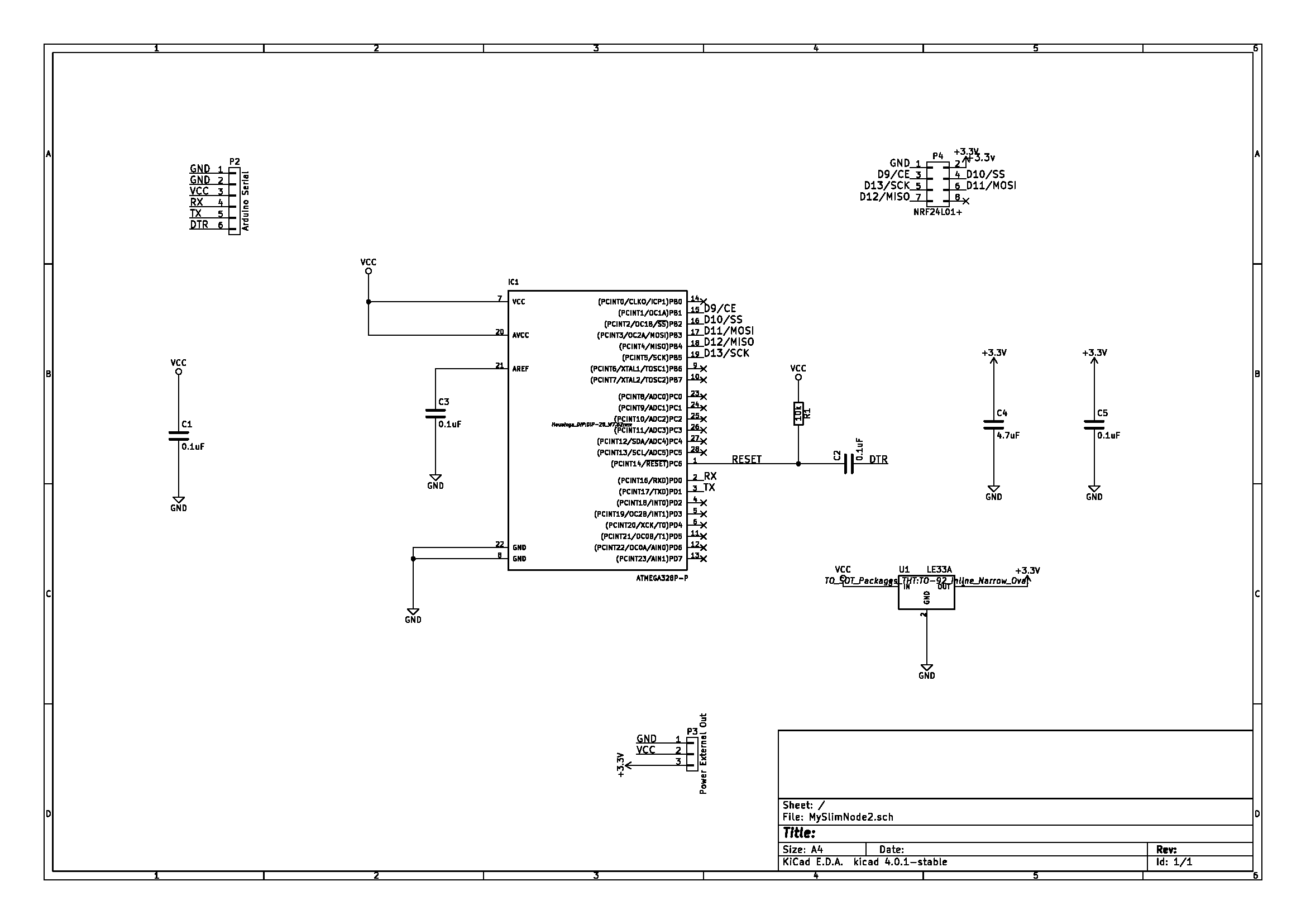
    I was replying that everything is okay until I decided to have another look. Did you switch the regulator Input and the Output ? from this reference :

    0_1460660870931_upload-3cd31042-5756-4443-a03b-7f4f1bee430b

    The L in your layout shall be PIN3 which is Vin according to the above picture, and vice versa.

    Can you please post your schemtatic. Maybe I am confused.

    1 Reply Last reply
    0
    • ahmedadelhosniA Offline
      ahmedadelhosniA Offline
      ahmedadelhosni
      wrote on last edited by
      #5

      I was also going to refer to the thin pcb traces in the design. I haven't used KiCad yet so I don't know the default, but 10 mils is enough in our designs for a normal signal, and maybe 16 mils for Vcc and Gnd ( which is also a lot in my opinion as we don't draw a lot of current in our designs)

      1 Reply Last reply
      0
      • scalzS Offline
        scalzS Offline
        scalz
        Hardware Contributor
        wrote on last edited by scalz
        #6

        I agree too for traces. and for instance some fabhouse has a 6mil trace min but often says 8mil is recommended. So if you don't want to have broken trace during pcb fab process, it's better 8mil min or 10mil is nice, for signals ;) For below, it's premium pcb, more expensive better quality..
        I have already used 8mil because it was compact, worked ok, but 12 or 10mil is usually my setting. and for power..16 to 20mils, it depends where..lol :)

        1 Reply Last reply
        0
        • SoloamS Offline
          SoloamS Offline
          Soloam
          Hardware Contributor
          wrote on last edited by Soloam
          #7

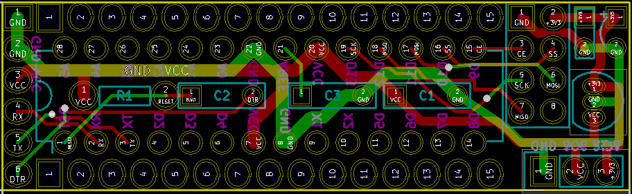
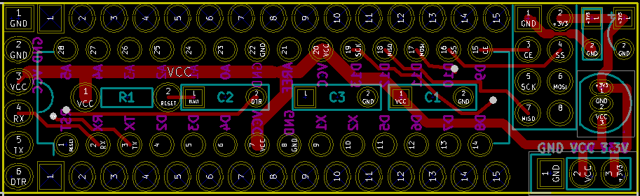
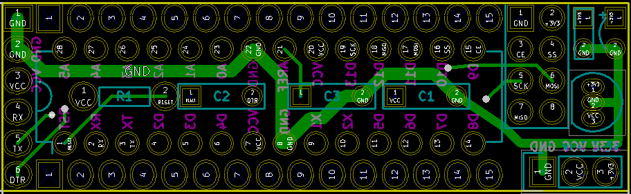
          Hi all, thank you for the replays, this is the first time that I use KiCat, so I used @m26872 design as a start up! For what I can see, the VCC and GND traces are 1,000mm and the signal traces 0,250 mm! Is it good? Not lots room in the PCB! I'll post better images, the ones that I've included are very low resolution!

          @ahmedadelhosni I think you are right, I've seen an image online and this was the layout, but now I've been looking at the datasheet (noob mistake) and I think that I missed them out! Tomorrow I'll assemble the test circuit and test it out!

          Thank you all

          1 Reply Last reply
          0
          • SoloamS Offline
            SoloamS Offline
            Soloam
            Hardware Contributor
            wrote on last edited by
            #8

            Main post updated, I'll validate the LE33 pin layout tomorow and post back!

            1 Reply Last reply
            0
            • m26872M Offline
              m26872M Offline
              m26872
              Hardware Contributor
              wrote on last edited by
              #9

              If you read through the connect radio - build site old comments you'll see that I've validated the labeled LE33 image posted there. If it turns out to be wrong again, please notify.

              1 Reply Last reply
              1
              • GertSandersG Offline
                GertSandersG Offline
                GertSanders
                Hardware Contributor
                wrote on last edited by
                #10

                Looking at the schematic, this should work fine.

                1 Reply Last reply
                0
                • SoloamS Soloam

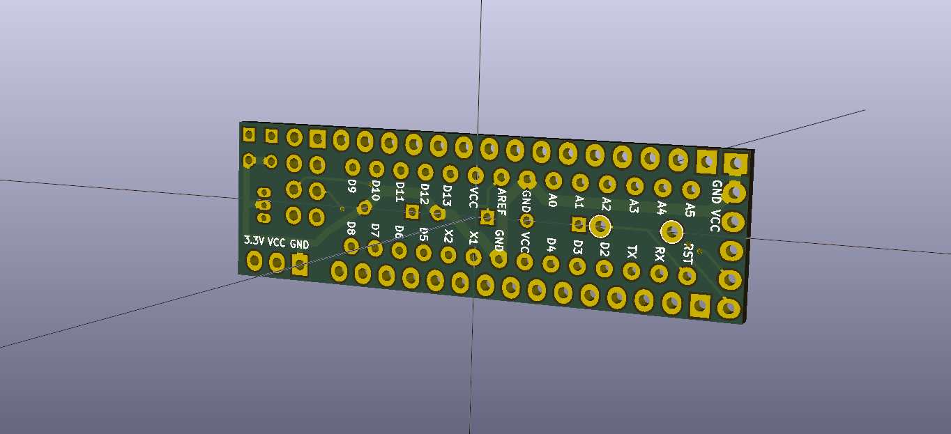
                  Hello all, I've been using m26872 slim node to some of my nodes, but my main problem was not being able to power it with 5V because the RF is only 3.3v. So I made some modifications to the design and now I'm asking for your help to see it and validate it! I'm no expert in electronics (not at all) and this is my first attempt with KiCat.

                  The main idea is to power the Radio with a LE33A step down regulator! Here is the result:
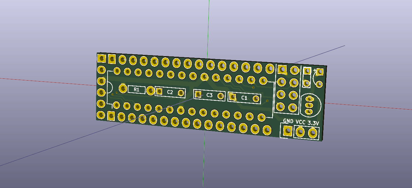
                  0_1460679098776_all.png
                  1_1460679113954_front.png
                  0_1460679113951_back.png

                  1_1460679132609_front3d.png
                  0_1460679132609_back3d.png

                  1_1460679153850_print.pdf
                  0_1460679153850_image.png

                  BOM
                  C1,C2,C3 : 0.1uF capacitor P-5mm (low to fit inside IC1 socket)
                  C5 : 0.1uF capacitor P-2.5mm
                  IC1 : Atmega328p
                  R1 : 10k resistor 1/4W
                  P4 : nRF24L01+
                  U1: LE33A

                  What do you think, will it work? My main concern is the Capacitors!

                  Thank you all.
                  Best Regards

                  PS: Credits and tanks to @m26872 for the base design and help

                  AWIA Offline
                  AWIA Offline
                  AWI
                  Hero Member
                  wrote on last edited by
                  #11

                  @Soloam Any specific reason to use LE33A? The quiescent current of this LDO is typ. between 0.5 (no load) and 1.5 mA . Unless you are using a > 6 V input voltage I would suggest using the 662K. Can be soldered by (a stable) hand, small footprint, very cheap and quiescent current of only 1 uA (typ.).

                  m26872M 1 Reply Last reply
                  3
                  • AWIA AWI

                    @Soloam Any specific reason to use LE33A? The quiescent current of this LDO is typ. between 0.5 (no load) and 1.5 mA . Unless you are using a > 6 V input voltage I would suggest using the 662K. Can be soldered by (a stable) hand, small footprint, very cheap and quiescent current of only 1 uA (typ.).

                    m26872M Offline
                    m26872M Offline
                    m26872
                    Hardware Contributor
                    wrote on last edited by
                    #12

                    @AWI - the notorious SMD-free concept violator - :wink:

                    AWIA 1 Reply Last reply
                    1
                    • m26872M m26872

                      @AWI - the notorious SMD-free concept violator - :wink:

                      AWIA Offline
                      AWIA Offline
                      AWI
                      Hero Member
                      wrote on last edited by
                      #13

                      @m26872 ouch.. :grinning: ok, a to-92 alternative MPC1700

                      But why drill holes...

                      1 Reply Last reply
                      2
                      • SoloamS Offline
                        SoloamS Offline
                        Soloam
                        Hardware Contributor
                        wrote on last edited by
                        #14

                        @SMD is a lot harder to solder, I prefere this one :)

                        I checked the LE33 and my layout is correct, that is the correct way to put it!

                        1 Reply Last reply
                        0
                        • SoloamS Offline
                          SoloamS Offline
                          Soloam
                          Hardware Contributor
                          wrote on last edited by
                          #15

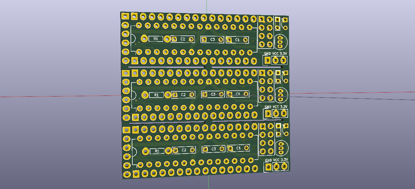
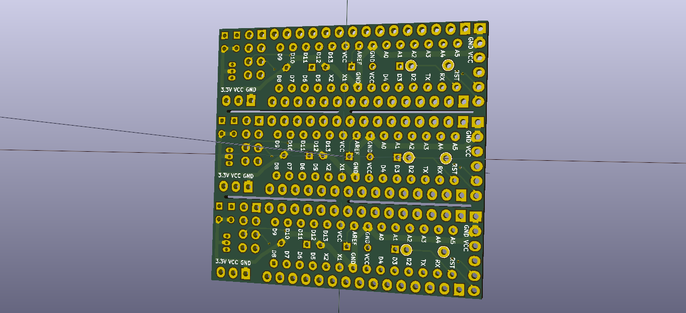
                          Hi all! I have merged 3 boards into one 50x50 layout, this way I can send it to print in dirtypcbs.com and order 10 pcb's, that will make 30 nodes! The solution is similar to the one used by @m26872

                          1_1460985222842_merged_front.png 0_1460985222842_merged_back.png

                          1 Reply Last reply
                          3
                          • SoloamS Offline
                            SoloamS Offline
                            Soloam
                            Hardware Contributor
                            wrote on last edited by Soloam
                            #16

                            Order submitted, now I just need to wait for the arrival!

                            I started also a new project that will control my light switches.

                            https://www.openhardware.io/view/83

                            badmannenB 1 Reply Last reply
                            0
                            • SoloamS Soloam

                              Order submitted, now I just need to wait for the arrival!

                              I started also a new project that will control my light switches.

                              https://www.openhardware.io/view/83

                              badmannenB Offline
                              badmannenB Offline
                              badmannen
                              wrote on last edited by
                              #17

                              @Soloam
                              Hello looks like a great board. Any progress on the Switch board?

                              //Henrik

                              rPi 3 - UNO R3 - Mini - Nano - custom

                              1 Reply Last reply
                              0
                              Reply
                              • Reply as topic
                              Log in to reply
                              • Oldest to Newest
                              • Newest to Oldest
                              • Most Votes


                              18

                              Online

                              11.7k

                              Users

                              11.2k

                              Topics

                              113.0k

                              Posts


                              Copyright 2019 TBD   |   Forum Guidelines   |   Privacy Policy   |   Terms of Service
                              • Login

                              • Don't have an account? Register

                              • Login or register to search.
                              • First post
                                Last post
                              0
                              • MySensors
                              • OpenHardware.io
                              • Categories
                              • Recent
                              • Tags
                              • Popular