Homini Complete Room Sensor Module?


  • Hardware Contributor

    cool, I think you will get this sensor working...even if now you don't need all these advice, maybe in future you will remember about it when needed 😉
    humm, maybe at lunch I will try to make a basic and small childboard for this one..so I will be able to add it to my pir multisensors..very tempting, and so I would be able to help you..


  • Hardware Contributor

    @scalz Oh, no doubt about it i need this advice and i thank you for it. I definitely need it as i wouldn't be asking here 😉

    From my findings i need a fair bit of help on the sensors them selves and their calibrations too.

    A daughter board for which board? I'm intrigued to see what you come up with. I'm planning on having this split in two boards stacked on top of each other inside of the enclosure. One for power distribution and one for data and sensor connections.


  • Hardware Contributor

    👍 Gas/Smoke/Temp/Hum/Light/Motion in one would be great!
    For me its tempting when you are aiming at a celing mounter 3d case like a smoke detector.

    I hope it can all be fitted inside a normal size case - you see, there are other aspects of it like esthetics according to my wife.


  • Hardware Contributor

    @sundberg84, i'm with your wife here. It must look appealing to the eye, hense why i wanted in a custom enclosure fashioned like that smoke detector/sprinkler image i included. Since its something being mounted on the ceiling, its got to be subtle and not in your face ugly.

    I'm glad you're very interested in following this production, thank you 👍


  • Hardware Contributor

    @sundberg84 nice catch 🙂
    @Samuel235 : this one (I showed you in post above) http://forum.mysensors.org/topic/2951/my-mysx-multisensors-board
    On daughter board, the sensor would be on the left side of the pic because others sensors are on right (little dirty hack but like this I could have everything I need per room..depending of the sketch size too). I would add mosfet to cut power on daughterboard etc...a thing to try, I just need to make a tiny daughter board, oshpark and voila!


  • Hardware Contributor

    @scalz, ahh sorry i forgot you linked that. Yeah that would make that a nice little setup!


  • Hardware Contributor

    @Samuel235 : here what could look my small childboard...first pass, I will change few things before order it. 3.35$ for 3 boards at oshpark 🙂 It could be smaller, it is because now I like/try to have everything ontop (but there are two smd jumpers on bottom), that made me hungry! time to eat 🙂
    @tbowmo: here an idea for a childboard 😉
    0_1458735075418_2016-03-23_13-08-18.png


  • Hardware Contributor

    @scalz I like it! A quick side step, how do you make these 3D models? Are they generated by your eagle designs or do you manually build them in a 3d model program?


  • Hardware Contributor

    @Samuel235 thx. actually, I still use eagle 6.5, I know there are things in 7.x but not tried yet. so for the moment, sometimes I make my own model, or find some where I can..for 3d preview, google sketchup eagleup. So for pcb preview I use sketchup, for custom enclosure solidworks (I prefer it than sketchup) then I export box to sketchup (as I can't do the opposite). Have fun 🙂


  • Hardware Contributor

    @scalz, thank you. I'll spend many hours playing now 😉


  • Admin

    @scalz

    Nice 🙂 I'm preparing a board with various sensor types on, that one could populate as one wishes..


  • Hardware Contributor

    @tbowmo, cool! Be sure to include the information or links in here for us to check out please 🙂


  • Admin

    @Samuel235

    It would be added as a MysX add-on module (have some space left on a panel, that I'm preparing)


  • Hardware Contributor

    @tbowmo now i'm even more intrigued 🤔


  • Hardware Contributor

    I'm still on the man hunt for the right sensor to use for air quality, I've narrowed my search down to two parameters to monitor; Carbon Monoxide and Smoke. If you guys would like to see any other gases being monitored please give me your feedback, this is all that i would want, but i have no idea of the other countries and their interests to gases. What about carbon dioxide?

    So i have roughly chosen two sensors, the CCS801 for Carbon Monoxide and the MP503 for Smoke. I know there are a few sensors out there for smoke and to be honest, i'm yet to study those in comparison to the MP503 due to being very busy at the moment. Could anyone give any input on my choices here and if i should use another sensor out of the MP range from Winsen-Sensors for my smoke one? What about the Carbon Monoxide choice, that look good enough for you guys?

    CCS801 - Carbon Monoxide:
    Power Consumption: 1.8v 0.9mW (In pulse mode)
    Rough Price without shipping costs: £5.49
    Datasheet: http://www.ccmoss.com/sites/default/files/documents/CC-000015-DS-8-Datasheet for CCS801.pdf

    MP503 - Smoke:
    Power Consumption: 5v <300mW
    Rough Price without shipping costs: £N/A at the moment
    Datasheet: file:///C:/Users/Desktop%20System/Downloads/MP503%20(Ver1.4)%20-%20Manual.pdf


  • Hardware Contributor

    Sensor Choice

    From further research, I have learnt that there are two main types of sensors out there; electrochemical and semiconductor. The information displayed below explaining each are extracts from Wikiedia.

    Electrochemical:
    Electrochemical gas detectors work by allowing gases to diffuse through a porous membrane to an electrode where it is either chemically oxidized or reduced. The amount of current produced is determined by how much of the gas is oxidized at the electrode,[3] indicating the concentration of the gas. Manufactures can customize electrochemical gas detectors by changing the porous barrier to allow for the detection of a certain gas concentration range. Also, since the diffusion barrier is a physical/mechanical barrier, the detector tended to be more stable and reliable over the sensor's duration and thus required less maintenance than other early detector technologies.

    However, the sensors are subject to corrosive elements or chemical contamination and may last only 1–2 years before a replacement is required. Electrochemical gas detectors are used in a wide variety of environments such as refineries, gas turbines, chemical plants, underground gas storage facilities, and more.

    Semiconductor:
    Semiconductor sensors detect gases by a chemical reaction that takes place when the gas comes in direct contact with the sensor. Tin dioxide is the most common material used in semiconductor sensors, and the electrical resistance in the sensor is decreased when it comes in contact with the monitored gas. The resistance of the tin dioxide is typically around 50 kΩ in air but can drop to around 3.5 kΩ in the presence of 1% methane. This change in resistance is used to calculate the gas concentration. Semiconductor sensors are commonly used to detect hydrogen, oxygen, alcohol vapor, and harmful gases such as carbon monoxide. One of the most common uses for semiconductor sensors is in carbon monoxide sensors. They are also used in breathalyzers. Because the sensor must come in contact with the gas to detect it, semiconductor sensors work over a smaller distance than infrared point or ultrasonic detectors.

    So while the electrochemical is the better of the two in terms of power consumption, they do required to be changed on average every 2 years. However, while that is a downside, you do have to re-calibrate the semiconductor type if its needed to remain the accuracy it did when installed. I'm not sure which would be better, to replace or to re-calibrate? One side of the argument is that the semiconductor range is much easily available, at least for the UK market anyway, and cheaper to purchase. But then you have the power consumption of the internal heater to consider, they reportedly get up to anywhere in the region of 60 degrees Celsius, this would cause issues for my temperature sensor (unless i some how shield my temp sensor off from the area of the gas sensors, possible to do with a custom enclosure.


    I'm proposing that if we wanted to go down the route of the electrochemical sensors, we could mount these on daughter boards and mount these either ribbon cables or pin headers to then enable us to swap out the sensors with ease in the future. I'm tempted with the idea of having the daughter board that holds the sensor externally accessible, but inside its own enclosure that attaches to the main enclosure so you would just pull off a side enclosure and either replace the whole thing or replace the sensor board inside of this side enclosure and then push the side enclosure back onto the main enclosure. Interesting prospect. By the time I get some feedback i might be able to use a 3d modeler to possibly mock up some 3d sketches of what i mean.

    But then the semiconductor type is a simple calibration using a 'calibration test' that you purchase from the manufacturers and adjust to meet the known concentration of the given gas. This can take several days depending on the heat-up time. I do not like the sound of this. The whole idea of this module is to be ease of use and to leave it running on its own without worrying about if its accurate or not.

    Current Thoughts

    As you can see i'm really starting to favor the low power, high cost, hard to find electrochemical sensors. However, like I've stated many times over, they're proving very hard to get my hands on. If anyone knows of any, please link them in here.

    What're your thoughts on the sensing sides of things, would you rather:

    1. Low component cost, higher running costs, higher maintenance. Electrochemical.
    2. High component cost, low running costs, possible high maintenance. Semiconductor.

  • Hardware Contributor

    Due to the electrochemical sensors being so hard to get my hands on it would seem i have very little choice but to order off of AliExpress.

    I have found a decent price for the ME2-CO here: AliExpress.

    I'm very tempted to get some normal MQ-7's just to try them out or even the high quality Figaro TGS2442's, but i just don't like the 24-48 Hour warm up period on those, that coupled with the power consumption is just putting me off of the 'normal' Semiconductor types. However, they are pretty cheap compared to the Electrochemicals.

    Datasheets:

    ME2-CO
    MQ-7
    TGS2442

    Questions

    1. Could i get some of your opinions on this, do you feel i'm being a little over the top with the power consumption issue?
    2. Whats your thoughts on the warm-up times? Don't forget they do apply when it comes to calibrating the sensor, you would have to make the calibration alterations, then wait another 2 days for it to warm and settle before testing again....

  • Hardware Contributor

    I've nearly compiled the full list of sensors for this module as follows:

    I'm now left with sourcing a low cost buzzer for this module and some LED's for status updates for debugging and notifications of working states. I'm tempted to have the device sleep with the smoke and carbon monoxide sensors connected to interrupt pins if possible and only have the motion sensor detecting in certain situations such as night time and alarm enabled status maybe. Its not something i want on permanently if not needed due to the current usage in busy areas such as hallways and main rooms, it will draw power consistently and the idea is to keep the power consumption down as low as possible.

    As usual I appreciate all thoughts and suggestions for this and welcome them to the comments. I'm not the best at software/coding so if anyone would like to help in that aspect, i wouldn't say no when the time comes to do such a task. It will be a few weeks before that happens though as i'm yet to design the hardware. I need to purchase a few tools before this can go a head, including a hot air reflow station and a 3D printer for the custom case.


  • Hardware Contributor

    With all the parts for this module on order now, just for a discussion;

    1. What would you hardware guys rather have in terms of ambient light sensors? Digital (I2C device) or Analogue that performs like a NPN transistor? What is easier to configure/setup? (APDS-9300-020 OR TEMT6000X01)

    2. Low power motion detector daughter board or HC-SR501 Module?

    3. I'm yet to make my voltage supply schematic, i'm looking at a few topics around here regarding this, does anyone have any information to educate me further in this area, power supply is not my most confident area 😉


  • Hardware Contributor

    Smoke Detector

    I do plan on having footprints for both of the smoke detection methods, but this all depends on the space allowed on the PCB. If I can't have the footprint for both I will be making designs for both variations. On both of the designs, they will use the temperature sensor to create a 'hybrid' type of smoke detector so it isn't just smoke that it has to detect to trigger the fire warning.

    Optical/Photoelectrical Method

    I'm going down the route of creating my own optical sensor simply because I can not source a enclosed solution to put into my module. The only way around this would be to purchase cheap optical smoke detectors and remove the module and apply it to mine. Rather than doing this I would rather attempt to create my own solution using a IR Emitter LED and a IR Receiver.

    However, to do this I need to have the IR LED pulsing at 38KHz. So this is where I'm feeling a 555 timer to come into play. Now I haven't done my research on a 555 timer but from what i understand the capacitor in the 555 circuit instructs the timer on the length of time the LED needs to be enabled, so this is what creates the 38KHz pulse. Please instruct me if I have this wrong. I'm then thinking that I could just monitor for smoke every 10 seconds or so to try and lower the consumption again. To do this would I just need to switch the trigger pin from low to high to make the output turn off therefor turning the LED off and then pull the trigger pin low to then turn the LED back on?

    Ionisation Method

    I'm very tempted to just use a MQ2 sensor with its circuit on my board rather than a separate board.


  • Hardware Contributor

    Motion Detection

    Would you guys rather the motion detection be connected via a transistor so we can send messages to the node to enable and disable the motion side of the module rather than having motion being detected at all times? This isn't to save power (like a few of you that know me would assume) but more to enable us to only have it enabled at night in 'night time' mode to stop it from being triggered and sending messages back to the gateway constantly through every day life, in the main rooms of the house.

    Look forward to hearing your inputs.


  • @Samuel235 said:

    Motion Detection

    Would you guys rather the motion detection be connected via a transistor so we can send messages to the node to enable and disable the motion side of the module rather than having motion being detected at all times?.

    If not to save power, would not a software solution be easier and less complicated solution?


  • Hardware Contributor

    @Dwalt said:

    @Samuel235 said:

    Motion Detection

    Would you guys rather the motion detection be connected via a transistor so we can send messages to the node to enable and disable the motion side of the module rather than having motion being detected at all times?.

    If not to save power, would not a software solution be easier and less complicated solution?

    You're correct in this scenario, however i've since decided to brong the power consumption as low as i can physically for two reasons; to bring the running costs of the module down as low as possible snd to allow me to adapt this board for use with batteries if ever it needed to.


  • @Samuel235
    I was under the assumption you intended this module to be always 'listening' to allow a controller to set it to night mode or 'disarm'. If so, battery power will be tricky. In addition, PIRs require a period of stabilization when powered on, often up to 30 seconds to calibrate sensor field of view background.


  • Hardware Contributor

    @Dwalt, you're right with the intention is to be listening all the time, and then therefor it would mean that sleeping the node for battery power is not going to work. However, i was planning to do this as a backup solution and then for incase i needed the feature. If this was needed to go to battery power it was able to switch off the motionI probably wont ever have a need for it, but its there if needed.

    To go a step futher i could find a PIR Control IC, i remember reading somewhere that a fee controllers allow a PIR Sensor to be active when not even powered up. I might be wrong here but either way i understand your information regarding a warm up time on the motion module.

    Thank you.


  • Hardware Contributor

    UPDATE

    So then guys. I feel I have the sensing side of the board all designed out, I will include a schematic here for you to see. Just due to my inexperience of electronics still, i'm sure there will be a few faults/things you guys would like me to change around. Please point anything of any concern out to my attention and i will amend accordingly.

    Sensors

    Light: OPT3001
    Motion: HC-SR501 Module
    Temperature & Humidity: SHT21
    Carbon Monoxide: TGS5042
    Smoke1: Custom Photoelectric Circuit
    Smoke2: MQ-2.

    The smoke sensors can both be fitted or one or the other. They will differ in applications, what area the module is being used in. They both detect different types of smoke/fires. I will included more detailed information on this for the release of the product.

    Powering

    I'm still yet to design the powering side of this, it will be 240VAC converted to 5VDC then regulated as and when needed. I Will include some way to externally power this module while we're programming it since it will draw more than i'm comfortable providing through a PC USB Socket. So there will be no VCC lines coming onto the board from the USB programmers, this way we can't cause any damage to your PC USB sockets/serial lines. I'm yet to work out the overall typical power consumption, which i do plan on calculating today so i can get the powering converters specified for the current needed.

    Prototyping

    If there is any pins left, currently have 5 pins (3 Analog and 2 Digital) left over, however i'm very tempted to have status LEDs on this module so therefor that will be 3 gone and will only leave possibly 2 empty analog pins. These will have VIAs located so we can use them for prototyping.

    By no means is this schematic anywhere near completion, there may be floating connections or missing components. Please point them out if so.
    Excuse the unfinished power circuit at the top of the schematic, this is where i've got to so far before i ran out of time. Currently just placed the varistor and the AC/DC Converter. Will keep updating as and when time allows.

    0_1460927870597_HominiRoomDetectionSchematic.png


  • Hardware Contributor

    This post is deleted!

  • Hardware Contributor

    Updated the schematic in the post above. Please read the notes in bold above the image. Thanks.


  • Hardware Contributor

    Could i get some opinions regarding atmels signing IC's that we use for mysensor signing. Would you guys like this module to use that feature?

    I may need some external flash for OTA firmware updates but i'm not sure if i want to include this on Rev1, maybe this is a Rev2 upgrade.

    I doubt i will need any extra eeprom external from the amount built into the 328p mcu, we shall see about that when the software is made.

    Lastly, is there any additional features that you guys would like to see implimented onto this module that you feel is missing? Any errors so far with the schematic you can see?


  • Hardware Contributor

    Another little bit of progress. I'm really struggling with time at the moment, had another 15 minutes to get some schematics done today. The power circuitry is coming along now, just the external programming power to sort out.

    0_1461101334911_HominiRoomDetectionSchematic.png


  • Hardware Contributor

    And the first of many to arrive is the Figaro Carbon Monoxide sensor.

    0_1461139111942_image.jpeg


  • Hardware Contributor

    There is a topic (here) being discussed regarding the use of IR LEDs and receivers to determine the circuit needed before i get some hardware. I will be ordering parts before the end of this week so if there is no suggestions i will be purchasing materials to trial and test the best setup for this.

    Another subject to be discussed is powering while programming. I do propose to have the module fully powered up while programming and debugging to allow the monitoring of the sensor readings to allow debugging methods to be carried out with the best precision possible. However, this means that we need to have some sort of external connector on board to provide power while we're plugged into our programming systems. There would be two ways to go around this, one will allow full powered up mode for the board and the other will just allow power to the MCU and Radio while programming.

    1. Add external connector (I'm feeling maybe a USB Mini-B simply due to its popularity). This would then power up the board completely while programming is completed, allowing full debug viewing through serial monitor.
    2. Add a jumper on the power line of the MCU and Radio module to allow the programmer to provide enough power for the MCU and Radio while programming. This would mean that the only debugging we can do through the serial monitor would be MCU and Radio related.

    Any input would be greatly appreciated.


  • Hardware Contributor

    The remaining parts have been ordered to get the prototyping under way. Plan of attack will be:

    1. Prototype each circuit on breadboards separately to make sure each is working as intended and giving the correct results.
    2. Combine all of the circuitry apart from the powering options onto breadboard as one working module, get some software written up with the help of a few guides, tutorials and a fellow member of our community being interested in joining me on this module.
    3. Generate PCB designs and have them manufactured.
    4. Test the AC/DC conversion circuitry for a few weeks while the PCB is on order.
    5. Receive the PCBs and populate with the breadboarded circuit.
    6. Fashion some sort of enclosure, hoping to have purchased a 3d printer by then.

    Does anyone have any experience with a prusa I3 3d printer?


  • Hardware Contributor

    Infrared smoke detection circuitry has changed now. It is now going to running as a single IR LED coming from the MCU pin since we do not need any sort of frequency for a newly implemented photo transistor rather than the IR receiver. However, I may have it coming through the 555 time to just turn the LED on for 1 second every 10 seconds or so to stop excessive power draw for no reason. If it detects smoke 10 seconds later than it was first present inside of the chamber, that is fine for the needs of a smoke detector. In my opinion. If you feel otherwise please state so!

    I have chosen to do this outside of software to save having to do multitasking in software. This way all that the MCU needs to know is if the photo transistor has detected any smoke, which we can monitor on every loop of the MCU.

    I'm still not sure whether to go down the 555 timer route for the siren to sound or to use some soft of PWM function on the MCU. The way i'm thinking is that if we go down the timer route it releaves the MCU of another job and therefor it doesn't have to stall in the loop while its powering the buzzer. However, I personally feel that if the module detects smoke, the last thing that we will be worried about is if its taking readings from the other sensors. But then that would be a cool feature to be able to look back at the measurements on.


  • Hardware Contributor

    I would like to separate the 3v3 to the MCU and the radio from the rest of the components, this way i can safely power the MCU and Radio with the programmer when uploading software with just the programmer attached. But i want it so if it is powered externally i would like the board to use that power.

    I'm proposing the use of diode(s) on the power lines in between the MCU and radio to stop the flow going out to the rest of the circuit. I'm hoping that by using the diode(s) to stop the 3v3 from the programming feeding to the whole 3v3 circuit it will not draw enough current to damage the programmer and the PC. By using this diode i believe that the MCU and Radio will draw the strongest voltage of whatever is connected, if nothing is connected other than the FTDI or ISP programmer then it will only power on the MCU and Radio. A quick hand drawn sketch below:

    0_1461528748405_image.jpg

    Do you feel i'm going about this the correct way rather than separating the MCU and radio with a hardware jumper? One less thing to care about while programming in my opinion.


  • Hardware Contributor

    And the prototyping begins! Pretty much all of the breadboard versions of parts have arrived and i will be prototyping each circuit individually then wrapping it all together. A few mods need to be done to the light sensor to make it breadboard friendly but its doable!

    0_1461605119890_image.jpg


  • @Samuel235 Did you source a breakout version of the OPT3001? It is hard to find.


  • Hardware Contributor

    @Dwalt, unfortunately no mate, i will need to solder leads to the pads for prototyping needs 😞


  • Hardware Contributor

    @Dwalt, this is the one i was looking at but then decided to just solder leads to the sensor itself instead. If i were to get some breakout boards made and maybe solder the sensors on myself, i wonder what the demand would be like, just thinking if its worth doing to help us out.


  • Hardware Contributor

    @Samuel235
    wow, soldering leads on opt3001!
    That won't be easy I think, I hope you have very very thin wire and iron! and still not sure...it's a small 2mmx2mm, and delicate, I think you can easily skip this step, it's a simple i2c sensors, no surprise...or maybe you will waste some money if no good tools. I prefer to design evalboards than soldering leads on tiny dfn (doable sometimes but very tricky), it's easier to breadboard and reusable 😉

    @dwalt
    One thing I could do is to release some evalboards I have designed. As it's small, it's cheap at oshpark...I have already made one for opt3001, and have some for others sensors, boosters, buck, buckboost..but I'm little busy actually!
    But if I do this you would still have to solder it on pcb, or I should look at the new pcba service...


  • Hardware Contributor

    @scalz It seems you have beat me to it with creating a breadboard friendly breakout board for them. If you're confident in the use of this sensor could you double check my schematic and let me know if i have connected it correctly please?

    I might get a breakout board for breadboard friendly use designed if you're too busy yourself. Not sure how much call there is for them though.


  • Hardware Contributor

    @Samuel235 it's few months I did this. like I said I make breakout boards for testing, so I have a small collection now!
    This was a breakout with opt3001 and si7021, regulator onboard (with smd jumper to power directly with 3.3v), and few pullups. Same pinout as common chinese sensor boards + interrupt pin for ambiant light:
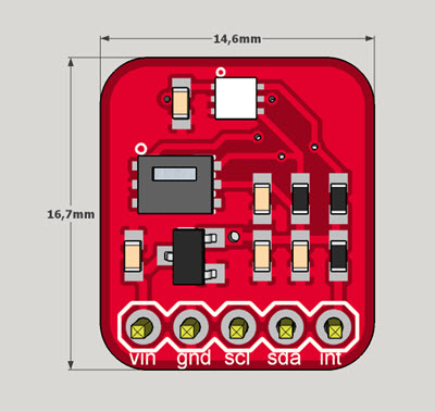
    0_1461670789062_opt3001si7021_break.jpg
    I will upload at openhardware asap 😉 that's lot of things to upload lol!


  • Hardware Contributor

    0_1462204198812_capturedvideo.MOV

    Currently prototyping the optical smoke sensor. I have the buzzer circuit working fine, i also have the circuitry for the optical sensor working. But i can't get it to reflect its IR Light off of smoke and onto the phototransistor.

    Waiting on some feedback regarding the Figaro sensor and using with a mosfet from another forum, will post updates when recieved.


  • Hardware Contributor

    UPDATE!

    Figaro TGS5042 Electrochemical Carbon Monoxide Sensor - Working.

    Prototype work complete for the carbon monoxide sensor, using the OP AMP style measurement system which includes just 1 Resistor, 1 Capacitor, an OP AMP (Model featured above) and the Sensor itself.

    Improvements?

    Currently reading through the appnotes given by Figaro for this sensor, heck its a long but interesting read! While it would be great to run with this current setup of 4 components for this circuit, there are things like polarity precautions on the sensor to be taken into consideration. So, with this being said, I'm currently in the process of maybe adding another OP AMP or just a resistor to the keep the sensor shorted out incase the device is isolated from power for any reason. Then there is the accuracy to take into account...

    Question

    I'm very tempted to amplify the sensors output enough to get to a PPM that is dangerous and then send the alarm off, meaning that at 5v out of the OP AMP it would be enough to send the sensor off and therefor we have a much a higher accuracy between safe and dangerous readings but it would not be able to go over what would be deemed as 'unsafe' levels. OR would you rather me have it so it can read to quite high CO levels despite the 'dangerous' level being around 2/3v out rather than 5v? So, would you rather a high range of readings but lower accuracy or a more accurate but lower range, still enough to detect the dangerous level?

    I will be posting images and schematics for the completed parts of the module ASAP for you guys to check out.


  • Hero Member

    @Samuel235 said:

    IONISATION METHOD

    I'm very tempted to just use a MQ2 sensor with its circuit on my board rather than a separate board.

    MQ2 consumes a lot of energy as every MQ. Also don't rely on your life on this kind of sensors...

    Have you tried the bottle of perfume around ?


  • Hardware Contributor

    @epierre, you're correct in thinking they are pretty high energy and inaccurate. Would you advise any other sensor at all for this method? I'm currently working on my own custom made optical smoke sensor unit using a IR LED and Phototransistor, but i would like a ionisation method sensor as well.


  • Hero Member

    @Samuel235 the ionisation for smoke ensor was the old method with radioactive elements.

    maybe a particle sensor but you would need to simulate a smoke to set levels, compared to a dusty room I think. Maybe a barbecue test (beware of greasy dusts !)


  • Hardware Contributor

    I'm encountering some issues regarding my MOSFET enabled PIR sensor. I'm currently using a n-channel MOSFET in a high side switching setup. The issues that i'm getting are that while the gate is pulled low, the sensor is alternating between a HIGH and LOW output, false triggering and when the gate is 5v, high, it is not powering at all.

    I'm attempting to get my hands on a p-channel MOSFET to put in a low side switching application to attempt to fix this. I'm assuming that its acting like this because its producing false triggers while the GND is not connected through to ground. I've tried to connect a 10k resistor from drain to gate to eradicate the 'floating' connection, no hope either. If anyone has a link to any p-channel MOSFET that i can get in the UK that would be much appreciated.


  • Hardware Contributor

    There is currently discussions going on over on the forums at allaboutcircuits.com with myself and a few others regarding this OP AMP and the sensor output readings. I thought i would let you guys know in case you're interested in following the build.


  • Hardware Contributor

    Once i have the smoke detection worked out and the carbon monoxide circuit more 'suited' i feel we're on the straight and narrow. Adding in things like signing, EEPROM, headers, temp sensors, is all easy and no configuration on the hardware level is needed. So over the next week or two i will be working to get the two sensors correctly working and optimized to the best suited adaptions with this device, then its a case of adding in any functionality that we feel is needed. I would like some feedback from you guys with what features you feel are appropriate for this module, EEPROM, Flash, signal LEDs, security signing, anything at all!
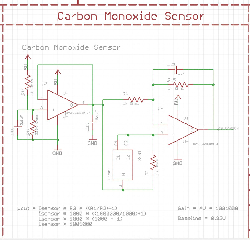

  • Hardware Contributor

    UPDATE!

    The sensor circuitry is now complete to give me a baseline voltage of 0.93V. This will allow for any variation in the sensor and the offset created by the op amp. I have used a double op amp system, the second op amp is performing a voltage follower role to remove any current interference from the voltage divider i have put in place to create the baseline to allow for errors to occur. The below schematic is for this section of the module. Getting close to getting the hardware side complete now. Just a few little things to iron out.

    0_1463234309085_SensorSchematic.jpg

    Currently completed hardware:

    Carbon Monoxide Sensor
    Motion Sensor
    Voltage Regulation
    Buzzer
    Radio
    Programming Headers

    Currently working on:

    Smoke Sensors (Optical and ionization, i may switch to particle detection though)
    Temperature
    Humidity
    Ambient Light
    AC Power connection
    DC Power connection

    Recommendations - Does anyone have anything else they would to see included onto this module?

    Atsha204 signing?
    External Flash?
    EEPROM?
    Status LEDs?


  • Hardware Contributor

    @Samuel235
    good job 😉 sorry for not being more active, actually busy 😕
    if you have things which needs security or "anti hacking" like pir for instance, I would add atsha. But it depends of pir usage too.
    Eeprom, as you want, but still useful.
    Led is always nice when you have enough room. for debug and indicators.
    I'm not sure if temp/hum sensor location is best at ceiling...during heating season, I think this is not representative of what we feel...but why not, perhaps in some case it can be useful. So, I prefer to have mine at the middle, not near a door or heater etc...
    humm, that make me think I need to hack my smoke sensors too..not done yet 😊


  • Hardware Contributor

    @scalz, I think i will be adding in what i can with the space, so i'll try and get it all included, EEPROM, ATSHA and if i have any pins left, i will get some debugging LEDs on, not holding my breath though.

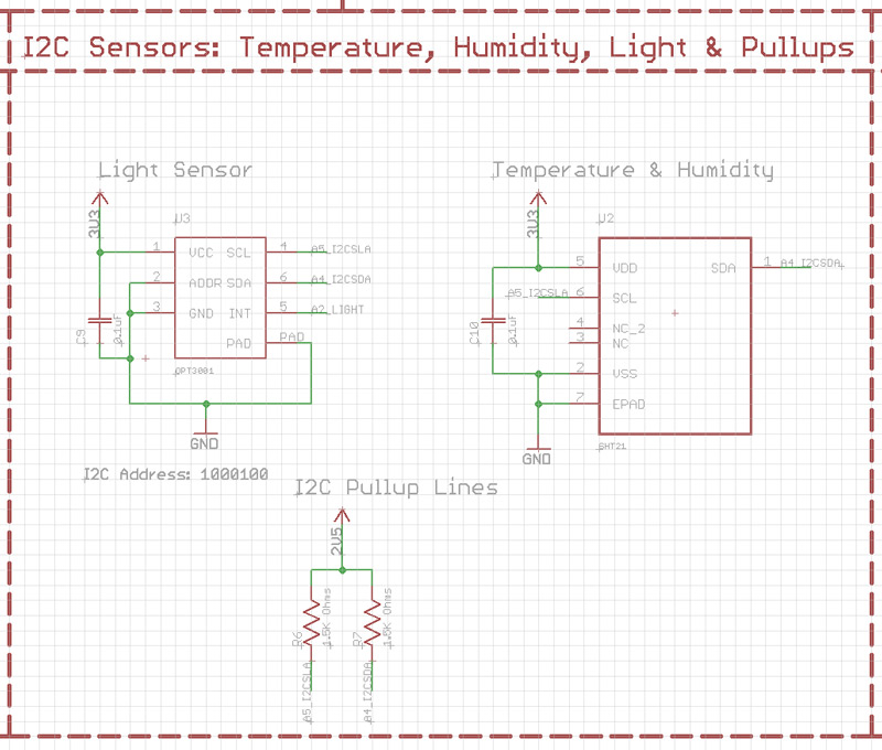
    As you have experience in using the I2C components i'm using here, could you have a quick look at the following at just let me know that they are okay and will not be conflicting on the I2C lines. I have looked into the addressing and i hope i have done accordingly.

    0_1463312857706_I2CSchematic.jpg

    If the Temp reading is completely off the accuracy due to its location i will just use it to compensate for the temp on the Carbon Monoxide sensor.


  • Hardware Contributor

    Because i'm clueless on the software sides of this, i'd like to ask someone from the @Code-Contributor group to give me their opinion on whether or not i would need some external memory on this module. The code will be including:

    • Carbon Monoxide Sensor
    • Smoke Sensor
    • Optical Sensor
    • Ambient light
    • Temperature and humidity
    • Radio
    • PIR Motion Sensor
    • ATSHA security IC.

  • Hardware Contributor

    for example, I would use an eeprom for:

    • dualoptiboot ota option
    • events or datalogging option
    • etc

    but I'm not sure if you really need it for datalogging here..


  • Hardware Contributor

    @scalz, I was just worried about the size of the software to be honest. I initially wanted this to have 'modes', a day and a night mode. But this is only really for the use of the PIR Motion detector. So, I'm now thinking of having a option/switch inside of OpenHAB where i can manually toggle it or have the clock toggle this switch which would then turn the motion sensor on (the mosfet that is acting as a switch).

    So after considering my alterations, i think for now as i'm opting for the manual switch option, i won't need any extra EEPROM as the on-board amount of the Atmega328p should be more than enough for my needs. In terms of the bootloader, i'm thinking of going for a branch of Optiboot normal. Then if i do switch my controller to MYScontroller i will switch the bootloader over to that of MYSbootloader to allow for OTA software updates.

    I'm still toying with the option of adding a USB/FTDI IC on-board to be done with the FTDI header for the 'new guys' to be able to just plug straight into a usb port as i plan on making these if anyone wants them and then therefor i will be bootloading and fuse setting myself, then they wouldn't need to have access to the ISP port that way either... So a nice handy little USB port on the side of the module casing would be all they need access too, and the AC input terminals obviously.

    Did you get a chance to have a look at my I2C components above?


  • Hardware Contributor

    @Samuel235
    I have looked a bit.

    For your i2c sensors, if you want you can add a 10k pullup on light int pin. That's all, but not really mandatory, internal pullups works ..nothing fancy. that should work 😉

    Your opamp circuit, seems ok, but I can't tell more as these things need testing, simulation. as you noticed analog is not as easy as it appears lol 🙂 btw simulation circuit tools are nice for checking and understanding concept or circuit (like spice, isis etc..). careful with copy of block sch, it's better to understand, for debug then 😉

    Last notes, I would add some debug points for analog parts so you can measure voltage easily during debug phase. because it's possible that things change a bit, breadboard vs pcb, as your sensor is in mV range.

    Keep up the good work, can't wait to see your device 🙂


  • Hardware Contributor

    @scalz, 10k Pullup has been implimented. I did have it in and for some reason I now remember deleting it, not too sure why i did such a thing. I will get some pads added on the analog lines like you advise to enable easy testing, do you advise to just add some pads on the lines that i would like to test?


  • Hardware Contributor

    The last sensor to be configured and to actually even get working now is the optical smoke sensor. I'm currently having some issues and troubles with even getting the concept of the reflective IR optical sensor to work. Been attempting for days now, hopefully will get this issue sorted ASAP as this is the really holding the module still now. Once this is done, i have a little work on the external powering to do but that shouldn't be too trivial and we can get the board sent off to the board house for manufacturing then.


  • Hardware Contributor

    Optical Sensors

    While we're on the topic of optical sensors, all the market research that i am doing currently regarding these types of sensors just shows how many products are using optical sensors in the reflective setup, where the smoke causes the IR light to be reflected from the LED into a phototransistor and then therefor change the analog reading of the transistor. They seem to be choosing this over the 'Interrupt' method of having a IR LED shining into a Phototransistor and then smoke interrupting the light rays and therefor changing the properties of the transistor.

    Can anyone see an advantage from this other than i would personally feel it is less likely to produce false triggers?

    If this is the only reason it would be more beneficial to use the reflective method, i'm thinking about attempting to overcome the false triggers as the 'interrupt' setup method uses a much lower area on the board. If we could work around these false triggers i feel that it would benefit this setup much more.

    I'm pretty sure that the power usage is the same because the LED would be permanently on at the same level for both methods.


  • Hardware Contributor

    I have just purchased some photo diodes rather than photo transistors to attempt to get this working. From what i have been reading, the photo transistors are around 100 times more sensitive than photo diodes and therefor i'm thinking that it could be this that is causing me an issue with trying to record the reflecting IR Light off of the smoke.


  • Hardware Contributor

    To keep you guys updated regarding the progress of this module;

    I've been having some issues with creating a chamber that is capable of holding the diodes, transistors and the smoke without letting ambient light in (Due to materials and method, not due to design ability). So I decided to purchase a cheap (£10) Optical Smoke Detector from my local merchants, turns out to be a pretty nice device for the price. I have opened up the unit to find the smoke chamber and various other electronics inside, looks pretty nicely made. After a few google searches i have discovered what appears to be a full blown MCU inside of there, i will do some more investigation and post some part numbers up here soon for you guys to have a look around for interest sake. But normally i see smoke application specific IC's inside of these, so i was shocked at the MCU that is in there with no mention to smoke on the datasheet from what i could see. I'm now wondering if there would be some what to interface with this MCU to my ATMEGA. We will see with some further investigations.

    My initial plans for this now were to rip out the chamber and the detection hardware inside of this chamber, and allocate a space on my module to receive this hardware rather than making my own, saving time and hassle as this is already a proved to work method.

    P.S - I'm working on a double relay board that uses its own AC INPUT line to feed the live power to the relays and therefor not needing multiple AC supply to power something. This module is allowed to power two devices at a maximum of 2A on each relay, protected through 2 2A SMD fuses. I will release details very soon 😉


  • Hardware Contributor

    I'm currently spending today reverse engineering a optical smoke alarm to see how its chamber is connected to its op amp. It is taking an awfully long time due to the black silkscreen. Very hard to trace the routes from components.


  • Hardware Contributor

    UPDATE:

    We now have the optical smoke sensor working, sort of. The only issue we have now is that the output on the OP AMP for the smoke sensor is oscillating, soon as i can rectify this to a DC voltage, we should be good to go with this module. Looking forward to layout this board!


  • Hardware Contributor

    UPDATE:

    We now have a working optical smoke sensor!

    Just to recap on the sensors on board:

    • Optical Smoke Sensor
    • Electrochemical Carbon Monoxide Sensor
    • Motion Sensor
    • Temperature Sensor
    • Humidity Sensor
    • Light Sensor

    I'm just wondering if there will be enough on-board memory for the software and libraries for these sensors. I suppose the sensible thing to do here would be to get the software to a somewhat working state and then we could see how much memory we really need....

    Software Gurus, please come forward and make yourself known please!

    I do plan on having multiple states/profiles allowed on this module, something like Day state, Night state and an away state maybe. Not sure how much extra software that would take, not much i should imagine as it would only be to change a few states of the sensors.

    But seriously, anyone involved with software that seems interested in being involved with this, please make yourself known here or message me and we can progress from here.

    Thanks,
    Sam.


  • Hardware Contributor

    hi.
    cool 🙂 perhaps you should try to draft a sketch and see what you get for memory usage. always good to check this before 😉
    i am actually busy doing sw for my different modules so i won't have too much time on my side 😕 and there are so much things i would like to do! But if you need some help, you still can ask, we will try to help 😄


  • Hardware Contributor

    @scalz, thank you. I'm sure I will need help from someone at some point, however i will keep this thread updated with my position on the software for this module. I know this is taking me a long time but this is a very complex module for me, hardware and software, the most complex i have ever done with electronics up to this point, but i'm loving every single instance of problem solving i'm going through!

    A quick sketchup will be done ASAP hopefully to see the memory usage, i'm just wondering if there is any point in putting external memory on-board just for the sake of it, not much added to the cost and will allow for future capabilities.


  • Mod

    @Samuel235 I am looking at a CO sensor too, do you have any updates on the ones you are using? What is the exact model?


Suggested Topics

  • 5
  • 3
  • 14
  • 12
  • 28
  • 8
  • 7
  • 2

0
Online

11.2k
Users

11.1k
Topics

112.5k
Posts