Is there a mysensor thread for this "mysensor" pro mini adapter?
-
OK. The reason I ask is that at the very bottom of the page on the link I provided it says: "See mySensors.org for more information. " Yet, I tried looking here, and I didn't see anything in reference to it.
-
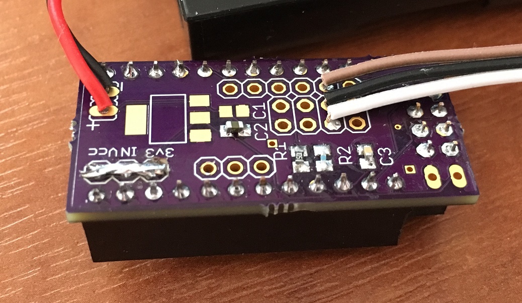
I've just actually got around to soldering mine together today after having the pcb's sitting there for months. I had ordered a load of capacitors and resistors but rather naively didn't realise that there were different sizes for smd components, silly looking back now but just didn't realise. My soldering skills have improved slightly though so had another go and managed to assemble it today. Biggest problem was remembering what smd components were which as the ebay sellers never label them well.
Have you ordered some already?
Col
-
I've just actually got around to soldering mine together today after having the pcb's sitting there for months. I had ordered a load of capacitors and resistors but rather naively didn't realise that there were different sizes for smd components, silly looking back now but just didn't realise. My soldering skills have improved slightly though so had another go and managed to assemble it today. Biggest problem was remembering what smd components were which as the ebay sellers never label them well.
Have you ordered some already?
Col
@chickey said:
Have you ordered some already?
Yes. As it happens, I soldered one together today too. I'm disappointed that the radio board adds to the overall length rather than folding back over the pro mini (a "U" shape, with the radio board floating above the pro mini, would have made the totality more compact). I do like the built-in voltage divider though for measuring higher voltage external batteries. That's useful to have, and it barely adds anything to the cost.
The JModule (presently on order) should turn out to be more compact, so I'm looking forward to that.
In my case, I had purchased a variety pack of SMD resistors and capacitors from Amazon, and everything was nicely labeled. :satisfied: If you end up buying more, I'd recommend it.
-
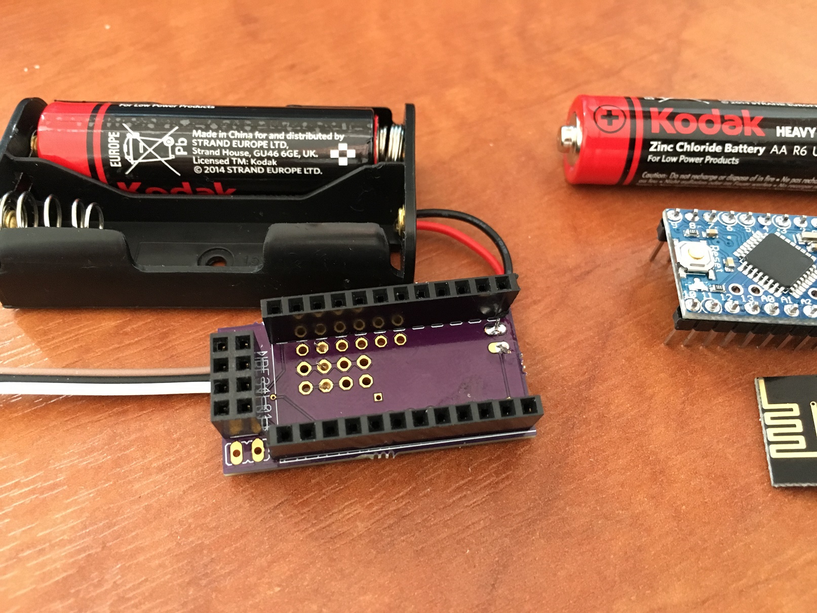
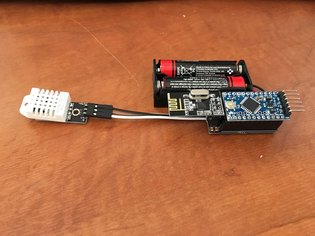
What size SMD did you use for yours? I might see if i can get a variety pack myself from amazon, i'm in the uk so have access to amazon. I think one of the resistors is 470r rather than 470k so the voltage divider didn't work although as i'm feeding it with 3v from two AA i used the internal reference method which worked well. I have to say i thought it ended up being quite long too and then when paired with the sensors you end up with some funny shapes to try and fit in a box :-)
Col
-
@chickey said:
Have you ordered some already?
Yes. As it happens, I soldered one together today too. I'm disappointed that the radio board adds to the overall length rather than folding back over the pro mini (a "U" shape, with the radio board floating above the pro mini, would have made the totality more compact). I do like the built-in voltage divider though for measuring higher voltage external batteries. That's useful to have, and it barely adds anything to the cost.
The JModule (presently on order) should turn out to be more compact, so I'm looking forward to that.
In my case, I had purchased a variety pack of SMD resistors and capacitors from Amazon, and everything was nicely labeled. :satisfied: If you end up buying more, I'd recommend it.
-
What size SMD did you use for yours? I might see if i can get a variety pack myself from amazon, i'm in the uk so have access to amazon. I think one of the resistors is 470r rather than 470k so the voltage divider didn't work although as i'm feeding it with 3v from two AA i used the internal reference method which worked well. I have to say i thought it ended up being quite long too and then when paired with the sensors you end up with some funny shapes to try and fit in a box :-)
Col
-
@NeverDie the reason the radio sticks out is that otherwise the other components would be blocking the radio signal from reaching the antenna.
@mfalkvidd said:
@NeverDie the reason the radio sticks out is that otherwise the other components would be blocking the radio signal from reaching the antenna.
Not sure what you mean. Ssensebender seems to get by that way, doesn't it?
-
@mfalkvidd said:
@NeverDie the reason the radio sticks out is that otherwise the other components would be blocking the radio signal from reaching the antenna.
Not sure what you mean. Ssensebender seems to get by that way, doesn't it?
@NeverDie I've got a few sensebenders and the range isn't great on them. i'm beginning to wonder if its because of the way the Radio is mounted of the PCB.
-
@mfalkvidd said:
@NeverDie the reason the radio sticks out is that otherwise the other components would be blocking the radio signal from reaching the antenna.
Not sure what you mean. Ssensebender seems to get by that way, doesn't it?
@NeverDie said:
Not sure what you mean. Ssensebender seems to get by that way, doesn't it?
The sensebender PCB is blank in the area below where the antenna is.
https://www.openhardware.io/uploads/568d7feb0779a3581858ac2a/394/micro_radio.png
-
@NeverDie said:
Not sure what you mean. Ssensebender seems to get by that way, doesn't it?
The sensebender PCB is blank in the area below where the antenna is.
https://www.openhardware.io/uploads/568d7feb0779a3581858ac2a/394/micro_radio.png
-
If anyone is thinking of using this board Cory produced a PDF which has build instructions for 3.3 and 5v, I've uploaded it so it's easy for people to find.
-
@Sparkman
Thanks! Makes sense. That clears up what you all are referring to.Now you have me wondering: is the JModule experiencing a problem in this regard?
@NeverDie said:
@Sparkman
Thanks! Makes sense. That clears up what you all are referring to.Now you have me wondering: is the JModule experiencing a problem in this regard?
It will definitely have reduced range in that direction, but any range issues can likely be minimized by orienting it differently. Would be interesting to compare the actual range reduction of it compared to the Sensebender.
-
@NeverDie said:
@Sparkman
Thanks! Makes sense. That clears up what you all are referring to.Now you have me wondering: is the JModule experiencing a problem in this regard?
It will definitely have reduced range in that direction, but any range issues can likely be minimized by orienting it differently. Would be interesting to compare the actual range reduction of it compared to the Sensebender.
@Sparkman
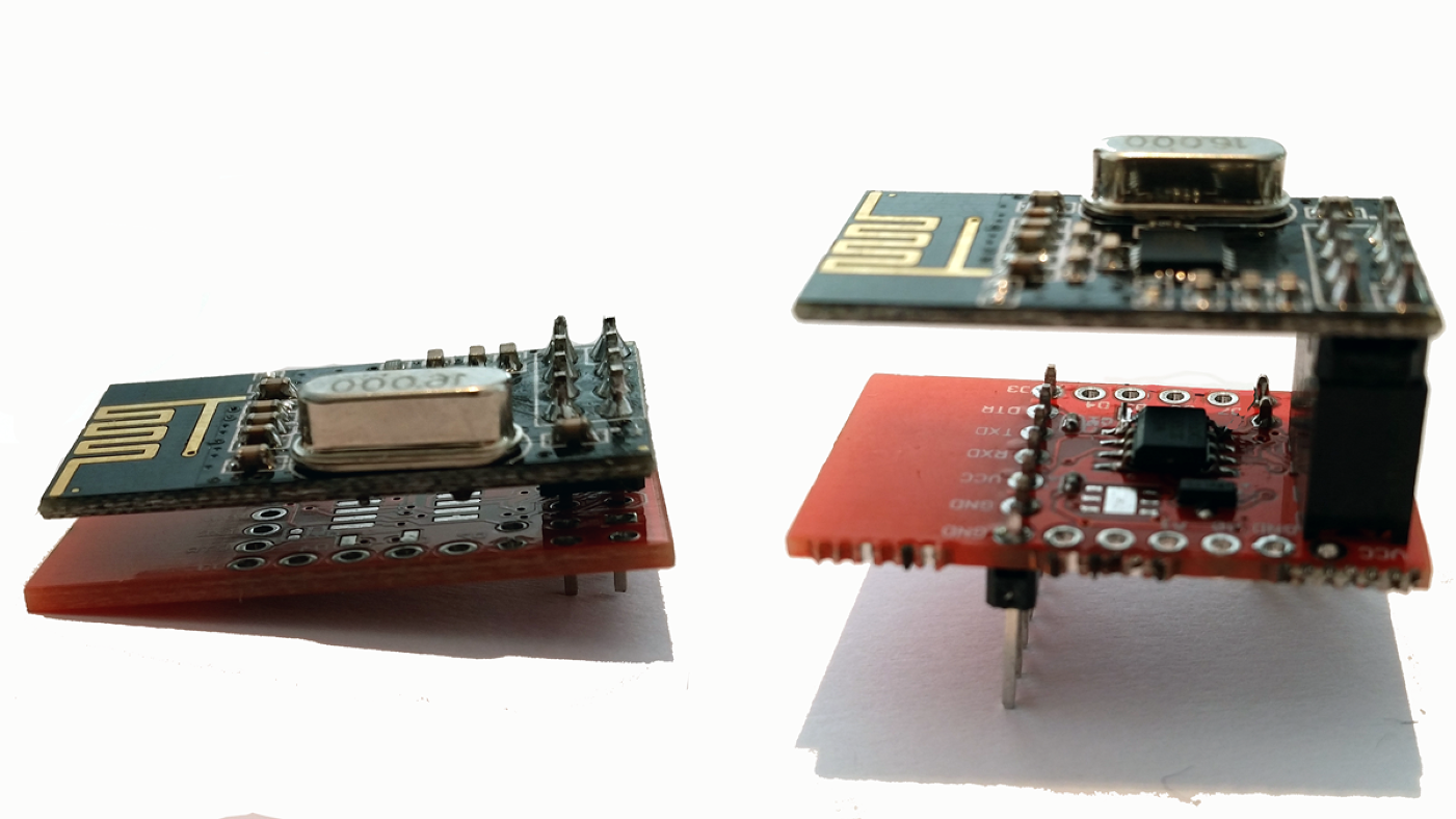
Here's a photo of the one I put together:
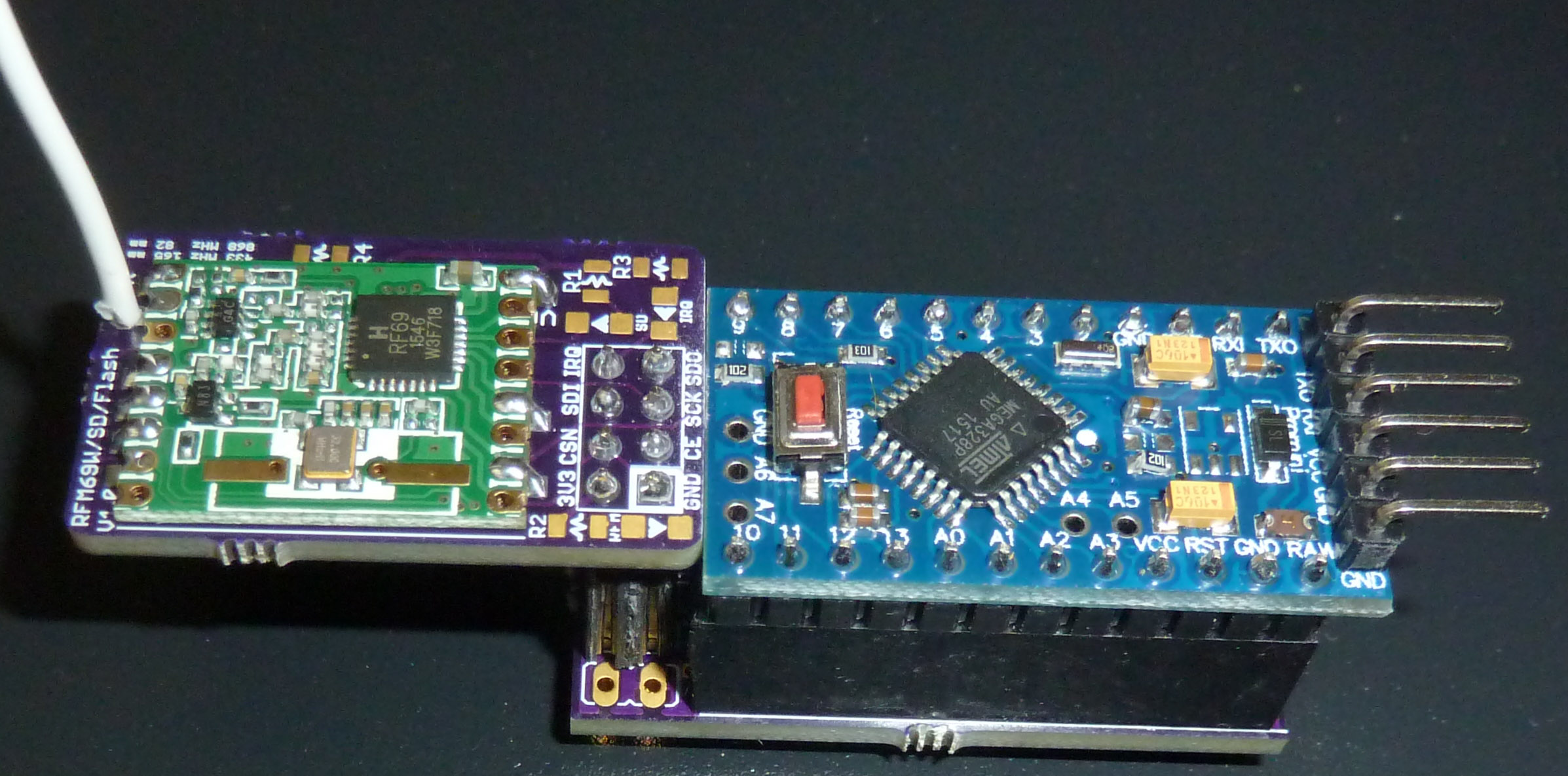
Now you can see why, if it had been bent in a "U", I wasn't extremely concerned about having a blank area underneath. :wink: It would have had a ground plane between the RFM69 and the pro mini. Of course, in that case, I would have soldered the pro mini directly to the adapter board, so that it would be out of the way for the RFM69HW to float above it.
The pro mini's are nice because most of the tricky soldering has already been done for you, and they're nearly the same price as just the atmega328p component just by itself. I'm frankly puzzled as to why more designs don't leverage that obvious fact. True, there is some unsoldering work, which is a bit of a hassle: as you can see, I removed the voltage regulator and the two LEDs so that it doesn't waste any energy when running on two AA's. @chickey You may want to do similar, or else you'll waste energy from backfeeding your pro mini's voltage regulator.
-
@Sparkman
Here's a photo of the one I put together:
Now you can see why, if it had been bent in a "U", I wasn't extremely concerned about having a blank area underneath. :wink: It would have had a ground plane between the RFM69 and the pro mini. Of course, in that case, I would have soldered the pro mini directly to the adapter board, so that it would be out of the way for the RFM69HW to float above it.
The pro mini's are nice because most of the tricky soldering has already been done for you, and they're nearly the same price as just the atmega328p component just by itself. I'm frankly puzzled as to why more designs don't leverage that obvious fact. True, there is some unsoldering work, which is a bit of a hassle: as you can see, I removed the voltage regulator and the two LEDs so that it doesn't waste any energy when running on two AA's. @chickey You may want to do similar, or else you'll waste energy from backfeeding your pro mini's voltage regulator.
Hello! It looks like you're interested in this conversation, but you don't have an account yet.
Getting fed up of having to scroll through the same posts each visit? When you register for an account, you'll always come back to exactly where you were before, and choose to be notified of new replies (either via email, or push notification). You'll also be able to save bookmarks and upvote posts to show your appreciation to other community members.
With your input, this post could be even better 💗
Register Login