Skip to content
  • OpenHardware.io
  • Categories
  • Recent
  • Tags
  • Popular
Skins
  • Light
  • Brite
  • Cerulean
  • Cosmo
  • Flatly
  • Journal
  • Litera
  • Lumen
  • Lux
  • Materia
  • Minty
  • Morph
  • Pulse
  • Sandstone
  • Simplex
  • Sketchy
  • Spacelab
  • United
  • Yeti
  • Zephyr
  • Dark
  • Cyborg
  • Darkly
  • Quartz
  • Slate
  • Solar
  • Superhero
  • Vapor

  • Default (No Skin)
  • No Skin
Collapse
Brand Logo
  1. Home
  2. Troubleshooting
  3. Motion Sensor triggering on its own
  • Getting Started
  • Controller
  • Build
  • Hardware
  • Download/API
  • Forum
  • Store

Motion Sensor triggering on its own

Scheduled Pinned Locked Moved Troubleshooting
39 Posts 19 Posters 24.9k Views 13 Watching
  • Oldest to Newest
  • Newest to Oldest
  • Most Votes
Reply
  • Reply as topic
Log in to reply
This topic has been deleted. Only users with topic management privileges can see it.
  • ahmedadelhosniA ahmedadelhosni

    I was testing the below sensor with 3.3v and it was reporting false status. It worked well with 5v. Although the site claims it works between 3 to 5 volts.
    Maybe power issues

    http://store.fut-electronics.com/products/pir-motion-sensor-module-adjustable-range

    M Offline
    M Offline
    Maciej Kulawik
    wrote on last edited by
    #25

    @ahmedadelhosni All those PIRs are built using the same chip. All all have 3,3v regulator onboard, so they always work with 3,3v. I don't understand why powering directly with 3,2v from battery makes so trouble.
    Maybe this LDO regulator adds some additional stabilisation/filtering on power line, when powered with greater voltage...

    rvendrameR ahmedadelhosniA 2 Replies Last reply
    0
    • M Maciej Kulawik

      @ahmedadelhosni All those PIRs are built using the same chip. All all have 3,3v regulator onboard, so they always work with 3,3v. I don't understand why powering directly with 3,2v from battery makes so trouble.
      Maybe this LDO regulator adds some additional stabilisation/filtering on power line, when powered with greater voltage...

      rvendrameR Offline
      rvendrameR Offline
      rvendrame
      Hero Member
      wrote on last edited by
      #26

      @Maciej-Kulawik It can be that the on-board LDO needs more than 3.3v to activate. It maybe even dropping the voltage from batteries, and doing nothing but disturbing :-) Maybe it worth to remove it when running the circuit with 3V from batteries.

      Home Assistant / Vera Plus UI7
      ESP8266 GW + mySensors 2.3.2
      Alexa / Google Home

      M 1 Reply Last reply
      0
      • rvendrameR rvendrame

        @Maciej-Kulawik It can be that the on-board LDO needs more than 3.3v to activate. It maybe even dropping the voltage from batteries, and doing nothing but disturbing :-) Maybe it worth to remove it when running the circuit with 3V from batteries.

        M Offline
        M Offline
        Maciej Kulawik
        wrote on last edited by
        #27

        @rvendrame But I work only with pirs with ldo removed (and diode).

        rvendrameR 1 Reply Last reply
        0
        • M Maciej Kulawik

          @rvendrame But I work only with pirs with ldo removed (and diode).

          rvendrameR Offline
          rvendrameR Offline
          rvendrame
          Hero Member
          wrote on last edited by
          #28

          @Maciej-Kulawik if so, your PIR looks to need at least 3.3V, so the ~3V from 2xAA is not enough and it is causing instabilities (probably the same as reported by others here).

          Home Assistant / Vera Plus UI7
          ESP8266 GW + mySensors 2.3.2
          Alexa / Google Home

          1 Reply Last reply
          0
          • M Maciej Kulawik

            @ahmedadelhosni All those PIRs are built using the same chip. All all have 3,3v regulator onboard, so they always work with 3,3v. I don't understand why powering directly with 3,2v from battery makes so trouble.
            Maybe this LDO regulator adds some additional stabilisation/filtering on power line, when powered with greater voltage...

            ahmedadelhosniA Offline
            ahmedadelhosniA Offline
            ahmedadelhosni
            wrote on last edited by
            #29

            @Maciej-Kulawik I didnt know that info. Thanks.

            1 Reply Last reply
            0
            • L Offline
              L Offline
              LastSamurai
              Hardware Contributor
              wrote on last edited by
              #30

              Did you guys get them working? I tried to power the pir sensor via the "H" pad directly with 3.3V from a boost converter (via a coin cell). Now I get random readings that I didn't have when using a stable 3.3V source. Any ideas how to solve this?
              I haven't (yet) removed the voltage regulator on board. Perhaps that might help...

              1 Reply Last reply
              0
              • ChakkieC Offline
                ChakkieC Offline
                Chakkie
                wrote on last edited by Chakkie
                #31

                I have the same issue first when I tried to power the PIR with the VCC from the arduino mini pro 3.3V. It seems like the PIR does not work with 3.3V. Now I power the PIR directly from the 9V battery. Problem solved.

                Raspberry Pi 2
                Domoticz
                RFXCOM
                ZWAVE Aeon stick
                Coming soon Arduino mysensors GW

                1 Reply Last reply
                0
                • fifipil909F Offline
                  fifipil909F Offline
                  fifipil909
                  wrote on last edited by
                  #32

                  Hi,

                  False detection is only due to power stability issue.
                  Personnaly i remove the regulator and power the PIR without any boost on the VCC pin. Even below 2v the PIR continue working without any a single issue.

                  Did you try to do a small delay before sleeping with interupt ? See my post a bit upper.

                  For me it solve all my false trigger issue.

                  1 Reply Last reply
                  0
                  • m26872M Offline
                    m26872M Offline
                    m26872
                    Hardware Contributor
                    wrote on last edited by
                    #33

                    I know this thread's about hc-501. But I guess one can apply some of my hc-505 (mini-pir) experiences from here:
                    https://forum.mysensors.org/topic/2715/slim-node-as-a-mini-2aa-battery-pir-motion-sensor

                    1 Reply Last reply
                    0
                    • F Offline
                      F Offline
                      Fabien
                      wrote on last edited by Fabien
                      #34

                      Same problem here every time m node wake-up I have a false trigger. With delay (@fifipil909) it's not better

                      1 Reply Last reply
                      0
                      • L Offline
                        L Offline
                        LastSamurai
                        Hardware Contributor
                        wrote on last edited by
                        #35

                        Mhm I still have strange results from my PIR sensor (doesn't even seem to be the wake up that influences them).
                        I have the pir with diode and voltage regulator removed powered by a boost converter with the low pass filter and a pull down resistor. Using a clean 3.3V worked though, but I really want to use batteries (with sometimes less than 3V). Directly powering the sensor with the 2.x V did not work either.
                        For one of the guys with working sensors: what is your exact setup? None of the tipps I found seem to work. I would really love to get one sensor running. Only idea I still have is to try with another sensor.

                        Here is the code I am currently using:

                        
                        #include <MySensor.h>  
                        #include <SPI.h>
                        
                        unsigned long SLEEP_TIME = 120000; // Sleep time between reports (in milliseconds)
                        #define DIGITAL_INPUT_SENSOR 3   // The digital input you attached your motion sensor.  (Only 2 and 3 generates interrupt!)
                        #define INTERRUPT DIGITAL_INPUT_SENSOR-2 // Usually the interrupt = pin -2 (on uno/nano anyway)
                        #define CHILD_ID 1   // Id of the sensor child
                        
                        #ifdef DEBUG
                        #define DEBUG_SERIAL(x) Serial.begin(x)
                        #define DEBUG_PRINT(x) Serial.print(x)
                        #define DEBUG_PRINTLN(x) Serial.println(x)
                        #else
                        #define DEBUG_SERIAL(x)
                        #define DEBUG_PRINT(x) 
                        #define DEBUG_PRINTLN(x) 
                        #endif
                        
                        MySensor gw;
                        // Initialize motion message
                        MyMessage msg(CHILD_ID, V_TRIPPED);
                        
                        void setup()  
                        {  
                        
                          DEBUG_SERIAL(9600);    // <<<<<<<<<<<<<<<<<<<<<<<<<< Note BAUD_RATE in MySensors.h
                          DEBUG_PRINTLN("Serial started");
                        
                          gw.begin();
                        
                          // Send the sketch version information to the gateway and Controller
                          gw.sendSketchInfo("Motion Sensor Test", "24052016");
                        
                          pinMode(DIGITAL_INPUT_SENSOR, INPUT);      // sets the motion sensor digital pin as input
                          // Register all sensors to gw (they will be created as child devices)
                          gw.present(CHILD_ID, S_MOTION);
                          
                        }
                        
                        void loop()     
                        {     
                          // Read digital motion value
                          boolean tripped = digitalRead(DIGITAL_INPUT_SENSOR) == HIGH; 
                          DEBUG_PRINT("Got tripped: ");
                          DEBUG_PRINTLN(tripped);
                                
                          gw.send(msg.set(tripped?"1":"0"));  // Send tripped value to gw 
                         
                          DEBUG_PRINTLN("Sleeping till next interrupt");
                        
                          // Sleep until interrupt comes in on motion sensor. Send update every two minute. 
                          //gw.sleep(INTERRUPT,CHANGE, SLEEP_TIME);
                          // Sleep until interrupt comes in on motion sensor. Won't wake up otherwise
                          gw.sleep(500);
                          gw.sleep(INTERRUPT, CHANGE, 0);
                          //gw.sleep(INTERRUPT, RISING, 0);
                        }
                        
                        
                        1 Reply Last reply
                        0
                        • L Offline
                          L Offline
                          LastSamurai
                          Hardware Contributor
                          wrote on last edited by
                          #36

                          Does anyone have an idea how to get the pir sensor running with a coin cell? Or perhaps if that doesn't work with 2 aa's? See my post above

                          1 Reply Last reply
                          0
                          • L Offline
                            L Offline
                            Luca Fabbriani
                            wrote on last edited by
                            #37

                            Sorry for necroposting on my first forum post but I have the exact same issue at the moment. I power PIR sensors from the same 3.3V switching regulator that powers an esp12 module. I took off the anti-inversion diode and the linear regulator, added a 470uF and 100nF capacitor on the sensor supply input. This has been done to two sensors, one is working flawlessly the other one has a false trigger once every half an hour.
                            Adding HF and LF bypass capacitors with some improvement told me that was a supply instability issue but it's not solving the problem completely. My suspect is that the polarity inversion diode that I took off had a role in the play improving the supply voltage stability.....I'll try to put back the diode and I'll let you know.

                            cheers
                            Luca

                            1 Reply Last reply
                            1
                            • N Offline
                              N Offline
                              Natezimmer
                              wrote on last edited by
                              #38

                              This is an issue i've been fighting for awhile as well. In industry, i've encountered PIR modules / old sensors can be susceptible to high freq interference. E.g. I have WiFi on my PI.

                              1. Ensure the PIR is a 6in+ physical distance from your dev board / any radios. This helps.

                              2. Ensure no high freq noise can couple on any of the 3 wires connected to the PIR

                              0_1560114349879_c4ca7289-112c-4d3e-88c8-9aeea62ec2b9-image.png

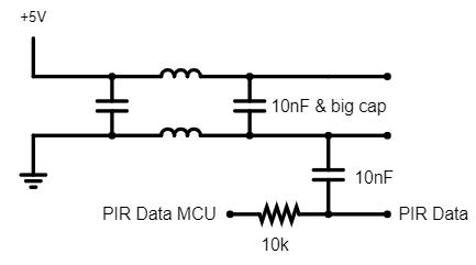
                              I did #2 via a PI filter. Inductors + a cap. Ideally i'd have caps at both ends of high and low values for both frequency contents. The signal line itself can couple noise so ideally a ferrite bead + resistor to snub any type of noise. I've had to employ similar strategies with other sensors to deal w/ interference issues.

                              1 Reply Last reply
                              0
                              • W Offline
                                W Offline
                                Wikibear
                                wrote on last edited by
                                #39

                                Have this same issue and it makes me crazy... I use a step up converter DCDC 1.8V up to 3.3 input and output 3.3V. If solder from DCDC Out via 220uF direct soldered after stabilizer of HC501 direct on pcb and sometimes it will detect motion where no motion happens. I use two AA accu and i know that they have together 2,4V. Less voltage less current. But i try also with normal AA 3V then i have this issue not so often. But i have. It will much more if the voltage will more less.

                                1 Reply Last reply
                                0
                                Reply
                                • Reply as topic
                                Log in to reply
                                • Oldest to Newest
                                • Newest to Oldest
                                • Most Votes


                                18

                                Online

                                11.7k

                                Users

                                11.2k

                                Topics

                                113.0k

                                Posts


                                Copyright 2019 TBD   |   Forum Guidelines   |   Privacy Policy   |   Terms of Service
                                • Login

                                • Don't have an account? Register

                                • Login or register to search.
                                • First post
                                  Last post
                                0
                                • OpenHardware.io
                                • Categories
                                • Recent
                                • Tags
                                • Popular