How To - Doorbell Automation Hack
-
I am new to home automation but curious if this same setup would work by having the arduino centrally located with the transformer in a closet and use the extra connections on the existing 4 conductor wire from the transformer to connect the new relay installed in the chime?
All this saves is some extra space and having to run 5V to the chime but one could use a larger arduino for additional automation projects rather than dedicated to just the chime.
Very nice tutorial- very easy to follow. Thanks
-
Hey @mike0913 ,
You can check out what I did with my Doorbell hack here (http://forum.mysensors.org/topic/2293/how-to-2-door-chime-automation-hack-thanks-petewill), it may help with your situation. Basically, I used the 16VAC input from the doorbell to power my Arduino, relays, and actual doorbell chime itself. Due to confined space, I had to mount mine in an external box below the existing door chime.
-
@petewill, thanks for the reply and sorry it took me so long. I have decided to keep it to a small project starting with the remote on off, then moving to a trigger to my camera. I plan on breaking the doorbell down once the wife is out of the house for a day, lol. Thanks again.
-
Hi Everyone,
I put together this quick how to video for hacking your doorbell to work with MySensors. It's pretty basic and the code is based on the Relay Actuator sketch. It has two main features: controlling if the doorbell rings with an on/off switch and sending a triggered state whenever it's pressed. The silence feature can be useful if a child (or you) is taking a nap. The triggered state can be used for many different things like starting a security camera, sending an alert or text message, playing custom sounds via Sonos or other device, etc. Another note, the doorbell will still function even if your home automation the controller is down for some reason.
Here are the additional details:
https://youtu.be/nMIcalwpstc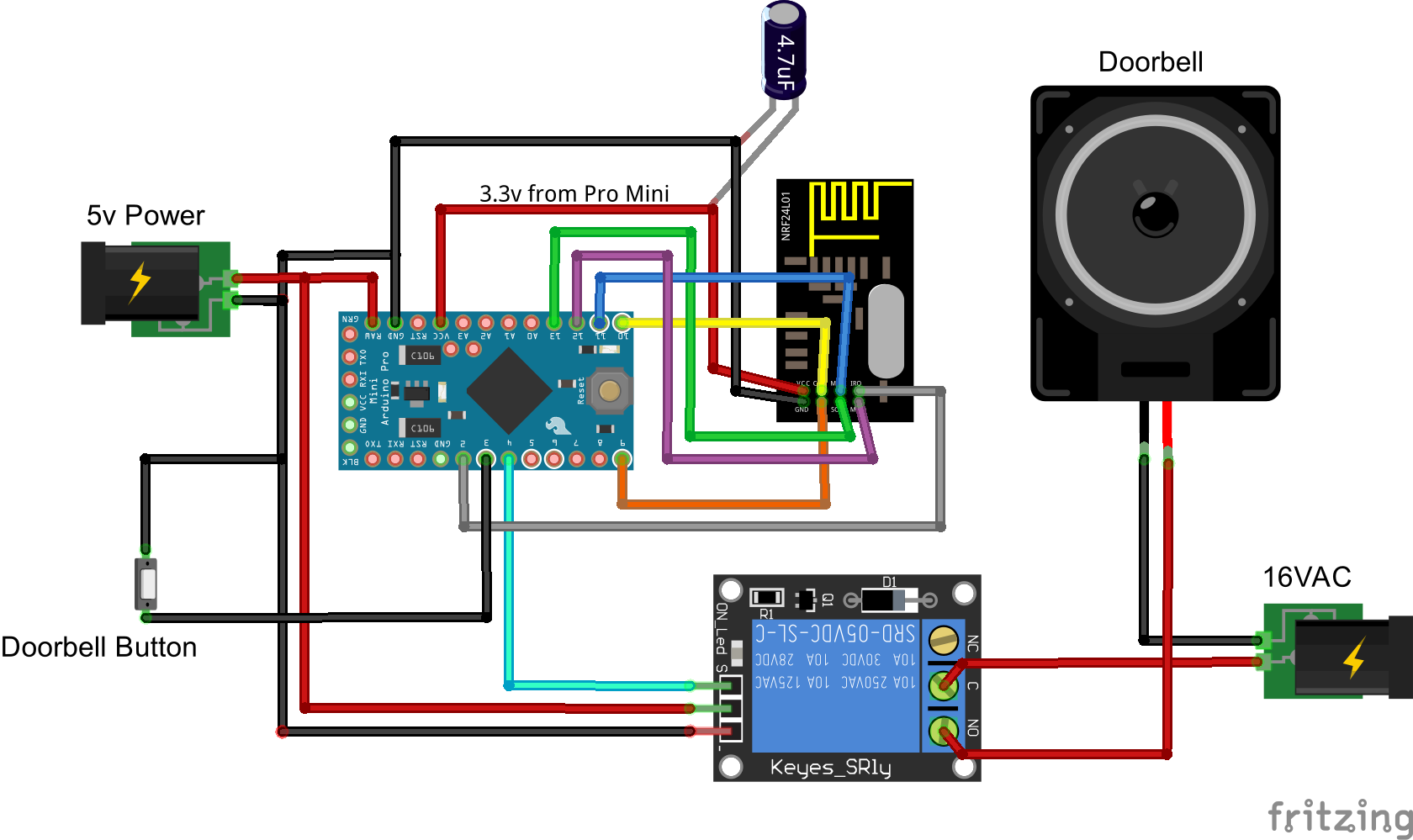
/* * The MySensors Arduino library handles the wireless radio link and protocol * between your home built sensors/actuators and HA controller of choice. * The sensors forms a self healing radio network with optional repeaters. Each * repeater and gateway builds a routing tables in EEPROM which keeps track of the * network topology allowing messages to be routed to nodes. * * Created by Henrik Ekblad <henrik.ekblad@mysensors.org> * Copyright (C) 2013-2015 Sensnology AB * Full contributor list: https://github.com/mysensors/Arduino/graphs/contributors * * Documentation: http://www.mysensors.org * Support Forum: http://forum.mysensors.org * * This program is free software; you can redistribute it and/or * modify it under the terms of the GNU General Public License * version 2 as published by the Free Software Foundation. * ******************************* * * REVISION HISTORY * Version 1.0 - PeteWill * * DESCRIPTION * This sketch is used to control a doorbell ring with a relay as well as send an * alert when the buttons is pressed. Connect the button to ground and digital * pin 3. The relay controlling the doorbell is conntected to pin 4. * * Watch the How To video here: https://youtu.be/nMIcalwpstc */ #include <MySensor.h> #include <SPI.h> #include <Bounce2.h> #define NODE_ID 16 // or set to AUTO if you want gw to assign a NODE_ID for you. #define DOORBELL_PIN 3 // Arduino Digital I/O pin number for the doorbell button #define RELAY_PIN 4 // Arduino Digital I/O pin number for the relay #define DOORBELL_CHILD_ID 0 //ID of the doorbell #define SWITCH_CHILD_ID 1 // Id of the switch that will control doorbell sound #define RELAY_ON 1 #define RELAY_OFF 0 Bounce debouncer = Bounce(); MySensor gw; MyMessage switchMsg(SWITCH_CHILD_ID, V_LIGHT); MyMessage doorbellMsg(DOORBELL_CHILD_ID, V_TRIPPED); unsigned int doorbellDelay = 1000; // interval at which to keep the doorbell button sensor triggered (milliseconds). This is used to stop people (kids) from pressing it too often unsigned int ringTime = 700; //How long the doorbell relay is on (in milliseconds) unsigned long doorbellMillis; //Used to keep track of the last doorbell button press unsigned long doorbellTimer; //Used to keep track of doorbell ring time byte doorbellPreviousVal; //Used to keep track of doorbell button pressed state boolean ringDoorbell; //Used to initiate the ring doorbell if statement boolean doorbellSound; //Used to keep track if the doorbell should sound or be silent. Value recieved from doorbell on/off switch boolean doorbellOff = true; //Used to keep track of doorbell ring state void setup() { gw.begin(incomingMessage, NODE_ID); // Send the sketch version information to the gateway and Controller gw.sendSketchInfo("Doorbell Monitor", "1.0"); // Setup the button and activate internal pull-up pinMode(DOORBELL_PIN, INPUT_PULLUP); // After setting up the button, setup debouncer debouncer.attach(DOORBELL_PIN); debouncer.interval(5); // Register all sensors to gw (they will be created as child devices) gw.present(SWITCH_CHILD_ID, S_LIGHT); gw.present(DOORBELL_CHILD_ID, S_MOTION); // Make sure relays are off when starting up digitalWrite(RELAY_PIN, RELAY_OFF); // Then set relay pins in output mode pinMode(RELAY_PIN, OUTPUT); // Set doorbellSound to last known state (using eeprom storage) doorbellSound = gw.loadState(SWITCH_CHILD_ID); } void loop() { gw.process(); unsigned long currentMillis = millis(); //Check to see if doorbell button was pushed. if (currentMillis - doorbellMillis > doorbellDelay) //used to stop doorbell from being pressed too frequently { debouncer.update(); // Read doorbell button value byte doorbellDetect = !debouncer.read();//read, then reverse the value so it will send correct trigger state to controller if (doorbellDetect != doorbellPreviousVal) { //Serial.print("doorbellDetect Value: "); //Serial.println(doorbellDetect); gw.send(doorbellMsg.set(doorbellDetect)); if (doorbellDetect == 1) { ringDoorbell = true; doorbellTimer = currentMillis; } doorbellMillis = currentMillis; doorbellPreviousVal = doorbellDetect; } } if (ringDoorbell) { if (doorbellSound) { if (doorbellOff) { digitalWrite(RELAY_PIN, RELAY_ON); //Serial.println("Doorbell sounded."); doorbellOff = false; } else { if (currentMillis - doorbellTimer > ringTime) { ringDoorbell = false; digitalWrite(RELAY_PIN, RELAY_OFF); //Serial.println("Doorbell off."); doorbellOff = true; } } } } } void incomingMessage(const MyMessage & message) { // We only expect one type of message from controller. But we better check anyway. if (message.isAck()) { Serial.println("This is an ack from gateway"); } if (message.type == V_LIGHT) { // Change relay state doorbellSound = message.getBool(); // Store state in eeprom gw.saveState(SWITCH_CHILD_ID, doorbellSound); // Write some debug info Serial.print("Incoming change for sensor:"); Serial.print(message.sensor); Serial.print(", New status: "); Serial.println(message.getBool()); } }Thanks for the code! For some reason it is not functioning on my arduino pro, the relay doesnt do anything when I push the button on pin 3, I do see within the Vera that the button is being pushed I have no clue what is going wrong..
This is the output from the serial monitor:
send: 16-16-0-0 s=255,c=3,t=15,pt=2,l=2,sg=0,st=ok:0
send: 16-16-0-0 s=255,c=0,t=17,pt=0,l=5,sg=0,st=ok:1.5.3
send: 16-16-0-0 s=255,c=3,t=6,pt=1,l=1,sg=0,st=ok:0
sensor started, id=16, parent=0, distance=1
send: 16-16-0-0 s=255,c=3,t=11,pt=0,l=16,sg=0,st=ok:Doorbell Monitor
send: 16-16-0-0 s=255,c=3,t=12,pt=0,l=3,sg=0,st=ok:1.0
send: 16-16-0-0 s=1,c=0,t=3,pt=0,l=0,sg=0,st=ok:
send: 16-16-0-0 s=0,c=0,t=1,pt=0,l=0,sg=0,st=ok:
Pushing button
send: 16-16-0-0 s=0,c=1,t=16,pt=1,l=1,sg=0,st=ok:1
send: 16-16-0-0 s=0,c=1,t=16,pt=1,l=1,sg=0,st=ok:0
Pushing button
send: 16-16-0-0 s=0,c=1,t=16,pt=1,l=1,sg=0,st=ok:1
send: 16-16-0-0 s=0,c=1,t=16,pt=1,l=1,sg=0,st=ok:0Anybody that can help me out?
Thanks!
Kind regards,
Richard
-
Thanks for the code! For some reason it is not functioning on my arduino pro, the relay doesnt do anything when I push the button on pin 3, I do see within the Vera that the button is being pushed I have no clue what is going wrong..
This is the output from the serial monitor:
send: 16-16-0-0 s=255,c=3,t=15,pt=2,l=2,sg=0,st=ok:0
send: 16-16-0-0 s=255,c=0,t=17,pt=0,l=5,sg=0,st=ok:1.5.3
send: 16-16-0-0 s=255,c=3,t=6,pt=1,l=1,sg=0,st=ok:0
sensor started, id=16, parent=0, distance=1
send: 16-16-0-0 s=255,c=3,t=11,pt=0,l=16,sg=0,st=ok:Doorbell Monitor
send: 16-16-0-0 s=255,c=3,t=12,pt=0,l=3,sg=0,st=ok:1.0
send: 16-16-0-0 s=1,c=0,t=3,pt=0,l=0,sg=0,st=ok:
send: 16-16-0-0 s=0,c=0,t=1,pt=0,l=0,sg=0,st=ok:
Pushing button
send: 16-16-0-0 s=0,c=1,t=16,pt=1,l=1,sg=0,st=ok:1
send: 16-16-0-0 s=0,c=1,t=16,pt=1,l=1,sg=0,st=ok:0
Pushing button
send: 16-16-0-0 s=0,c=1,t=16,pt=1,l=1,sg=0,st=ok:1
send: 16-16-0-0 s=0,c=1,t=16,pt=1,l=1,sg=0,st=ok:0Anybody that can help me out?
Thanks!
Kind regards,
Richard
Never mind, I didnt know I had to enable both switches within the arduino interface... ahum..
Thanks anyhoe!
Kind regards
Richard
-
Excellent hack, works like a charm! I added two extra activations for my doorbell so it rings two times short and one longer time... Is there a way to create a variable in the Vera options so you can change the number of time the relay activates? Now I added them in the code but that is not really handy when the thing is build in and such... :)
Thanks!
@riochicken said:
Is there a way to create a variable in the Vera options so you can change the number of time the relay activates?
Yeah, that should be possible. Have a look at the Irrigation Controller code. That has some examples of getting variables from the controller.
-
I had my doorbell working fine on Vera for months, but now I'm switching over to Domoticz. I used the updated domoticz version of the code above (by drock1985) but it's still not working right. My only changes were the pin assignments to match my wiring and setting the repeater to true since it's powered.
My domoticz is version v3.4834. Mysensors ethernet gateway is working fine. When I powered up the doorbell, I got an unknown node with sketch "unknown" show up under mysensors. It has 2 children - a repeater with childID 255, and an unknown with childID 0 and a V_Tripped value.
Any idea what I need to do to make it work?
Try this code and see if it works.
/* * The MySensors Arduino library handles the wireless radio link and protocol * between your home built sensors/actuators and HA controller of choice. * The sensors forms a self healing radio network with optional repeaters. Each * repeater and gateway builds a routing tables in EEPROM which keeps track of the * network topology allowing messages to be routed to nodes. * * Created by Henrik Ekblad <henrik.ekblad@mysensors.org> * Copyright (C) 2013-2015 Sensnology AB * Full contributor list: https://github.com/mysensors/Arduino/graphs/contributors * * Documentation: http://www.mysensors.org * Support Forum: http://forum.mysensors.org * * This program is free software; you can redistribute it and/or * modify it under the terms of the GNU General Public License * version 2 as published by the Free Software Foundation. * ******************************* * * REVISION HISTORY * Version 2.1 - Derrick Rockwell (Drock1985) * - Complete Re-write of code to provide better flow/structure. * Version 2.0 - ResentedPoet * * Based on original concept/code by @petewill for 1 Door bell chime. See original thread * http://forum.mysensors.org/topic/2064/how-to-doorbell-automation-hack * This sketch is used to control a front and back doorbell ring with relays as well as send an * alert when the buttons are pressed. For front door, Connect the button to ground and digital * pin 3. The relay controlling the doorbell is conntected to pin 4. For rear door bell * connect second button to ground and digital pin 5. The relay controlling that pin goes * to pin 6. */ #include <MySensor.h> #include <SPI.h> #include <Bounce2.h> #define NODE_ID 2 // or set to AUTO if you want gw to assign a NODE_ID for you. #define FRONT_DOOR_BUTTON 3 // Arduino Digital I/O pin number for the front doorbell button #define FRONT_CHIME_RELAY 4 // Aduino Digital I/O pin number for the front door chime relay #define CHILD_ID_0 0 // Child ID for the front doorbell sensor #define BACK_DOOR_BUTTON 5 // Arduino Digital I/O pin number for the back doorbell button #define BACK_CHIME_RELAY 6 // Aduino Digital I/O pin number for the back door chime relay #define CHILD_ID_1 1 // Child ID for the back doorbell sensor #define CHILD_ID_2 2 // Child ID for the mute option #define CHIME_MUTE_STATE // Used to hold value of door chime mute funtion. #define CHIME_OFF 0 // Variable to define ring the chime #define CHIME_ON 1 #define FRONT_CHIME_RELAY_ON LOW // Variable for front chime. Reverse low/high if relay pin set different #define FRONT_CHIME_RELAY_OFF HIGH // Variable for front chime. Reverse low/high if relay pin set different #define BACK_CHIME_RELAY_ON LOW // Variable for front chime. Reverse low/high if relay pin set different #define BACK_CHIME_RELAY_OFF HIGH // Variable for front chime. Reverse low/high if relay pin set different Bounce debouncerF = Bounce(); Bounce debouncerB = Bounce(); boolean CHIME_MUTE = 1; MySensor gw; MyMessage msg(CHILD_ID_2, CHIME_MUTE); MyMessage frontDoorbell(CHILD_ID_0, V_TRIPPED); MyMessage backDoorbell(CHILD_ID_1, V_TRIPPED); MyMessage chimeMute(CHILD_ID_2, V_STATUS); int pestTimeout = 4000; // Delay between registered button presses. Stops button mashers ;) Set to whatever delay you want. unsigned long previousMillis=0; // Tracks time since last door chime button press void setup() { gw.begin(incomingMessage, NODE_ID); // Send the sketch version information to the gateway and Controller gw.sendSketchInfo("2 Door bell/chime Monitor", "2.1"); // Setup the button and activate internal pull-up pinMode(FRONT_DOOR_BUTTON, INPUT); pinMode(BACK_DOOR_BUTTON, INPUT); digitalWrite(FRONT_DOOR_BUTTON, HIGH); digitalWrite(BACK_DOOR_BUTTON, HIGH); // After setting up the button, setup debouncer debouncerF.attach(FRONT_DOOR_BUTTON); debouncerB.attach(BACK_DOOR_BUTTON); debouncerF.interval(5); debouncerB.interval(5); // Register all sensors to gw (they will be created as child devices) gw.present(CHILD_ID_0, S_MOTION); gw.present(CHILD_ID_1, S_MOTION); gw.present(CHILD_ID_2, S_LIGHT); gw.send(msg.set(CHILD_ID_2, CHIME_MUTE)); // Make sure relays are off when starting up digitalWrite(FRONT_CHIME_RELAY, FRONT_CHIME_RELAY_OFF); digitalWrite(BACK_CHIME_RELAY, BACK_CHIME_RELAY_OFF); // Then set relay pins in output mode pinMode(FRONT_CHIME_RELAY, OUTPUT); pinMode(BACK_CHIME_RELAY, OUTPUT); } void loop() { gw.process(); unsigned long currentMillis = millis(); debouncerF.update(); debouncerB.update(); int valueF = debouncerF.read(); int valueB = debouncerB.read(); //Front Doorbell if ( ((unsigned long)(currentMillis - previousMillis) >= pestTimeout) && valueF != HIGH && CHIME_MUTE == 1) { digitalWrite(FRONT_CHIME_RELAY, FRONT_CHIME_RELAY_ON); gw.send(frontDoorbell.set(1)); gw.wait(50); digitalWrite(FRONT_CHIME_RELAY, FRONT_CHIME_RELAY_OFF); gw.send(frontDoorbell.set(0)); previousMillis = currentMillis; } if ( ((unsigned long)(currentMillis - previousMillis) >= pestTimeout) && valueF != HIGH && CHIME_MUTE == 0) { gw.send(frontDoorbell.set(1)); gw.wait(50);; gw.send(frontDoorbell.set(0)); previousMillis = currentMillis; } //Back Doorbell if ( ((unsigned long)(currentMillis - previousMillis) >= pestTimeout) && valueB != HIGH && CHIME_MUTE == 1) { digitalWrite(BACK_CHIME_RELAY, BACK_CHIME_RELAY_ON); gw.send(backDoorbell.set(1)); gw.wait(450); digitalWrite(BACK_CHIME_RELAY, BACK_CHIME_RELAY_OFF); gw.send(backDoorbell.set(0)); previousMillis = currentMillis; } if ( ((unsigned long)(currentMillis - previousMillis) >= pestTimeout) && valueB != HIGH && CHIME_MUTE == 0) { gw.send(backDoorbell.set(1)); gw.wait(50); gw.send(backDoorbell.set(0)); previousMillis = currentMillis; } } void incomingMessage(const MyMessage &message) { // We only expect one type of message from controller. But we better check anyway. if (message.isAck()) { Serial.println("This is an ack from gateway"); } if (message.type == V_STATUS) { // Change relay state CHIME_MUTE = message.getBool(); gw.send(msg.set(CHILD_ID_2, CHIME_MUTE?CHIME_ON:CHIME_OFF)); // Store state in eeprom gw.saveState(CHILD_ID_2, CHIME_MUTE); // Write some debug info Serial.print("Incoming change for sensor:"); Serial.print(message.sensor); Serial.print(", New status: "); Serial.println(message.getBool()); } } -
Tried that sketch (with just changing pin assignments and flipping the relay high/low settings). As soon as I powered it up, the relay started clicking every 4 seconds and it never appeared in Domoticz. I think it's because after the pin is set to input, there's " digitalWrite(FRONT_DOOR_BUTTON, HIGH);" command that's like someone holding the button down.
Went back to the original sketch I used. I changed from an auto NODE_ID to a fixed setting in the defines and re-uploaded it. The device appeared in Domoticz correctly! I've got a "doorbell sketch 1.0" with 3 devices - repeater, the doorbell button as a S_Motion, and the doorbell on/off as a S_Lights.
However, it still doesn't work. My wiring is shown above and it worked great under Vera. Now, I cannot get the doorbell to actually chime. Nor does the outdoor button do anything. I've verified the wiring, but shorting the A0 pin to the ground input doesn't do anything like it should. However, there's ANOTHER ground next to the A0 (under the wireless card), and if I short the A0 to that ground pin, the switch shows on in Domoticz. I can change the wiring since for some reason which ground I use is making a difference.
No matter what, still no relay action though. I tried turning the doorbell on/off switch both ways and it made no difference. In either setting, shorting the two pins turns the switch in Domoticz on.
I was comparing the two sketches (the one I'm using, and the dual-bell one). The single bell sketch sets the button pin with pinmode(Doorbell_pin, input_pullup) where the dual uses input without the pullup. Which should be right?
-
Tried that sketch (with just changing pin assignments and flipping the relay high/low settings). As soon as I powered it up, the relay started clicking every 4 seconds and it never appeared in Domoticz. I think it's because after the pin is set to input, there's " digitalWrite(FRONT_DOOR_BUTTON, HIGH);" command that's like someone holding the button down.
Went back to the original sketch I used. I changed from an auto NODE_ID to a fixed setting in the defines and re-uploaded it. The device appeared in Domoticz correctly! I've got a "doorbell sketch 1.0" with 3 devices - repeater, the doorbell button as a S_Motion, and the doorbell on/off as a S_Lights.
However, it still doesn't work. My wiring is shown above and it worked great under Vera. Now, I cannot get the doorbell to actually chime. Nor does the outdoor button do anything. I've verified the wiring, but shorting the A0 pin to the ground input doesn't do anything like it should. However, there's ANOTHER ground next to the A0 (under the wireless card), and if I short the A0 to that ground pin, the switch shows on in Domoticz. I can change the wiring since for some reason which ground I use is making a difference.
No matter what, still no relay action though. I tried turning the doorbell on/off switch both ways and it made no difference. In either setting, shorting the two pins turns the switch in Domoticz on.
I was comparing the two sketches (the one I'm using, and the dual-bell one). The single bell sketch sets the button pin with pinmode(Doorbell_pin, input_pullup) where the dual uses input without the pullup. Which should be right?
The sketch I use doesn't use internal pull ups; external only.
As for the relay clicking, could be either the jumper on the relay, or not enough current to power it properly.
Not sure why you are having issues with either of the scripts. What type of gateway do you use?
-
It's an ethernet gateway.
I don't think it's really a Mysensors issue though as I think about it - the doorbell should ring when you press the button whether you have the gateway running or not. And I'm not even getting that. In fact, I AM getting the signal to the gateway, but it's not activating the relay.
Is it possible that the doorbell on/off switch isn't working right in the code? I never used that before. I think I'll try tomorrow (kids in bed now, so can't really play around with a doorbell!) removing that switch for now and have it always set to on.
I looked through comparing the sketch I'm using now (the one drock1985 made that's for domoticz) and the original. The only change is moving the gw.send command and changing it slightly. But again, that shouldn't impact the bell physically working. So there's something else going on.
Is there a way to check if the code uploaded to the arduino correctly? I'm using the rboard and a FTDI to upload. I'm wondering if something isn't going weird there and it's not uploading correctly and that's why I'm getting different issues every time I try something...
-
Not really. You could try uploading at a slower speed. Slower speed over serial usually equals less chance of missed data.
Have you tried running this connected to your PC and viewing the data from serial console/window? Copy/paste the output from the serial monitor so we can see what's going on.
-
I have installed the doorbell sketch on my testboard. This just to see how it should be working. First sensor with a relay for me basically :)
But I have a question. I have use the sketch, I have two devices coming up in Domiticz, a security sensor and a light switch. But basically I don't get the function of these buttons?
I think the security sensor responds on the doorbell press?Also I think the other button is to activate the physical doorbell which could switch the relay? But I would expect that the security switch button in Domoticz could also activate the relay remotely, but this is not the case? Because, I don't see an option to switch the relay remotely in Domoticz?
So it is working; but any help is appreciated if somebody could explain the functionallity for me and if this is the expected behavior :)
I know when I was playing with Domoticz the Doorbell sketch would show up as a security light and a light for me. The security light I changed to a motion sensor in Domoticz (click edit on your dashboard/switches tab). After that when I pressed the doorbell button, the motion sensor would switch on to show the button was pressed, then immediately back off. Although for it to turn off automatically, I may have had to tell domoticz to do that after xx seconds, can't remember for sure now.
And yes you are correct, the second switch is a 'mute' for the doorbell. If off, the doorbell won't sound (switch the relay).
-
Hi guys,
I'm nearly there, but need a little help if anyone can!
For my setup I've got a diode bridge followed immediately by a buck converter, so the doorbell's 18v AC comes down to 8v DC. My plan was to run the doorbell AND the arduino off this same supply, but I'm guessing now that it may not be possible. The reason for this was down to there only being 2 wires to the doorbell. The doorbell works fine off 8v DC and so does the arduino. The issue however is when i both power the arduino and the doorbell at the same time of the same supply. The relay opens and then the arduino resets. No chime.
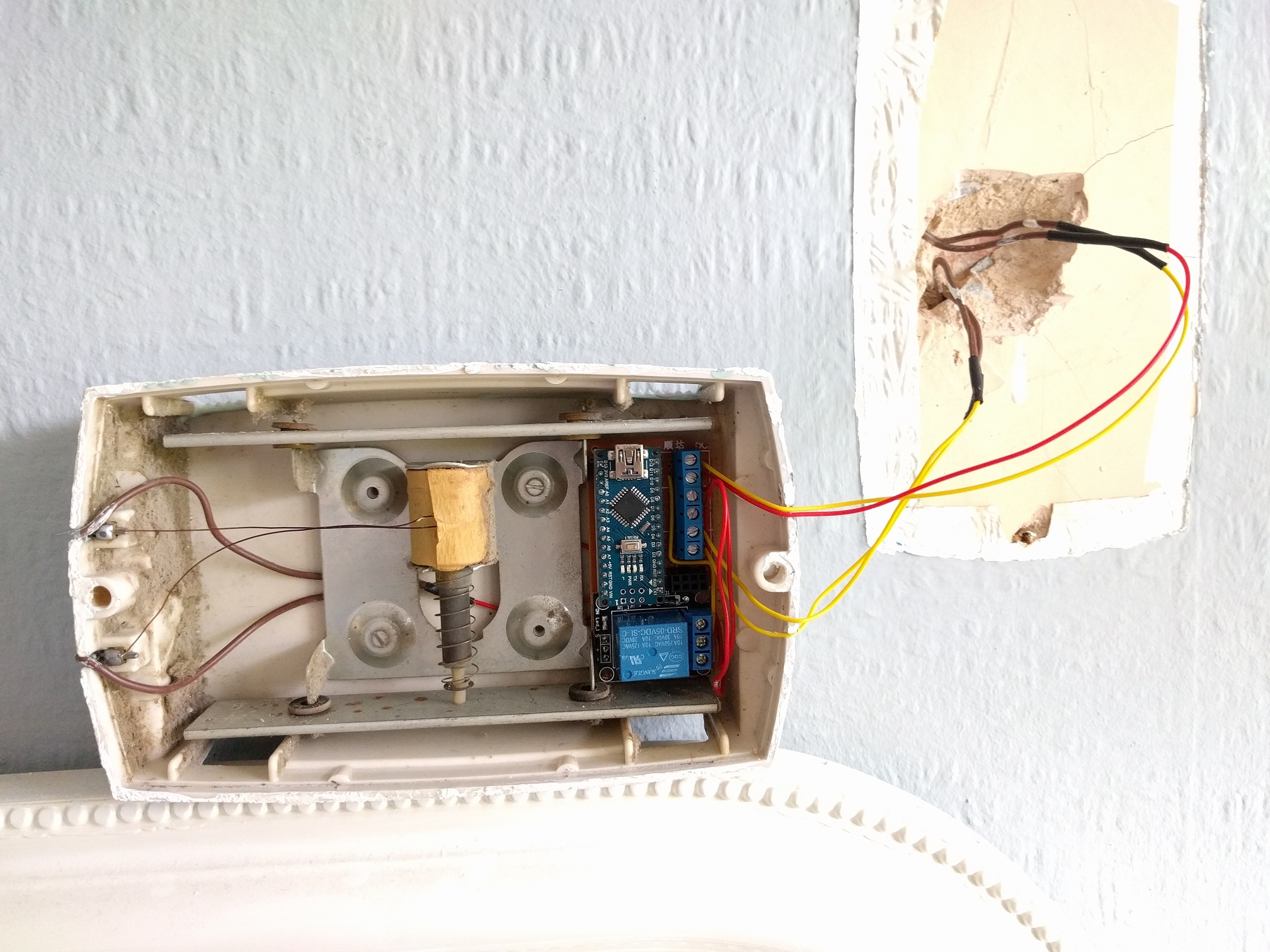
What should I do? Wiring layout is exactly the same as above but the 8v DC loops through the relay to the doorbell as well as going to VIN/GND on the Arduino Nano.
I can't have the arduino at the power supply end as I need the doorbell button connections, so I'm hoping someone might have some ideas around splitting out the power supplies at the doorbell end? Or smoothing it or something like that.
Power is red/yellow from the wall. Doorbell button is yellow/yellow from the wall. brown/brown is soldered/heat shrunk to red/red within the housing. NRF is on headers, so it's lifted out in this photo.
Thanks,
Patrick
-
Or can i just get away with a better power supply for the both? Essentially I've got a pulse-detecting mysensors node, a doorbell node and a doorbell itself running off a cheap-ass ebay chinese full-bridge rectifier and step-down converter (120v AC > 8v DC). The doorbell takes 8v DC so I'm using that as the common voltage.
-
Hi guys,
I'm nearly there, but need a little help if anyone can!
For my setup I've got a diode bridge followed immediately by a buck converter, so the doorbell's 18v AC comes down to 8v DC. My plan was to run the doorbell AND the arduino off this same supply, but I'm guessing now that it may not be possible. The reason for this was down to there only being 2 wires to the doorbell. The doorbell works fine off 8v DC and so does the arduino. The issue however is when i both power the arduino and the doorbell at the same time of the same supply. The relay opens and then the arduino resets. No chime.
What should I do? Wiring layout is exactly the same as above but the 8v DC loops through the relay to the doorbell as well as going to VIN/GND on the Arduino Nano.
I can't have the arduino at the power supply end as I need the doorbell button connections, so I'm hoping someone might have some ideas around splitting out the power supplies at the doorbell end? Or smoothing it or something like that.
Power is red/yellow from the wall. Doorbell button is yellow/yellow from the wall. brown/brown is soldered/heat shrunk to red/red within the housing. NRF is on headers, so it's lifted out in this photo.
Thanks,
Patrick
@pjblink - what are the components you have built in there? I see the Arduino Nano and a relay - are they all attached to a board? Is there a radio in there, too? I clicked on the (old) link above for Mini RBoard, but I get a gateway error when going to the page to purchase...
Hello! It looks like you're interested in this conversation, but you don't have an account yet.
Getting fed up of having to scroll through the same posts each visit? When you register for an account, you'll always come back to exactly where you were before, and choose to be notified of new replies (either via email, or push notification). You'll also be able to save bookmarks and upvote posts to show your appreciation to other community members.
With your input, this post could be even better 💗
Register Login