Skip to content
  • MySensors
  • OpenHardware.io
  • Categories
  • Recent
  • Tags
  • Popular
Skins
  • Light
  • Brite
  • Cerulean
  • Cosmo
  • Flatly
  • Journal
  • Litera
  • Lumen
  • Lux
  • Materia
  • Minty
  • Morph
  • Pulse
  • Sandstone
  • Simplex
  • Sketchy
  • Spacelab
  • United
  • Yeti
  • Zephyr
  • Dark
  • Cyborg
  • Darkly
  • Quartz
  • Slate
  • Solar
  • Superhero
  • Vapor

  • Default (No Skin)
  • No Skin
Collapse
Brand Logo
  1. Home
  2. My Project
  3. Multisensor PIR based on IKEA Molgan

Multisensor PIR based on IKEA Molgan

Scheduled Pinned Locked Moved My Project
112 Posts 21 Posters 49.8k Views 37 Watching
  • Oldest to Newest
  • Newest to Oldest
  • Most Votes
Reply
  • Reply as topic
Log in to reply
This topic has been deleted. Only users with topic management privileges can see it.
  • T tomkxy

    @Yveaux @dynamite Thanks for your suggestion. I followed @Yveaux suggestion and tapped the power for the sensebender after the second battery. It is now working for 2 hours without any false triggers. I will continue the test (for test purposes the sensor is sitting in a room with usually has no movement).

    YveauxY Offline
    YveauxY Offline
    Yveaux
    Mod
    wrote on last edited by
    #58

    @tomkxy :+1:
    The same setup is working fine for me for quite a long time now!

    http://yveaux.blogspot.nl

    1 Reply Last reply
    1
    • T Offline
      T Offline
      tomkxy
      wrote on last edited by
      #59

      @Yveaux Unfortunately, I still get false triggers. Do you also use a sensebender? Any ideas, what I can try. I tapped into as you suggested to the second battery.

      YveauxY dynamiteD 2 Replies Last reply
      0
      • T tomkxy

        @Yveaux Unfortunately, I still get false triggers. Do you also use a sensebender? Any ideas, what I can try. I tapped into as you suggested to the second battery.

        YveauxY Offline
        YveauxY Offline
        Yveaux
        Mod
        wrote on last edited by
        #60

        @tomkxy I have some ProMini's (8Mhz) with regulator bypassed which are 2xAA fed in this way.
        The PIRs are HC-SR501's, also with the regulator removed and 3xAA fed.
        I haven't tested this setup on the Molgan's yet, but assuming the IC's are both BISS0001 I expect results to be identical.

        Here's a picture of my setup:

        0_1465748316875_20160328-160217.jpg

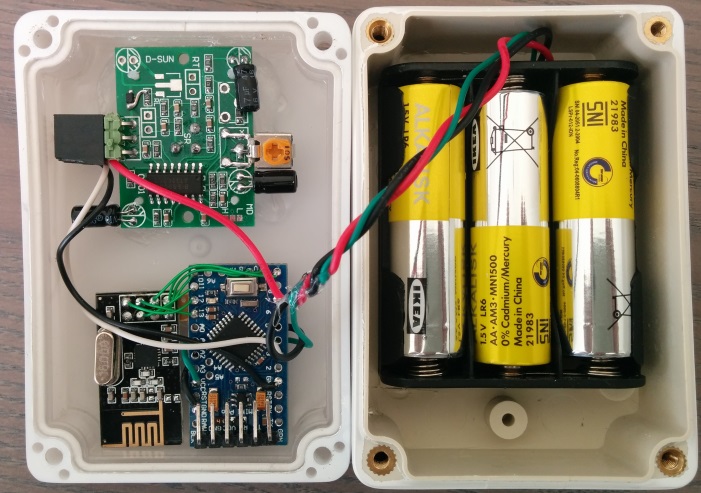
        (Btw. components on the HC-SR501 have been moved to the side to decrease the unit's depth)

        http://yveaux.blogspot.nl

        1 Reply Last reply
        0
        • YveauxY Offline
          YveauxY Offline
          Yveaux
          Mod
          wrote on last edited by
          #61

          FYI, I measured power comsumption on the Mogan when sleeping with and without regulator.
          The power consumption was significantly less with the voltage regulator, then when directly powered from 3xAAA (regulator removed).
          Therefore, my Molgan hack board design targets to use the PIR with regulator (3xAAA input) and the ATmega+nRF powered directly from 2xAAA.

          http://yveaux.blogspot.nl

          1 Reply Last reply
          1
          • T tomkxy

            @Yveaux Unfortunately, I still get false triggers. Do you also use a sensebender? Any ideas, what I can try. I tapped into as you suggested to the second battery.

            dynamiteD Offline
            dynamiteD Offline
            dynamite
            wrote on last edited by dynamite
            #62

            @tomkxy I Will put mine for a test run online tonight in the closet. If no trigger than it should be ok.
            Edit: did something wrong when removing led from pro mini so some debugging is required.... No testing tonight :cry:

            1 Reply Last reply
            0
            • T Offline
              T Offline
              tomkxy
              wrote on last edited by
              #63

              I googled a bit regarding PIR false alarms and found a couple of links. Apart from small bugs - which I have not in the room - air vents could trigger false alarms. Thus, I put back the plastic dome and now have sind 4 hours no false alarms. I am now convinced that my false alarms a most probably triggered by placement and may be air vents.

              http://de.actmeters.com/advice/five-causes-of-pir-false-alarms/
              https://www.youtube.com/watch?v=h0bp91xy5vY
              http://www.hkvstar.com/technology-news/how-to-install-pir-sensor-minimize-the-false-alarm.html

              YveauxY 1 Reply Last reply
              0
              • T tomkxy

                I googled a bit regarding PIR false alarms and found a couple of links. Apart from small bugs - which I have not in the room - air vents could trigger false alarms. Thus, I put back the plastic dome and now have sind 4 hours no false alarms. I am now convinced that my false alarms a most probably triggered by placement and may be air vents.

                http://de.actmeters.com/advice/five-causes-of-pir-false-alarms/
                https://www.youtube.com/watch?v=h0bp91xy5vY
                http://www.hkvstar.com/technology-news/how-to-install-pir-sensor-minimize-the-false-alarm.html

                YveauxY Offline
                YveauxY Offline
                Yveaux
                Mod
                wrote on last edited by
                #64

                @tomkxy of course you should always mount the fresnel cover. It focuses the incoming IR on the sensor and forms a barrier. Without the cover the sensor will always be more sensitive and have a much smaller field of view, increasing sensitivity even more.
                If an unmodified Molgan doesn't suffer from false triggers, a modified one also shouldn't.

                This is one more confirmation of the importance of describing your setup accurately :smirk:

                http://yveaux.blogspot.nl

                1 Reply Last reply
                0
                • T Offline
                  T Offline
                  tomkxy
                  wrote on last edited by
                  #65

                  I made a couple of additional modifications based on posts here and google results:

                  • put a short wait before the node goes to sleep -> based on reports from that forum
                  • read the motion pin twice with a small wait in between
                  • put a small alu foil between the radio and the PCB -> there are some reports in the internet that RF interference could cause false triggers

                  I had a close look at the sensor today and everything looked okay so far. However, I was moving into the room in and out. Let's see what the result tomorrow will be.

                  1 Reply Last reply
                  0
                  • T TimO

                    @tomkxy Nice write up! Do you have an idea on the accuracy of the humidity sensor within the case?

                    T Offline
                    T Offline
                    tomkxy
                    wrote on last edited by
                    #66

                    @TimO said:

                    @tomkxy Nice write up! Do you have an idea on the accuracy of the humidity sensor within the case?

                    I did some comparison measure regarding temp and humidity. I place an open Sensebender just beside the modded Molgan. The humidity measured at the Molgan was about 11% lower than the humidity measured by the open Sensebender. With respect to temp the Molgans temp was about 6% lower than the temp measured by the open Sensebender.

                    T 1 Reply Last reply
                    1
                    • T tomkxy

                      @TimO said:

                      @tomkxy Nice write up! Do you have an idea on the accuracy of the humidity sensor within the case?

                      I did some comparison measure regarding temp and humidity. I place an open Sensebender just beside the modded Molgan. The humidity measured at the Molgan was about 11% lower than the humidity measured by the open Sensebender. With respect to temp the Molgans temp was about 6% lower than the temp measured by the open Sensebender.

                      T Offline
                      T Offline
                      TimO
                      Hero Member
                      wrote on last edited by
                      #67

                      @tomkxy Thank you for reporting back!

                      1 Reply Last reply
                      0
                      • Cliff KarlssonC Offline
                        Cliff KarlssonC Offline
                        Cliff Karlsson
                        wrote on last edited by
                        #68

                        Ok, so if I as a complete beginner want to use a the original pir and control the lights all I need to do is:

                        Tap the power from the regulator U1 and power a 3.3v mini-pro (keeping the 3 batteries)

                        Remove Resistor R17 and connect the solderpoint nearest the chip to an arduino input and I can then basicly be able to run the standard motion sketch ? (After removing the photodiode and bridging the connectors?)

                        I can connect the the other solderpoint to an arduino output and if uploading a sketch witch puts that output HIGH the leds will turn on?

                        If I am fine with 30secs of triggertime I do not have to do anything more?

                        Are all my assumptions correct?

                        dynamiteD rollercontainerR 2 Replies Last reply
                        0
                        • Cliff KarlssonC Cliff Karlsson

                          Ok, so if I as a complete beginner want to use a the original pir and control the lights all I need to do is:

                          Tap the power from the regulator U1 and power a 3.3v mini-pro (keeping the 3 batteries)

                          Remove Resistor R17 and connect the solderpoint nearest the chip to an arduino input and I can then basicly be able to run the standard motion sketch ? (After removing the photodiode and bridging the connectors?)

                          I can connect the the other solderpoint to an arduino output and if uploading a sketch witch puts that output HIGH the leds will turn on?

                          If I am fine with 30secs of triggertime I do not have to do anything more?

                          Are all my assumptions correct?

                          dynamiteD Offline
                          dynamiteD Offline
                          dynamite
                          wrote on last edited by
                          #69

                          @Cliff-Karlsson correct!:smile:

                          1 Reply Last reply
                          0
                          • Cliff KarlssonC Cliff Karlsson

                            Ok, so if I as a complete beginner want to use a the original pir and control the lights all I need to do is:

                            Tap the power from the regulator U1 and power a 3.3v mini-pro (keeping the 3 batteries)

                            Remove Resistor R17 and connect the solderpoint nearest the chip to an arduino input and I can then basicly be able to run the standard motion sketch ? (After removing the photodiode and bridging the connectors?)

                            I can connect the the other solderpoint to an arduino output and if uploading a sketch witch puts that output HIGH the leds will turn on?

                            If I am fine with 30secs of triggertime I do not have to do anything more?

                            Are all my assumptions correct?

                            rollercontainerR Offline
                            rollercontainerR Offline
                            rollercontainer
                            wrote on last edited by
                            #70

                            @Cliff-Karlsson
                            Excellent summarized! Perfect HowTo!

                            Voted Cliff-Karlson for Documentation Team :-D

                            1 Reply Last reply
                            1
                            • Cliff KarlssonC Offline
                              Cliff KarlssonC Offline
                              Cliff Karlsson
                              wrote on last edited by
                              #71

                              Haha, right. Last question, if I also want the sensor to report battery-usage. Is there any way to accomplish that without soldering any more resistors?

                              YveauxY 1 Reply Last reply
                              0
                              • Cliff KarlssonC Cliff Karlsson

                                Haha, right. Last question, if I also want the sensor to report battery-usage. Is there any way to accomplish that without soldering any more resistors?

                                YveauxY Offline
                                YveauxY Offline
                                Yveaux
                                Mod
                                wrote on last edited by
                                #72

                                @Cliff-Karlsson Yes, there is!
                                Use my Vcc library!

                                http://yveaux.blogspot.nl

                                dynamiteD 1 Reply Last reply
                                1
                                • YveauxY Yveaux

                                  @Cliff-Karlsson Yes, there is!
                                  Use my Vcc library!

                                  dynamiteD Offline
                                  dynamiteD Offline
                                  dynamite
                                  wrote on last edited by
                                  #73

                                  @Yveaux @Cliff-Karlsson but in the scheme of cliff he is taken the power after the power regulator. So you are not
                                  Measuring the battery with your VCC library.

                                  YveauxY 1 Reply Last reply
                                  0
                                  • dynamiteD dynamite

                                    @Yveaux @Cliff-Karlsson but in the scheme of cliff he is taken the power after the power regulator. So you are not
                                    Measuring the battery with your VCC library.

                                    YveauxY Offline
                                    YveauxY Offline
                                    Yveaux
                                    Mod
                                    wrote on last edited by
                                    #74

                                    @dynamite You're right then. I didn't read his howto, just answered how to read battery voltage without voltage divider ;-)

                                    http://yveaux.blogspot.nl

                                    1 Reply Last reply
                                    0
                                    • Cliff KarlssonC Offline
                                      Cliff KarlssonC Offline
                                      Cliff Karlsson
                                      wrote on last edited by
                                      #75

                                      Ok, but if I measured right when talking the power from the regulator you could get 3v or ~4.5v witch i guess is directly from the batteries. If I connect the 4.5v to the power input on the same side as the tx/rx can I still not use the vcc library?

                                      dynamiteD 1 Reply Last reply
                                      0
                                      • Cliff KarlssonC Offline
                                        Cliff KarlssonC Offline
                                        Cliff Karlsson
                                        wrote on last edited by
                                        #76

                                        How would a sketch for this PIR look like? I tried combining the PIR and RelayActuator but my skills are not enough.

                                        This is what I have came up with:

                                        /**
                                         * The MySensors Arduino library handles the wireless radio link and protocol
                                         * between your home built sensors/actuators and HA controller of choice.
                                         * The sensors forms a self healing radio network with optional repeaters. Each
                                         * repeater and gateway builds a routing tables in EEPROM which keeps track of the
                                         * network topology allowing messages to be routed to nodes.
                                         *
                                         * Created by Henrik Ekblad <henrik.ekblad@mysensors.org>
                                         * Copyright (C) 2013-2015 Sensnology AB
                                         * Full contributor list: https://github.com/mysensors/Arduino/graphs/contributors
                                         *
                                         * Documentation: http://www.mysensors.org
                                         * Support Forum: http://forum.mysensors.org
                                         *
                                         * This program is free software; you can redistribute it and/or
                                         * modify it under the terms of the GNU General Public License
                                         * version 2 as published by the Free Software Foundation.
                                         *
                                         *******************************
                                         *
                                         * REVISION HISTORY
                                         * Version 1.0 - Henrik Ekblad
                                         * 
                                         * DESCRIPTION
                                         * Motion Sensor example using HC-SR501 
                                         * http://www.mysensors.org/build/motion
                                         *
                                         */
                                        
                                        // Enable debug prints
                                        #define MY_DEBUG
                                        
                                        // Enable and select radio type attached
                                        //#define MY_RADIO_NRF24
                                        #define MY_RADIO_RFM69
                                        
                                        #include <SPI.h>
                                        #include <MySensors.h>
                                        
                                        unsigned long SLEEP_TIME = 120000; // Sleep time between reports (in milliseconds)
                                        #define DIGITAL_INPUT_SENSOR 3   // The digital input you attached your motion sensor.  (Only 2 and 3 generates interrupt!)
                                        #define RELAY_1  9  // Arduino Digital I/O pin number for first relay (second on pin+1 etc)
                                        #define NUMBER_OF_RELAYS 1 // Total number of attached relays
                                        #define RELAY_ON 1  // GPIO value to write to turn on attached relay
                                        #define RELAY_OFF 0 // GPIO value to write to turn off attached relay
                                        
                                        
                                        #define CHILD_ID 1   // Id of the sensor child
                                        #define SECONDARY_CHILD_ID 4
                                        
                                        void before() { 
                                          for (int sensor=1, pin=RELAY_1; sensor<=NUMBER_OF_RELAYS;sensor++, pin++) {
                                            // Then set relay pins in output mode
                                            pinMode(pin, OUTPUT);   
                                            // Set relay to last known state (using eeprom storage) 
                                            digitalWrite(pin, loadState(sensor)?RELAY_ON:RELAY_OFF);
                                          }
                                        }
                                        
                                        // Initialize motion message
                                        MyMessage msg(CHILD_ID, V_TRIPPED);
                                        
                                        void setup()  
                                        {  
                                          pinMode(DIGITAL_INPUT_SENSOR, INPUT);      // sets the motion sensor digital pin as input
                                          
                                          
                                        }
                                        
                                        void presentation()  {
                                          // Send the sketch version information to the gateway and Controller
                                          sendSketchInfo("Light/Motion Sensor ikea", "1.0");
                                        
                                          // Register all sensors to gw (they will be created as child devices)
                                          present(CHILD_ID, S_MOTION);
                                          for (int sensor=1, pin=RELAY_1; sensor<=NUMBER_OF_RELAYS;sensor++, pin++) {
                                            // Register all sensors to gw (they will be created as child devices)
                                            present(sensor, S_LIGHT);
                                        }
                                        
                                        void loop()     
                                        {     
                                          // Read digital motion value
                                          boolean tripped = digitalRead(DIGITAL_INPUT_SENSOR) == HIGH; 
                                                
                                          Serial.println(tripped);
                                          send(msg.set(tripped?"1":"0"));  // Send tripped value to gw 
                                        
                                          // Sleep until interrupt comes in on motion sensor. Send update every two minute.
                                          sleep(digitalPinToInterrupt(DIGITAL_INPUT_SENSOR), CHANGE, SLEEP_TIME);
                                        }
                                        
                                        void receive(const MyMessage &message) {
                                          // We only expect one type of message from controller. But we better check anyway.
                                          if (message.type==V_LIGHT) {
                                             // Change relay state
                                             digitalWrite(message.sensor-1+RELAY_1, message.getBool()?RELAY_ON:RELAY_OFF);
                                             // Store state in eeprom
                                             saveState(message.sensor, message.getBool());
                                             // Write some debug info
                                             Serial.print("Incoming change for sensor:");
                                             Serial.print(message.sensor);
                                             Serial.print(", New status: ");
                                             Serial.println(message.getBool());
                                          }
                                          }
                                        

                                        But it does not complie after the last part is added. And I would also like to get the vcc -stuff into the same sketch. Could someone post a working sketch for this?

                                        dynamiteD 1 Reply Last reply
                                        0
                                        • Cliff KarlssonC Cliff Karlsson

                                          Ok, but if I measured right when talking the power from the regulator you could get 3v or ~4.5v witch i guess is directly from the batteries. If I connect the 4.5v to the power input on the same side as the tx/rx can I still not use the vcc library?

                                          dynamiteD Offline
                                          dynamiteD Offline
                                          dynamite
                                          wrote on last edited by
                                          #77

                                          @Cliff-Karlsson you can only use the VCC sketch if you by pass the voltage regulators. So power the arduino from two batteries by a separate wire.

                                          1 Reply Last reply
                                          0
                                          Reply
                                          • Reply as topic
                                          Log in to reply
                                          • Oldest to Newest
                                          • Newest to Oldest
                                          • Most Votes


                                          24

                                          Online

                                          11.7k

                                          Users

                                          11.2k

                                          Topics

                                          113.0k

                                          Posts


                                          Copyright 2019 TBD   |   Forum Guidelines   |   Privacy Policy   |   Terms of Service
                                          • Login

                                          • Don't have an account? Register

                                          • Login or register to search.
                                          • First post
                                            Last post
                                          0
                                          • MySensors
                                          • OpenHardware.io
                                          • Categories
                                          • Recent
                                          • Tags
                                          • Popular